Week 6 - CHT Analysis on a Graphics card
WEEK 7: Conjugate Heat Transfer analysis for a Graphics card
Introduction:
The Conjugate Heat Transfer (CHT) analysis allows us to study the heat transfer occurring between solid and fluid. It involves the variations of temperature within solids and fluids, due to thermal interaction between the solids and fluids. As evident, conduction often dominates in solids and convection usually dominates in case of fluids. Efficiently combining the heat transfer in fluids and solids helps in effective designing of heaters, coolers, or heat exchangers. The applications of these type of simulation can be extended further to study heat transfer occurring in heat exchangers, cooling of electronic equipment, general-purpose cooling and heating systems and much more.
A graphics card is a type of display adapter or video card installed within most computing devices to display graphical data with high clarity, colour, definition and overall appearance. It is a hardware which is used to increase the video memory of a computer, and make its display quality more high definition. It also makes the computer more powerful and gives it the capacity to do higher – level works efficiently.
A graphic card basically consists of following components explained in detail below:
<!-- [if !supportLists]-->GPU (Graphics Processing Unit) or Processor:
The GPU is the heart of the graphics card and is responsible for processing and rendering visual data. It performs complex mathematical calculations required for 2D and 3D rendering, image processing, and handling various graphical effects in video games and other applications.
<!-- [if !supportLists]-->VRAM (Video Random Access Memory):
VRAM is dedicated memory used by the GPU to store graphical data and textures. It acts as a high-speed buffer between the GPU and the display, allowing the GPU to quickly access and manipulate visual information.
<!-- [if !supportLists]-->PCB (Printed Circuit Board):
The PCB serves as the main platform to which all the components are connected. It provides electrical connections between the GPU, VRAM, power connectors, and other components.
<!-- [if !supportLists]-->Cooling solutions:
Graphics cards generate a significant amount of heat during operation. To keep the GPU and other components at safe temperatures, a cooling solution is employed, which typically consists of a combination of fans, heatsinks, and sometimes liquid cooling systems.
<!-- [if !supportLists]-->Power connectors:
Graphics cards require additional power beyond what can be supplied through the motherboard's PCIe slot. Depending on the card's power requirements, one or more power connectors, are included to provide the necessary power from the power supply unit.
<!-- [if !supportLists]-->Display Outputs:
Graphics cards have various display outputs to connect to monitors and other display devices. Common display outputs include HDMI, DisplayPort, DVI, and sometimes VGA
<!-- [if !supportLists]-->Voltage Regulation Modules (VRMs):
VRMs regulate the voltage supplied to the GPU and other components on the graphics card. They ensure stable and reliable power delivery to support the GPU's varying power demands during operation.
<!-- [if !supportLists]-->Capacitors and Resistors:
These components support the power delivery and filtering circuits on the graphics card. Apart from these components some graphics card also have Video encoding/decoding hardware (for high – definition video support and editing), backplates (on reverse side of PCB’s serving as a structural support and also dissipate some amount of heat from backside of the card) and some high – end cards also have RGB LED’s and other aesthetics features.
The model used in the simulation is a basic representation of the graphic card and hence the focus will be on only some of the major components rather than all listed above, such as graphical processing unit or the processor, cooling systems or fins and the motherboard/PCB. To make the simulation more realistic as possible, the actual materials used in the components, their functions and their properties required for simulations are explained below.
<!-- [if !supportLists]-->Motherboard (PCB):
This is commonly made of combinations of materials to ensure proper structural integrity and electrical connections. The basic structural material is Fibreglass (FR4) which provides the mechanical strength and stability to board also acting as an insulator between conductive copper traces. Copper is also used in traces which are etched on the surface of the fibreglass to create conductive pathways on the PCB between other components. A protective layer called as Solder mask is applied on the copper traces to protect from short circuits and provide insulation.
<!-- [if !supportLists]--><!--[endif]-->Cooling systems:
The cooling systems are also referred to as the cooling fins or the heat sinks which are responsible for dissipating the heat that is generated by the GPU or the processor during its functioning and dissipates it into the surrounding air. Aluminium is the most commonly used material due to its excellent thermal conductivity and relatively low cost. High – end graphic cards which are known for top – tier cooling performances also use Copper.
<!-- [if !supportLists]-->Processor (GPU):
The GPU is designed specifically for handling graphical computations and rendering tasks, making it highly efficient at processing and transforming large amounts of graphical data and just like most other modern electronic components, including CPUs (Central Processing Units), Silicon is the semiconductor material of choice for manufacturing processors due to its unique properties that make it suitable for handling electrical signals and performing complex computations.
<!-- [if !supportLists]-->
Objective:
- <!-- [if !supportLists]-->To perform CHT analysis for graphics card with velocities 1 m/s, 3m/s and 5 m/s.
- <!-- [if !supportLists]-->To evaluate the maximum heat transfer coefficient and the temperature attained by the processor.
- <!--[endif]-->To identify the potential hotspot region of the graphics card.
GEOMETRY
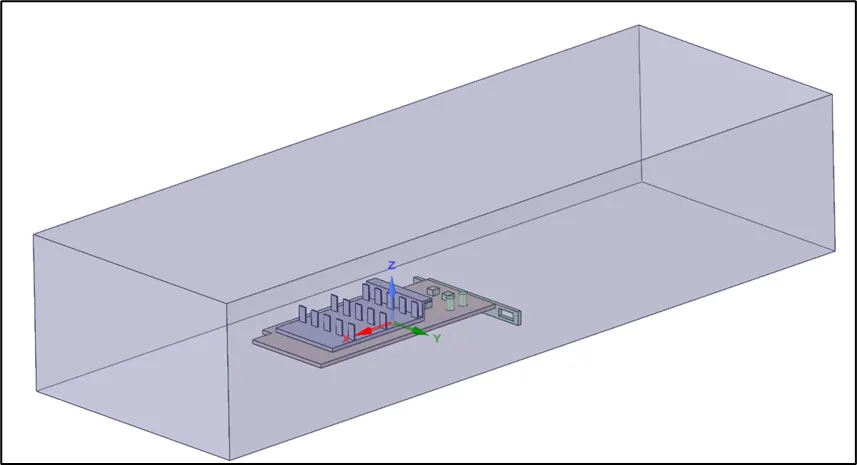
Import the made – up geometry of the graphics card. The enclosure of dimensions 191*65*40.5 mm is prepared around the graphic card for the simulation.
MESHING
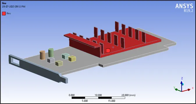
Named selections
\
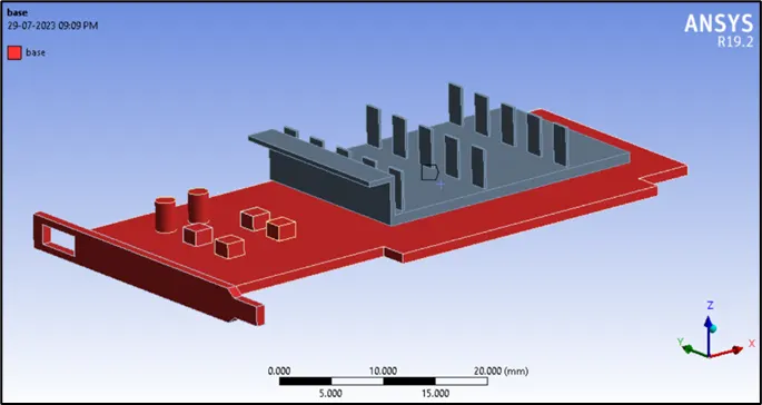
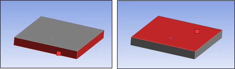
The named selection for processor and processor sides are done separate in order to make it easier to identify and monitor the surface heat transfer coefficient of the processor, as all the 4 sides will be participating in the convective heat transfer.
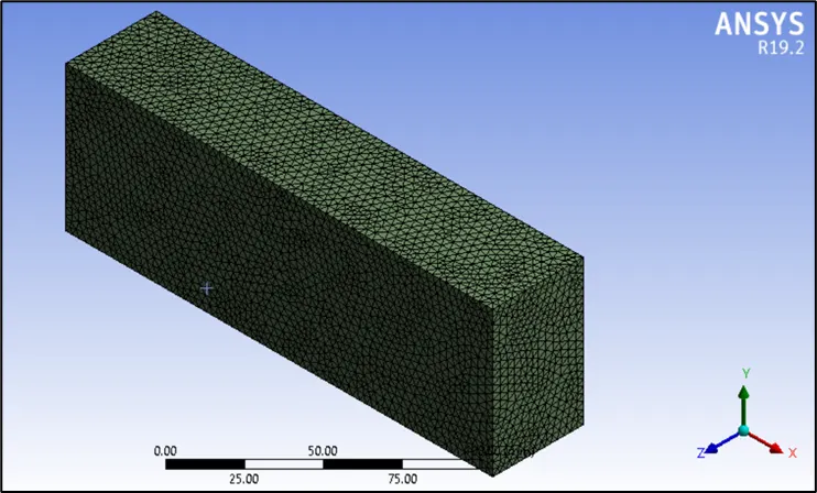
MESH
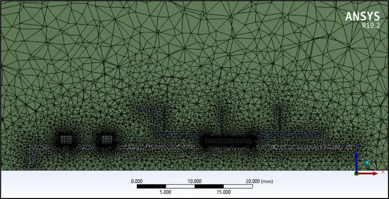
- Face sizing is provided on the enclosure with an element size of 3 mm.
- Body sizing is provided on the base, fins and processor of the graphic card with an element size of 0.5 mm.
- Edge sizing is provided on the edges of the processor and the memory units with an element size of 0.1 mm to obtain accurate results.
- It consists of 1279300 elements with an average element quality, aspect ratio, skewness and orthogonal quality of 0.83, 1.88, 0.24 and 0.75 respectively.
SIMULATION SETUP
- Solver type: Pressure based steady state solver
- Turbulence model: K – omega SST model with energy equation enabled.
Table 1: Properties of the materials used in the study
|
Components |
Material |
Density (kg/m3) |
Specific heat (J/kg-K) |
Thermal conductivity (W/m-K) |
|
Base (PCB) |
FR – 4 |
1850 |
1500 |
0.3 |
|
Fins |
Aluminium |
2719 |
871 |
202.4 |
|
Processor |
Silicon |
2330 |
705 |
148 |
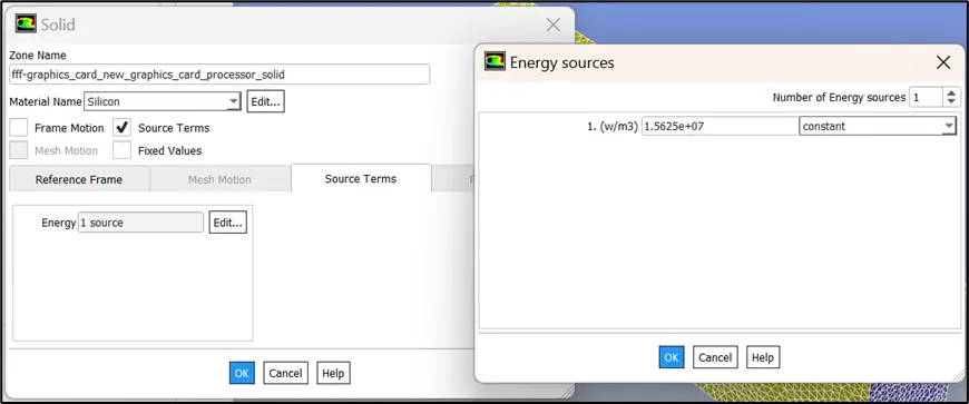
Further, we must provide a power source to estimate the temperatures that will be obtained through simulation, which is calculated as follows:
- Heat dissipated = 1 W
- Volume of the processor = 8*8*1 mm = 64 mm3
- Heat generated per unit volume = 1 / (64 * 10-9) = 15,625,000 W/m3
The materials Silicon and FR – 4 are not available directly in the fluent database, hence any solid material is copied and the properties are edited.
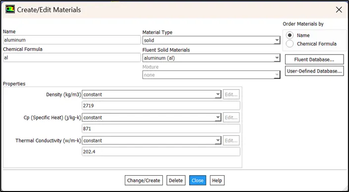
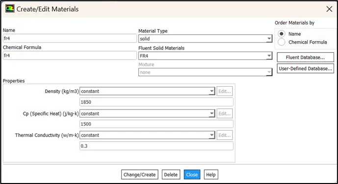
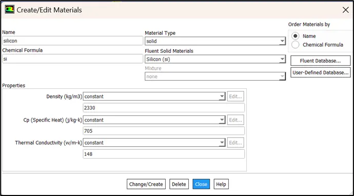
Assigning the required cell zone with correct cell zone conditions, material and zone type.
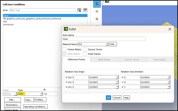
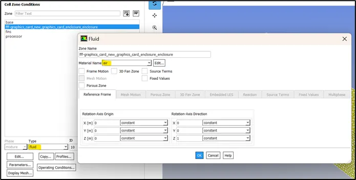
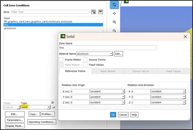
The processor is responsible for generating the heat energy hence an energy source is provided.
Boundary conditions:
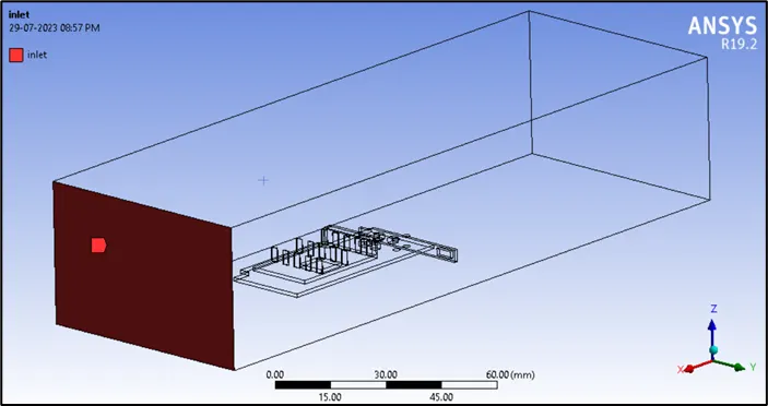
- Inlet: Type: velocity = 1 m/s
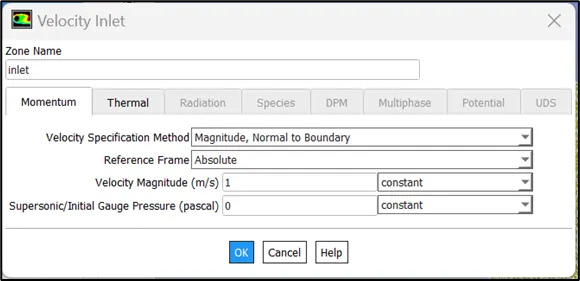
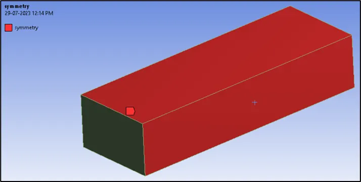
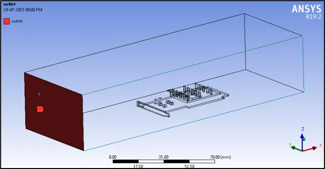
- The outlet and symmetry boundary conditions are set default to pressure and symmetry type respectively.
- The reference values are computed from inlet and the area is 32*10-4 m2 (4*(0.008*0.001)), i.e., the areas for convection.
- The length for the reference values is 0.008 m.
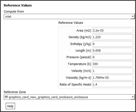
- Define a Max. report of volume type to monitor the maximum temperature and a surface report to monitor the surface heat transfer coefficient of the processor.
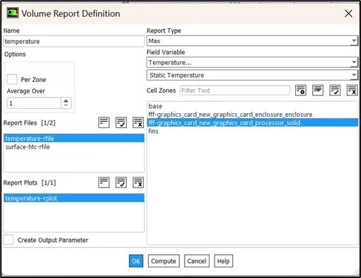
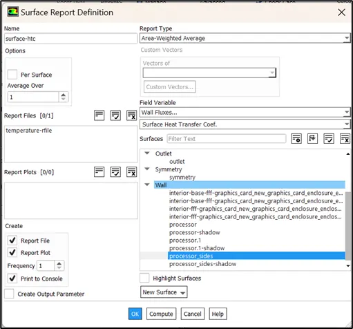
- Initialize using hybrid initialization and run the simulation for 500 iterations.
CASE 1: Inlet velocity = 1 m/s
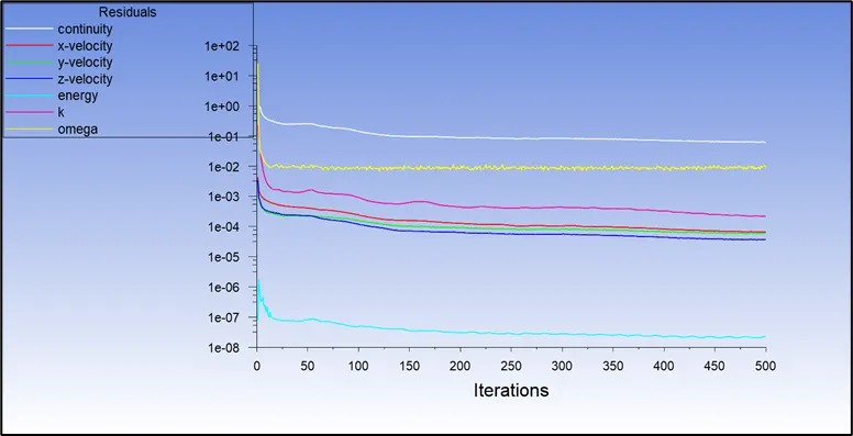
Residual plot
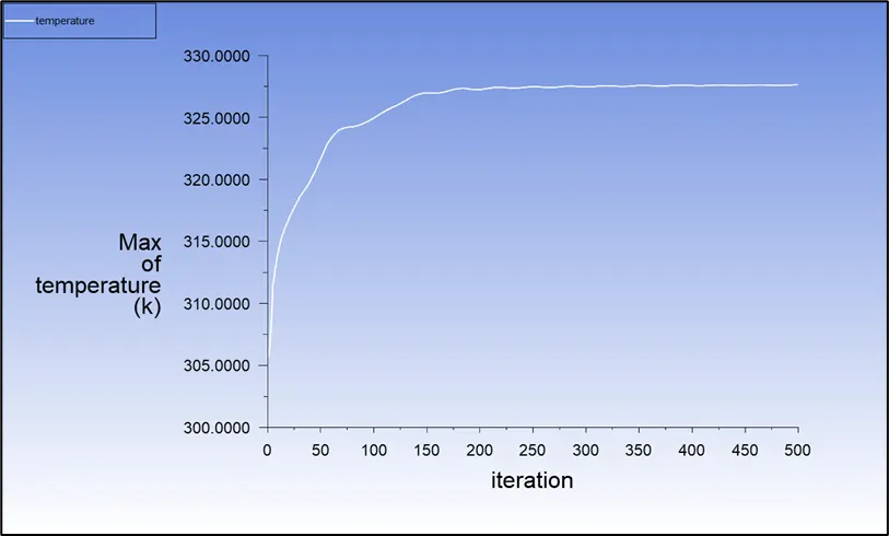
Maximum temperature plot
Average surface heat transfer coefficient plot
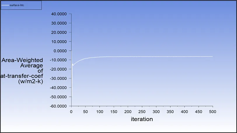
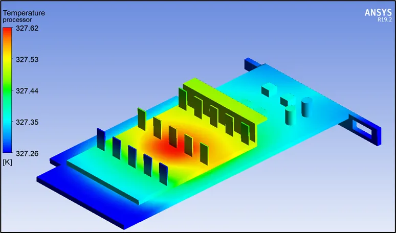
- The max temperature at the processor is 327.6 ℃ and the surface heat transfer coefficient at the processor is -6.39 W/m2.K, where negative sign indicates that the heat is transferred out of the system i.e., the processor.
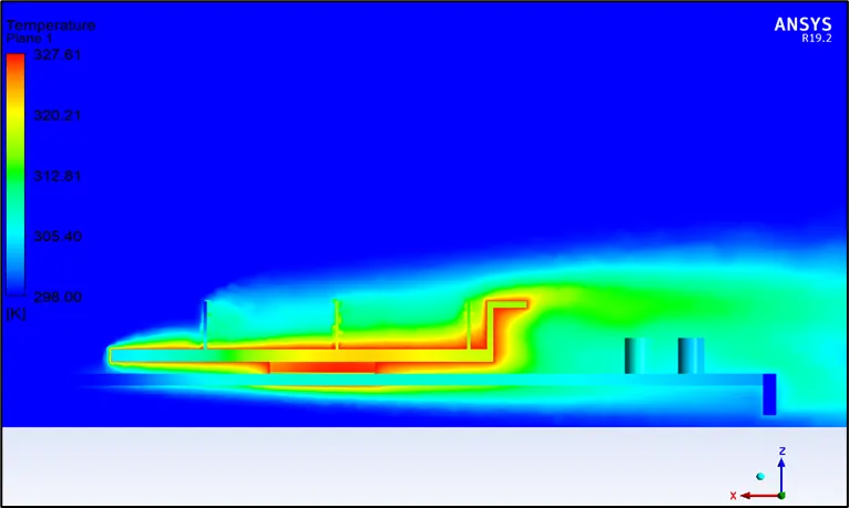
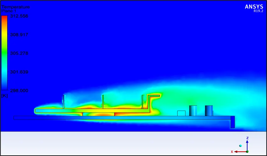
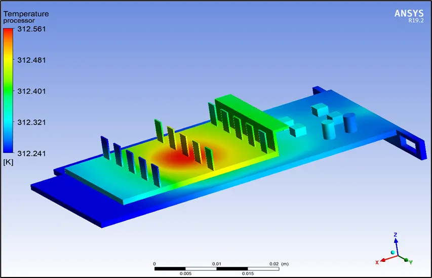
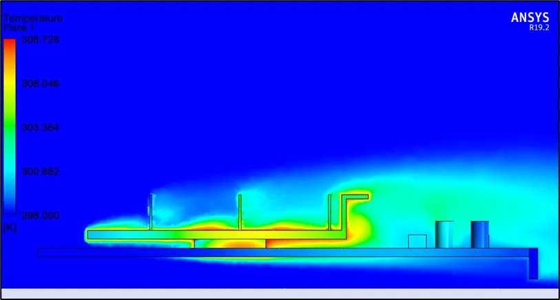
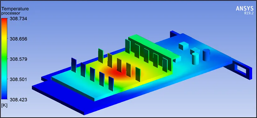
- Since the processor gets heated up during its operation, it dissipates heat to the fins on the PCB (in the form of conduction) and simultaneously dissipates heat to the ambient through convection. The portion of the fins directly in contact of the processor through PCB will receive maximum heat and is termed “hotspot” as evident from the postprocessing.
Temperature contour
Case 2: Inlet velocity = 3 m/s
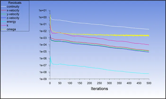
Residual plot
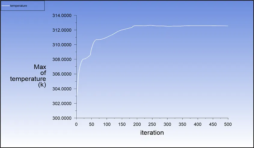
Maximum temperature plot
Max. Temperature = 312.56 ℃
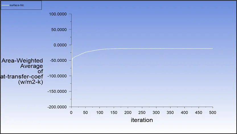
Average surface heat transfer coefficient plot
Avg. surface heat transfer coefficient = -11.17 W/m2-K
Temperature contour
Case 2: Inlet velocity = 5 m/s
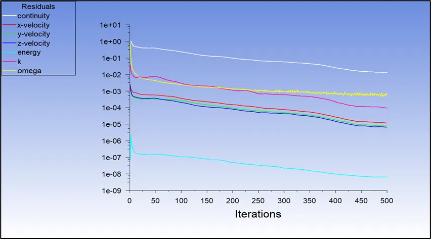
Residual plot
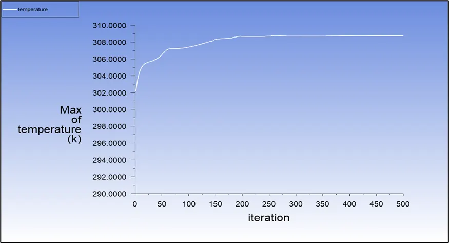
Maximum temperature plot
Max. Temperature = 308.74 ℃
Average surface heat transfer coefficient plot
Avg. surface heat transfer coefficient = -17.747 W/m2-K

Temperature contour
CONCLUSIONS
|
Sl. No: |
Velocity (m/s) |
Surface heat transfer coefficient (W/m2-K) |
Max. temperature of processor (℃) |
|
1. |
1 |
-6.39 |
327.6 |
|
2. |
3 |
-11.17 |
312.56 |
|
3. |
5 |
-17.747 |
308.74 |
The study shows that the processor is the potential hotspot of the graphic card assembly and is the sole source of heat generation. Further, the heat generated by processor is dependent on its workload, higher workload leads to higher heat generated. The above results show that, as there is an increase in the velocity of air the decrease in the temperature of the processor can be observed. This is because, as the velocity increases the heat that is carried away by the air also increases, which in turn increases the heat transfer coefficient of the processor.