Week 3 Challenge : CFD meshing on Turbocharger
https://drive.google.com/file/d/1aIbRNSbiC0WMZFB82vxHP0rMMCEmtCOW/view?usp=share_link
AIM:
To perform the geometrical cleanup and assign surface meshing and volumetric meshing for the turbocharger model.
PROCEDURE:
The turbocharger model is imported into ANSA interface and it can be observed, there are locations where overlapping components are present (glitches) which must be deleted.
- The overlapped surfaces can be confirmed using ‘topo’ option under ‘faces’ menu by the presence of triple cons.
- It can be seen that the overlapping surface (pink) has the same colour of cross hatch which can be used to delete the overlapped surface easily.
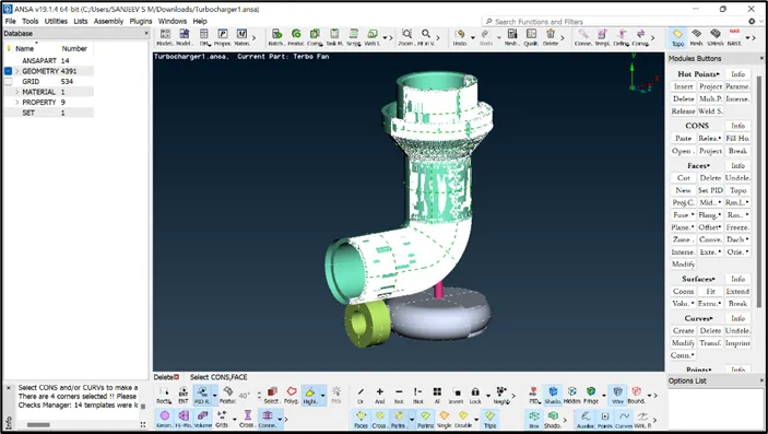
- After the deletion of overlapped surfaces, the extra layer of geometry can be deleted by selecting that surface with entity mode enabled.
- At the same location, using ‘coons’ option with loop enabled the geometry can be created to form a closed component.
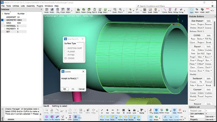
- The upper part of the cylinder consisting of single cons cannot be directly converted into a closed surface, hence we use multi-project feature and select the hot-points and project it on the top con.
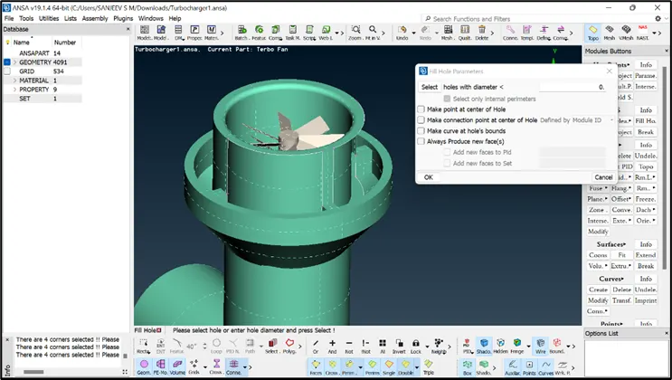
- Now by using the top con as a reference, the surface can be created in steps using ‘coons’ feature with entity mode enabled. This creates rectangles which can be used as reference to create a closed surface further using ‘fill hole’ feature.
- Next, we can see there is an intersection of conical surface with the cylindrical surface which is to be rectified. To ensure this the unwanted surfaces are hidden using the ‘not’ feature.
- Using ‘intersect’ option in ‘faces’ menu, select conical surface as first surface (pink coloured) then middle click and select the cylinder as second surface (blue colour) and again middle click.
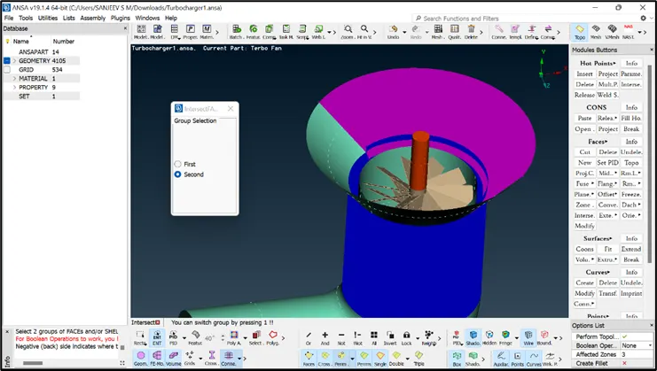
- This intersects the two surfaces but there is formation of triple con (extra surfaces) which are deleted using universal delete option.
- The shaft attached to the propeller also has glitching which is removed using universal delete option. Still the shaft end shows the presence of triple cons which can be converted into 3 single cons using ‘release’ option. The unnecessary hot-points are also deleted using the delete option.
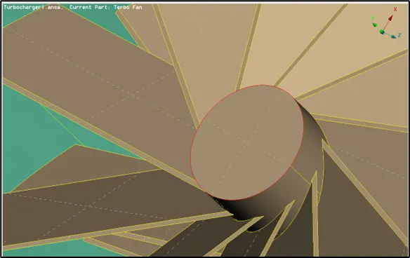
- Next step is to create a surface for the base of the turbocharger. Here, the regular approach of creation of new surfaces is not possible as the surface to be created is a curved one rather than a regular shape.
- Create hot-points using parameter option with the distance of 0.5 mm, so that they are equally placed 0.5 mm apart from each other. Repeat the same process on the other side of the curve. The sole reason to create the hot-points is to ensure a smooth surface with no intersection with other surfaces.
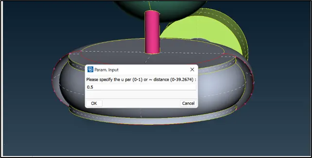
- Now using ‘new face’ feature and ‘coons’ option with entity mode enabled, create a surface such that the outer surface is not touching the inner surface of the turbocharger bottom part. Repeat the same process on the bottom side of the base.
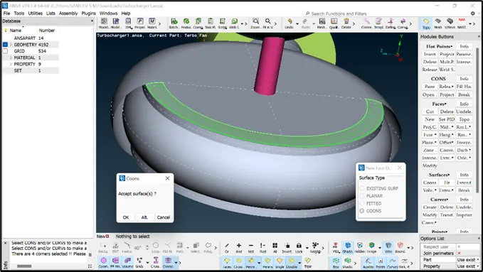
- Repeat the above step till the geometry is closed as shown in figure.
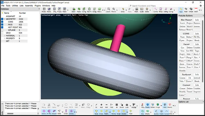
- Perform geometry check to ensure presence of single cons and triple cons and eliminate them. The shaft part of the model contains a single con, hence by performing topo to that location we convert it to a triple con.
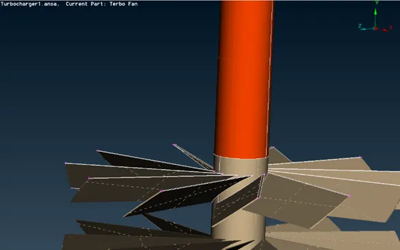
- The geometry check again shows that there are no single cons but many triple cons which are warnings and also might be some overlapped surfaces which must be checked and eliminated as per the requirement.
- At the upper part of the shaft, we can see triple bonds which show that a single volume is divided into three volumes, which is not ideal, hence we can use universal delete option and delete the surfaces. The same process is followed throughout the length of the shaft.
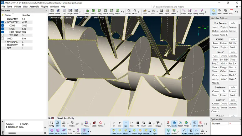
- Along the length of the shaft, there is still a triple con which confirms the presence of overlapped surfaces. To rectify this, use project option in ‘cons’ menu. Select the cons on the shaft which is to be cut and select the cross hatch of the shaft and middle click.
- This projection is not uniform and hence use ‘fine’ option in ‘auxiliaries’ menu and multiple clicks on the cons to make them uniform.
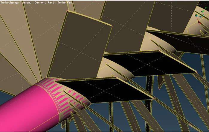
- This makes the shaft containing one single con and a double con. Use release and right click to make them single cons and later select topo option on the same location which gives a triple con indicating a overlapped surface. This surface is deleted using universal delete option.
- Open the PID manager, select individual PIDs and rename them accordingly. Also, check for any locations where the geometry is open. Use ‘new’ option and close the surfaces for proper volumetric meshing.
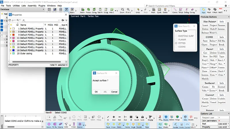
- All the components are assigned with the PID names as required. The extra PIDs which are irrelevant are forcefully deleted using ‘compress’ feature. All the assigned PIDs and the compress feature is as shown in figure below.
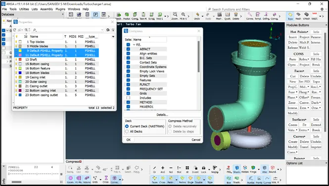
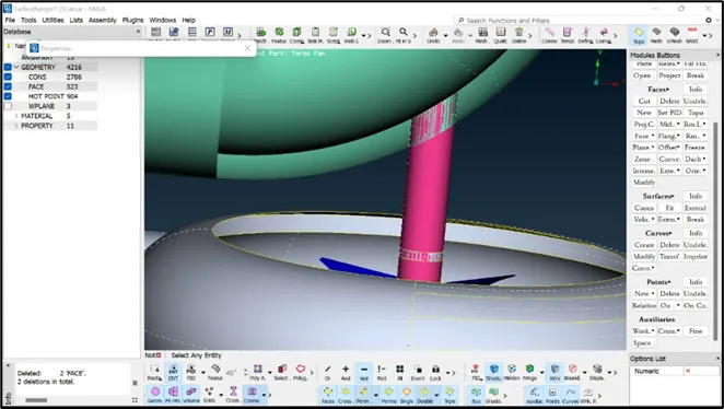
- The region of the shaft with blades stage_1 consisting of triple cons indicates overlapping of surfaces. The overlapping surfaces are deleted so as to obtain the shaft as a single component throughout its length.
- Some locations of the compressor casing and the turbo casing consists of overlapping surfaces (as shown in image) is deleted using universal delete option.
SURFACE MESHING:
- Under PID manager, select compressor casing, casing inlet and outlet and select view only by right click.
- Assign the target length of 5 mm to both perimeters and macros of the geometry by using length option in perimeters menu.
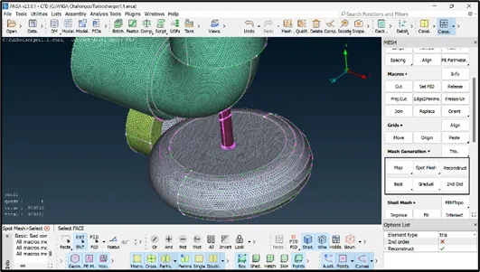
- Use spot mesh under mesh generation menu, select the components to be meshed and right click to assign the mesh. The assigned mesh is uniform and consists of 118514 tria elements.
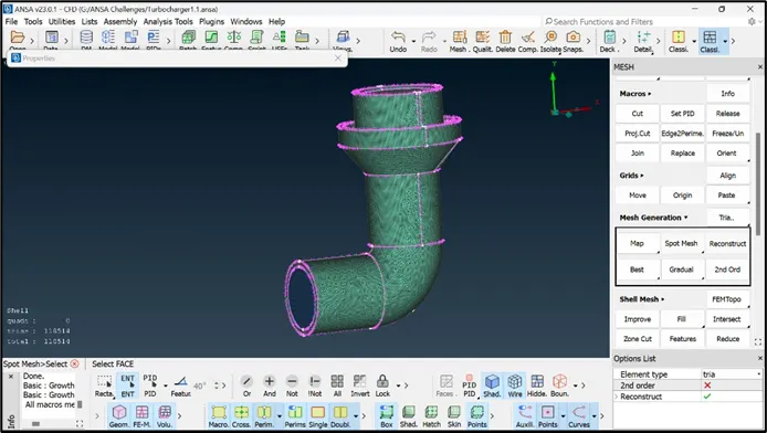
- Select turbo casing and inlet casing cover from PID manager under visible only option. Assign the target length of 5 mm to both perimeters and macros of the geometry by using length option in perimeters menu.
- Use spot mesh under mesh generation menu, select the components to be meshed and right click to assign the mesh. The assigned mesh is uniform and consists of 49924 tria elements.
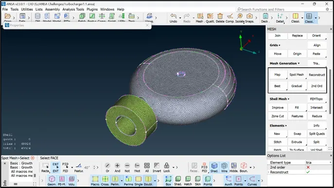
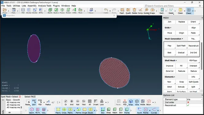
- Similarly select bottom casing inlet and outlet from PID manager under visible only option. Assign the target length of 5 mm to both perimeters and macros of the geometry by using length option in perimeters menu. Use spot mesh under mesh generation menu, select the components to be meshed and right click to assign the mesh. The assigned mesh is uniform and consists of 1048 tria elements.
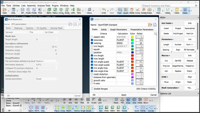
- Next the surface mesh of impeller is done. The outer parts of the turbocharger are hidden and the target length, minimum and maximum target length are defined as 2 mm, 1 mm and 3 mm respectively under quality criteria and mesh parameters.
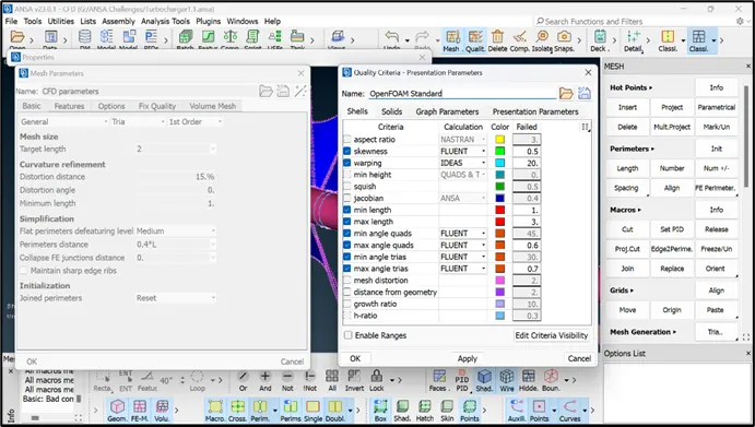
- Assign the target length of 2 mm to both perimeters and macros of the geometry by using length option in perimeters menu. Use select option in spot mesh under mesh generation menu by long press, select the components to be meshed under PID mode and right click to assign the mesh. The assigned mesh is uniform and consists of 20701 tria elements.
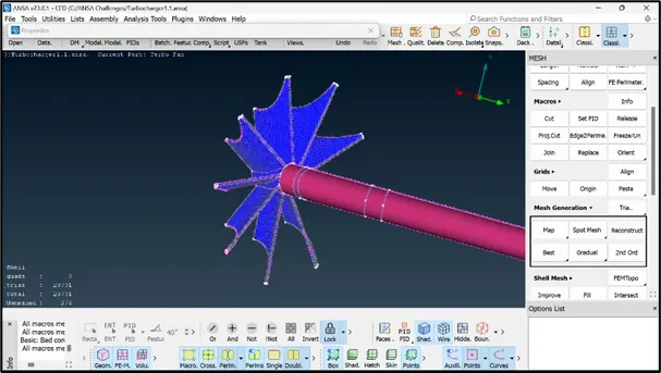
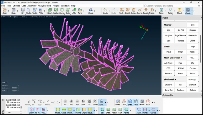
- Next the surface mesh of the blades is performed. The mesh parameters and the quality criteria are given with the target length of 1 mm and minimum and maximum length of 0.5 mm and 2 mm respectively. The target length of 1 mm is then assigned to all the perimeters and the macros using length feature under perimeters menu.
- The mesh is assigned using select option in spot mesh by enabling the PID mode. The mesh of blades consists of 666085 elements of tria type.
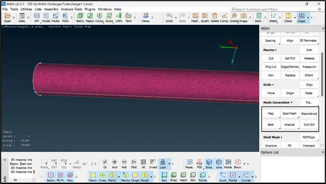
- The similar steps as that of surface meshing of blades is followed for that of rotor shaft. The meshed component contains 79585 tria elements.
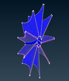
- It can be seen that some locations of the impeller, the mesh has been erased. Hence, repeat the process by assigning the quality criteria and mesh parameters with 2mm and minimum and maximum target lengths of 1 mm and 3 mm respectively.
- Similar problem arises with rotor shaft since the meshing parameters are changing at the intersection of rotor shaft and the impeller. To overcome this, the rotor shaft region is meshed with mesh length of 1 mm and minimum and maximum length of 0.5 mm and 2 mm. The mesh length of 1 mm is used at the perimeters only and the spot mesh with select option is used to assign the surface mesh.
- It can be seen that the rotor shaft has a uniform mesh of 1 mm but as meshing approaches towards the impeller it has a transition phase and it has increased between 1 mm to 2 mm and further the impeller has a meshing of 2 mm.
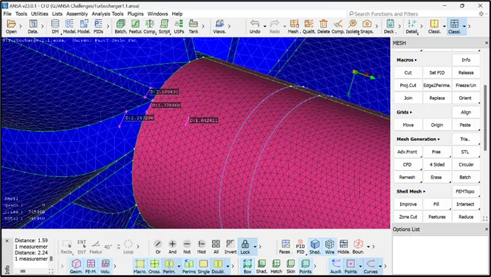
- Similarly, the meshing at the area of contact of rotor shaft with the turbo casing and compressor casing is erased. To overcome this, assign the quality criteria and the mesh parameters with target length, minimum and maximum target length of 5 mm, 3 mm and 7 mm. The target length of the perimeters is assigned as 5 mm and the macros are set between 1 mm to 5 mm. The mesh is assigned using spot mesh with select option at the outer and inner part of turbo casing and compressor casing.
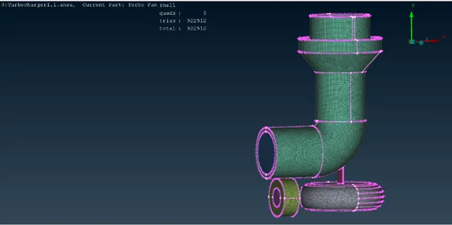
- The total elements in the surface mesh consists of 922512 tria elements.
VOLUMETRIC MESH:
- Volumetric mesh is also known as solid meshes which consists of solid mesh elements. The important criteria for the volumetric mesh are that the surface mesh must be performed prior to it. The volumetric mesh is performed to the space or voids present inside a particular volume.
- Click on define option under volumes menu and select detect on whole database (whole bd) and click ok. The dialog box shows the total number of volumes detected by ANSA, which can be volume meshed or deleted as per requirement.
- The volumes highlighted in the image are those where the volumetric meshing is to be deployed and the remaining ones need to be deleted as they are the thickness of the parent geometry.
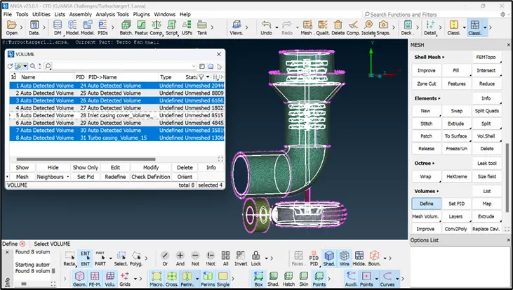
- The thickness components of the geometry are deleted and the required volumes are used for meshing using show only option.
- The volumetric meshing is assigned using ‘Tetra mesh CFD’ under ‘Mesh Volume’ feature under ‘Volumes’ menu. The ‘Tetra’ represents the element type and ‘CFD’ represents the application.
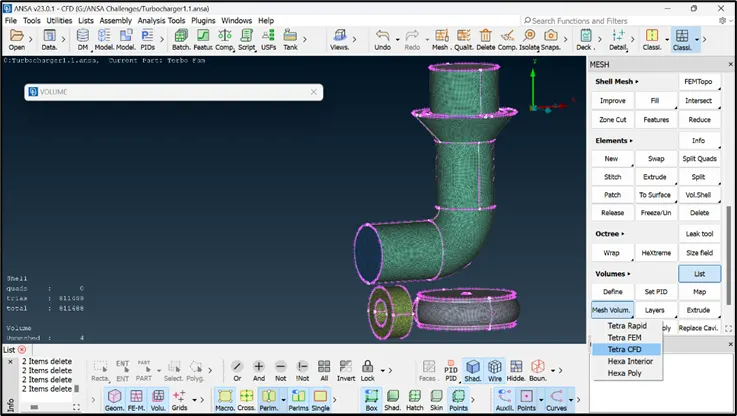
- Select ‘volume’ option and select the volume to be meshed, then middle click. Again select ‘solid’ option and select the same volume and middle click to assign the mesh.
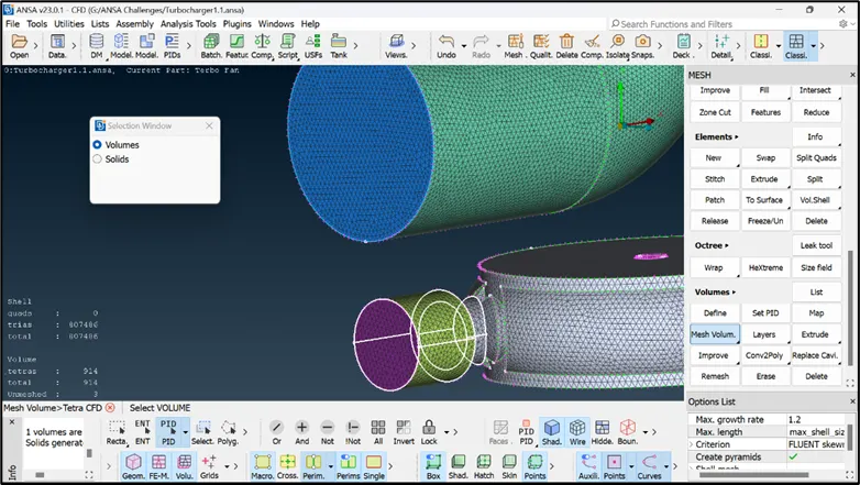
- The same steps are repeated to complete the volumetric mesh of the volumes detected by ANSA. The total number of elements (6981442) will be higher than the surface mesh elements and the elements will be tetrahedron shape.
- The volumes that are meshed can be viewed in ‘TOPO’ mode by disabling the ‘Geometry’ and ‘FE-Mode’ at the bottom of the interface.
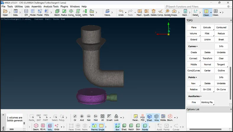
- The tetra elements can be viewed by using ‘NOT’ option in ‘entity’ mode.
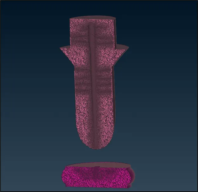
- The cross section of the volumetric mesh in the top view shows the volumetric mesh deployed throughout the volume.
- It can be observed that the areas near the shaft, blades, impeller intersecting the turbo casing volume has smaller tetra elements than that of the turbo casing volume alone.
- This is due to the target length assigned during the surface meshing, i.e., 1 mm at the blades and 5 mm at the turbo casing.
RESULTS AND CONCLUSION:
- The challenge comprises of geometrical clean-up, surface meshing and volumetric meshing of the given turbocharger model.
- It can be observed that the surface meshing is an important and basic criterion for the volumetric meshing.
- The volumetric meshing elements are more in number than that of surface meshing elements as they are 3 dimensional in nature.
- The locations of intersection of 2 PIDs show a variation in volumetric mesh throughout, which is mainly due to the different target lengths provided during the surface meshing.
- Further, the target lengths during surface meshing also influence the size of the tetra element during volumetric meshing.