Project 1 : CFD Meshing for Tesla Cyber Truck
AIM:
To perform geometrical clean – up and meshing of the model with appropriate target lengths.
TOPO CLEAN – UP:
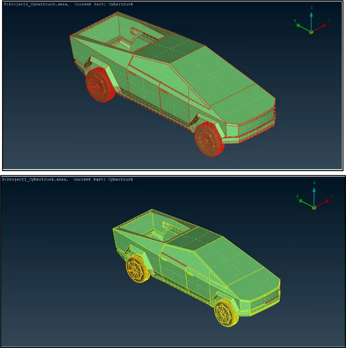
- The model imported to the interface has single cons, hence we use ‘topo’ option to reduce them.
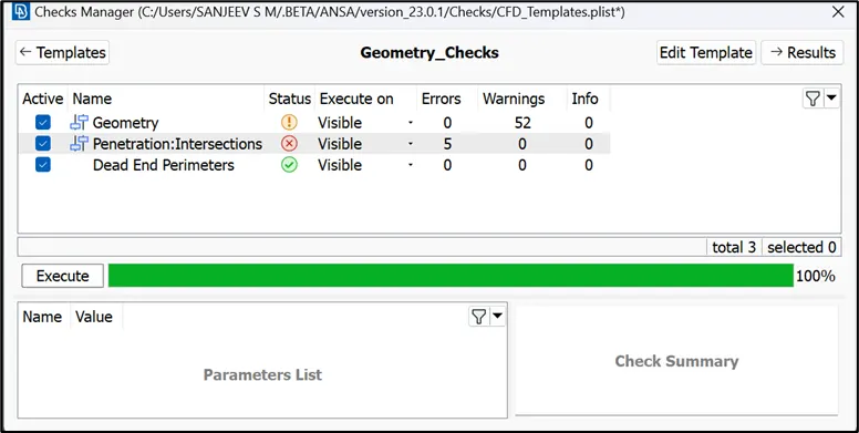
- To find out the presence of geometrical errors and penetration errors in the model, the geometry and penetration checks are performed using ‘checks manager’.
- The open surfaces are closed using ‘coons’ option to remove all the single cons. The geometry check is again performed to confirm the elimination of single cons.
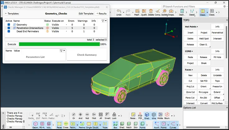
- The checks manager still indicates the presence of intersections and dead-end parameters which needs to be eliminated since they can cause errors during meshing.
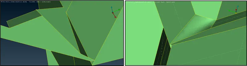
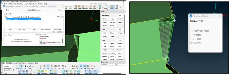
- As shown below, there are small surfaces with sharp corners and intersections which can be eliminated by deleting the surfaces (left) and creating new ones (right).
- The geometry check has again revealed the presence of a dead-end parameter which is resolved by deleting the surface and creating a new one.
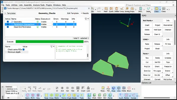
- Now the geometry only has 4 intersections between the wheel guard and the wheel shaft.
- Isolate the intersections one by one, and delete the overlapped surface (brown crosshatch).
- Use ‘delete’ option in hot points and delete the excess hot-points.
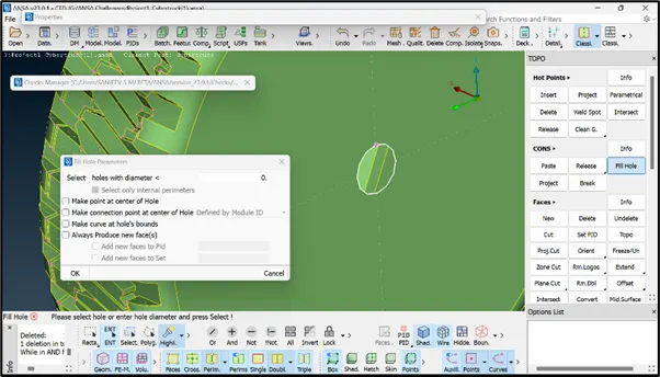
- Use fill hole option to create a surface on the tyre.
- Repeat these steps for all the remaining similar type of intersections.
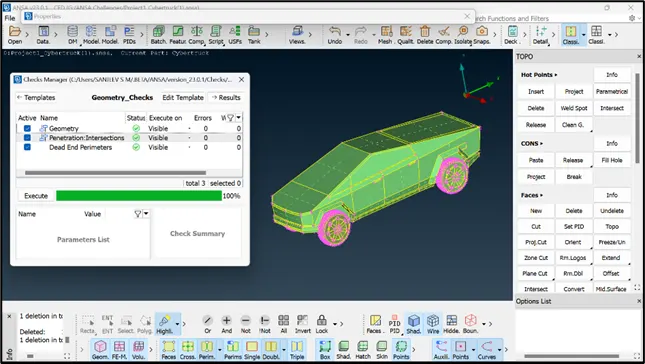
- The geometry is now free from all types of errors and can be proceeded with PID assigning and surface meshing.
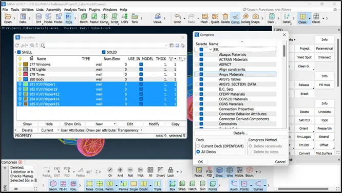
- Create 4 PIDs in PID manager with the names body, tyres, lights and windows. Assign the respective PIDs and delete the extra PIDs using compress option.
SURFACE MESHING:
1. LIGHTS:
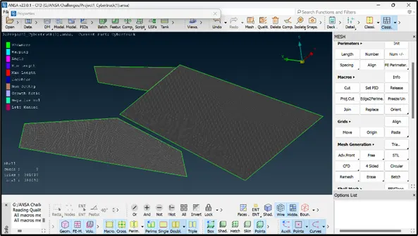
- Switch to ‘ENT’ mode, turn on ‘hidden’ feature and isolate the ‘Lights’ PID.
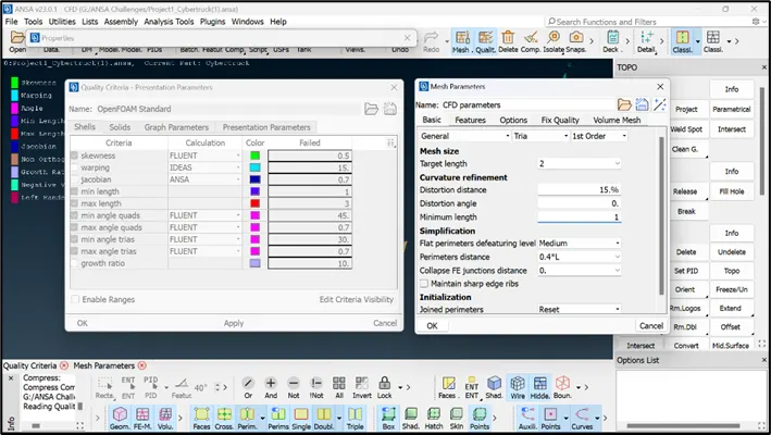
- The target length for meshing is assumed as 2 mm and the quality criteria for maximum and minimum mesh length is set as 1 mm and 3 mm.
- Using ‘length’ option, select the perimeters and macros of the PID and enter the mesh length assumed.
- Use ‘spot mesh’ ‘visible’ option to apply the mesh.
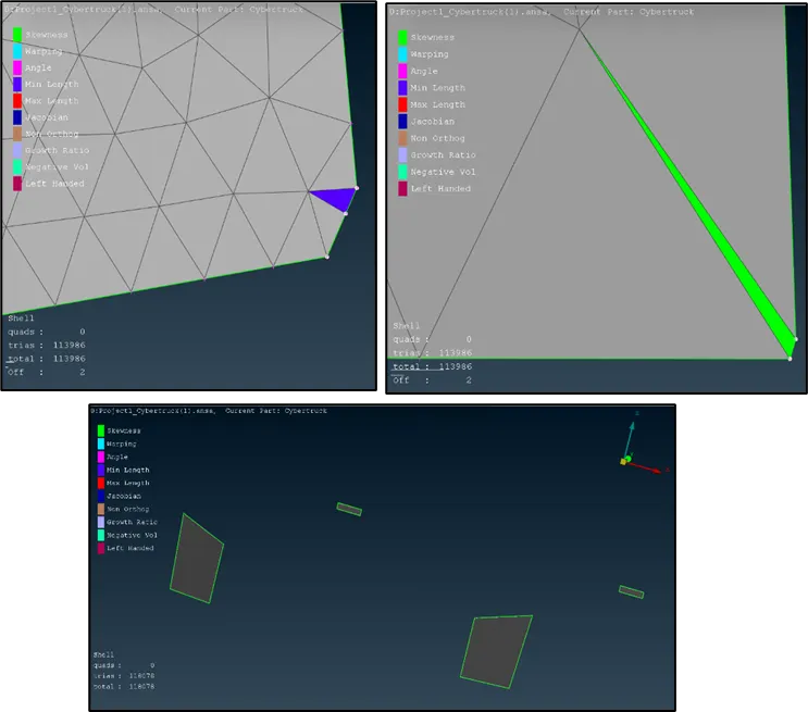
- There are 2 ‘off’ elements which are resolved using ‘move’ option.
2. WINDOWS:
- The mesh length is assumed as 5 mm with minimum and maximum length quality criteria as 3 mm and 7 mm
- The mesh is deployed using ‘spot mesh’ ‘visible’ option by isolating the PID.
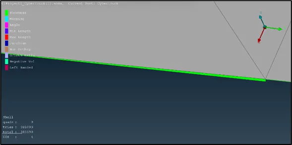
- The quality criteria have failed for skewness which is resolved using ‘move’ option.
3. TYRES:
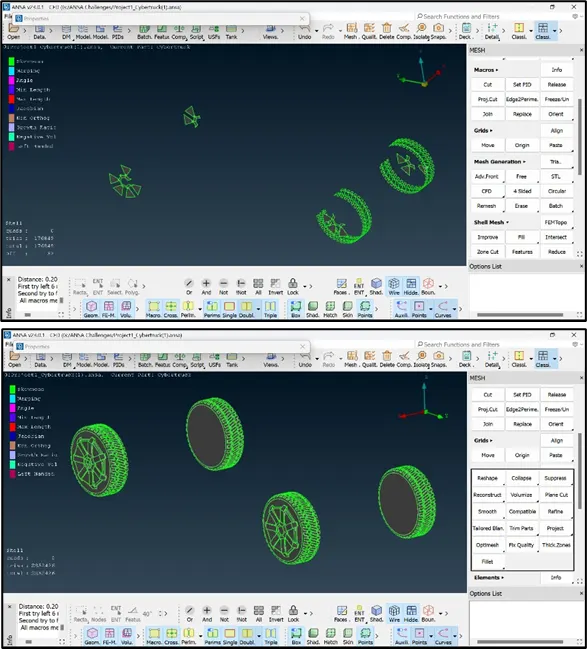
- The mesh length for the tyres is assumed as 3 mm. further, there are thinner sections on the inside of the tyre where the dimensions are 0.205 mm, hence the minimum quality criteria is taken as 0.2 mm and maximum is taken as 5 mm.
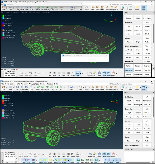
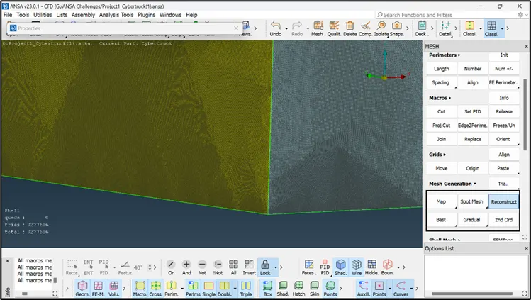
- The ‘reconstruct’ option has reduced the ‘off’ elements from 962 to 52 as shown. The ‘off’ elements are resolved by using ‘move’ option and ‘reconstruct’ option.
4. BODY:
- It can be observed that there are very thin sections on the interior of the body, which can cause difficulty during meshing. These thin sections ae resolved by deleting the respective surfaces and creating new surfaces.
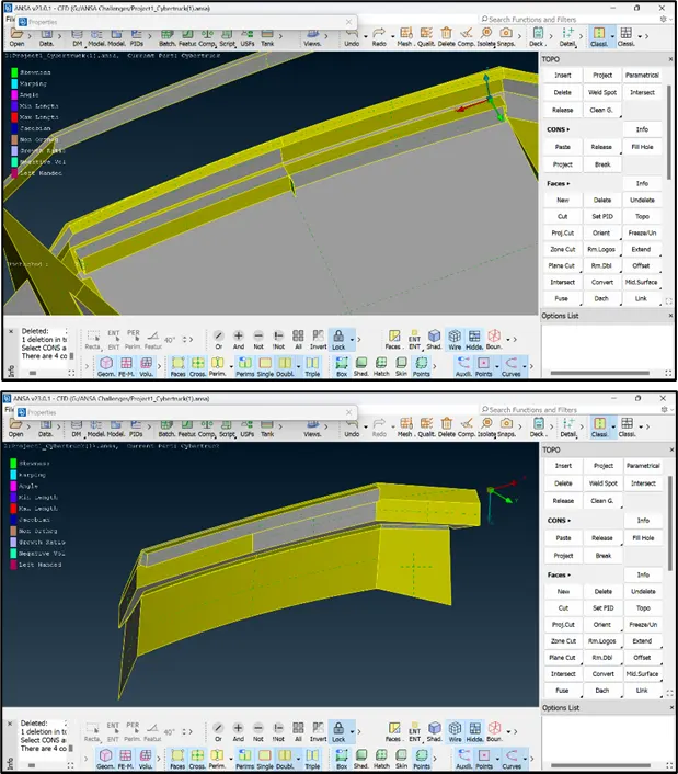
- The mesh length is taken as 5 mm and the quality criteria for minimum and maximum lengths is set as 1 mm and 7 mm.
- The body PID is connected to all the PIDs hence there are chances of mesh getting erased at the common perimeters of body and other PIDs.
- After specifying the quality criteria, the perimeters of the body PID are selected and the perimeters where the body PID intersects other PIDs are deselected.
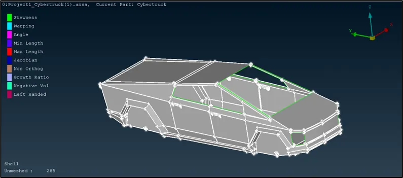
- The ‘off’ elements are resolved using ‘reconstruct’, ‘move’ and ‘reshape’ options.
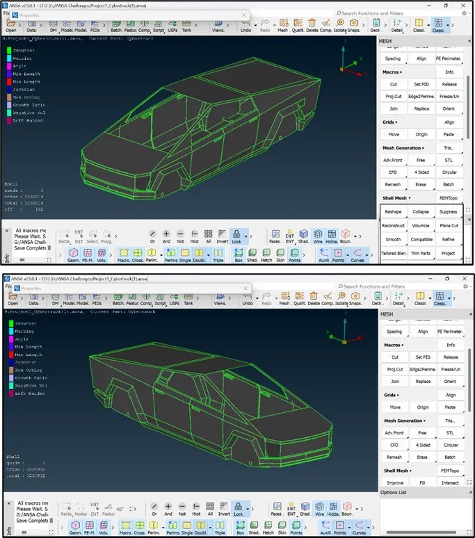
- All the PIDs are made visible using ‘all’ option, and it can be observed there are many ‘off’ elements, which are resolved using ‘reconstruct’ and ‘move’ options
CREATION AND MESHING OF WIND TUNNEL:
- The wind tunnel is designed with respect to the dimensions of the model. If the model has ‘x’ mm length, then the front face of tunnel must be at ‘4x’ mm distance, the rear face must be at ‘6x’ mm distance and the top face must be at ‘3x’ mm distance from the top point, the bottom face must be below the model with a considerable gap and the side faces of the tunnel must be ‘x’ mm on either side.
- The approximate dimensions of the car are as shown in image (length = 5865 mm and height = 1540 mm).
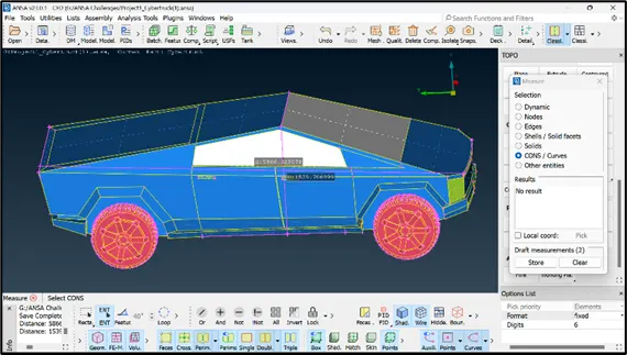
- Select an arbitrary point using ‘relative’ option in ‘points’ menu and set an arbitrary distance of -300 mm in ‘dz’.
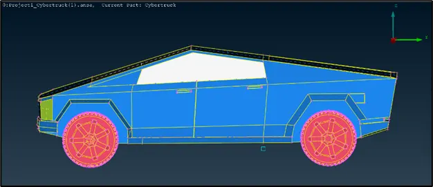
- Measure the distance between the created point and the node at the front part of the car. Add the distance (3798 mm) with the ‘4x’ mm distance (23460 mm) to obtain the front face end of the tunnel.
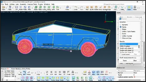
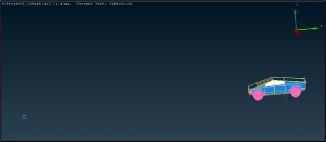
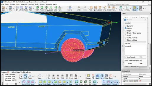
- The rear face of the tunnel is created using same procedure. The distance between the created point and the rear end point (2072 mm) is added to ‘6x’ mm distance (35,190 mm).
- The top face is created by selecting an arbitrary point (as shown) and selecting the y-axis distance as 17595 mm.
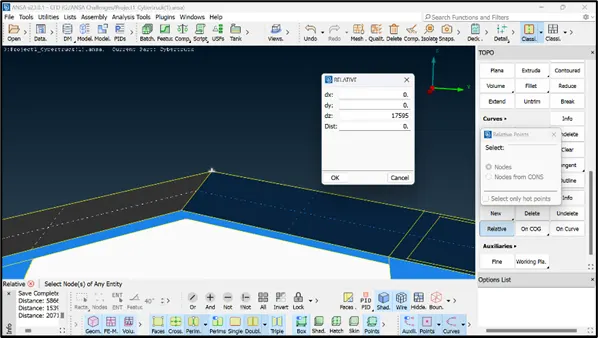
- The side faces of the tunnel are created at a distance of 5865 mm on by selecting both the points at the front and rear end.
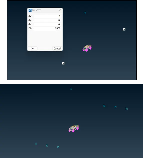
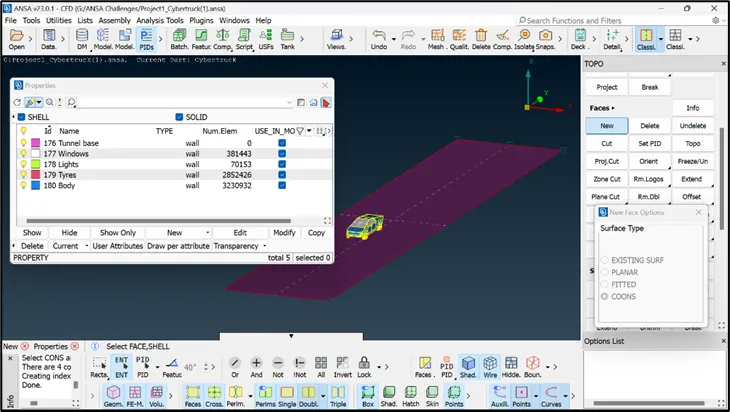
- The points are then converted to curves using ‘create’ option in ‘curves’ menu and selecting the end points to form a closed surface. The surface is then created using ‘coons’ option and is assigned a new PID under PID manager.
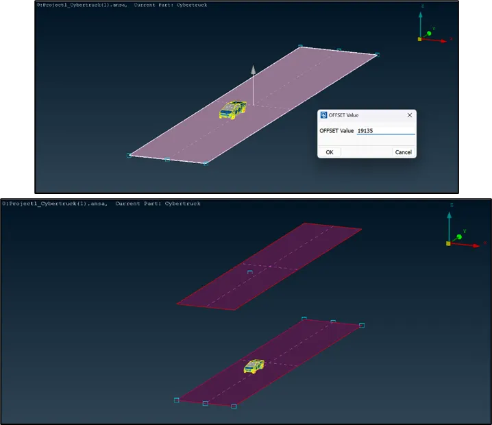
- The top surface is created using the base surface as a reference. The vertical distance between the bottom point and the car’s top surface (390) is added to ‘3x’ distance.
- To create top surface, click on ‘offset’ option in ‘faces’ menu, select the reference surface and enter the offset distance (19135 mm).
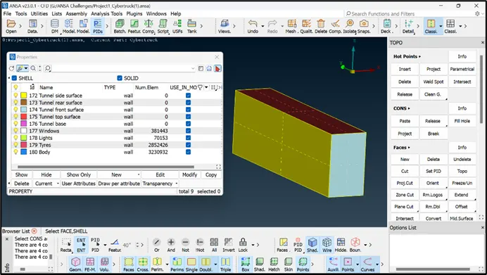
- Isolate the entire model using ‘not’ option and delete the created curves using the universal delete option.
- Create the remaining surfaces of the tunnel using ‘coons’ option. Also assign the respective PIDs to the surfaces under PID manager.
- The mesh will be assigned such that it is finer near the surfaces and coarser away from the surfaces. This is because the area of interest is near the model surface and this also helps to reduce the computational time.
- The top surface is isolated and the perimeters and macros are given a mesh length of 100 mm.
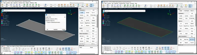
- Similar procedure is adopted for the bottom surface but with a mesh length of 20 mm.
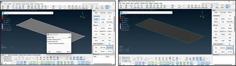
- The meshing along the height of the tunnel is to be varied from 20 mm to 100 mm, hence use ‘spacing’ option in parameters and select biasing as geometric
- The meshing along the height of the tunnel is to be varied from 20 mm to 100 mm, hence use ‘spacing’ option in parameters and select biasing as geometric.
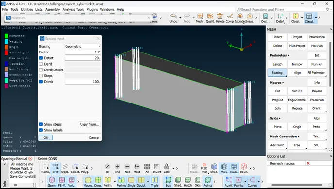
- All the other surfaces of the tunnel are then meshed one at a time to complete the surface meshing of the tunnel.
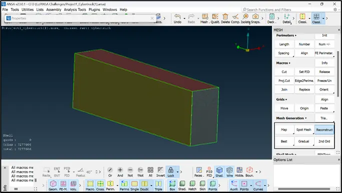
- It can be observed that the meshing is very fine as expected at the bottom and gradually becomes coarser along the height of the tunnel.
VOLUMETRIC MESHING:
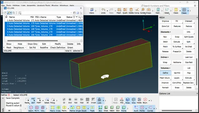
- Click on ‘define’ option in volumes menu and select whole database to define the volumes. Total 8 volumes are detected by ANSA, out of which only 1st volume is required (between wind tunnel and the cyber truck), hence delete the other volumes.
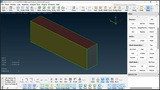
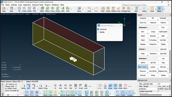
- To deploy volumetric mesh, use ‘Tetra CFD’ in ‘Mesh volumes’ option in ‘volumes’ menu.
RESULTS:
- The required geometrical clean-up and the surface meshing of the cyber truck model is performed.
- The wind tunnel with standard specifications has been created and surface meshed.
- The total tria (2D) mesh elements are found to be 1,38,12,414.
- The volume for the 3D mesh has been defined and due to lack of system capability, the volumetric mesh is not deployed.
Model setup file: https://drive.google.com/file/d/1Cq3ntkPweNipHmjsg7tImKu87yDsx5dy/view?usp=share_link