Week 2 Challenge : Surface meshing on a Pressure valve
AIM:
To perform geometrical topology clean-up for the pressure valve model and compare meshing results with 1 mm, 3 mm and 5 mm mesh lengths.
PROCEDURE:
- The first step before the meshing of any geometry is to ensure that the model has closed surfaces throughout.
- This is evaluated using the geometry check option under check feature in ANSA. The results show any available errors (single cons particularly highlighted in red) which must be avoided to form a volume for proper meshing in later stages.
- Further, highlighting the single cons we can see them and make necessary topological corrections.
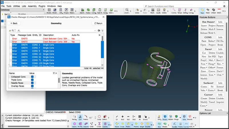
- In the next step using ‘New’ feature in ‘Faces’ menu we can perform the geometrical corrections to obtain a volume for meshing.
- This can be done by different ways:
- Existing surfaces: here the closed geometry can be obtained by selecting the single cons individually and then selecting the cross hatch of the face where the correction is to be made.
- Coons: in this type instead of selecting individual cons we can enable loop option and select the single cons at once having a loop which can perform the geometrical correction.
- Fitted: this feature also can be used in a similar manner as that of coons.
- Planar: this is similar to existing surface feature where the hole present on a surface can be patched.
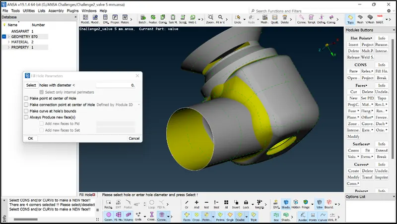
- Fill hole: this is an independent feature under CONS menu. The area to be filled (circular or rectangle) is selected or the diameter can also be entered (if known) to form a closed surface as shown.
- One of the important things to be considered while topo clean-up is to ensure that the selected single cons have a closed surface and same length. To ensure that we can select the cons in wireframe mode by CTRL shift and double clicking a con.
- Also, there is a possibility to use double cons to create a closed surface. These above steps are followed in general to obtain a closed surface for correct meshing process.
- Further, there are chances of presence of smaller areas where the mesh length is greater than the distance between the lines enclosing that area. Such lines are identified and deleted using cut option by right click.
PID creation and assignment:
- In the PID manager, right click then select ‘new’, ‘P-shell’, ‘P-shell’ which opens a dialog box, and enter the name for the PID, example outlet and as per requirement.
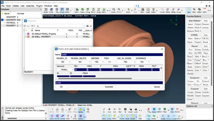
- The colours of the PID can be changed by double clicking on the palette and selecting another colour and click OK.
- In order to assign the PID, select apply by right click on PID created. Now select the cross hatch of the surface which has to be assigned and right click.
- Further, the body component of the assembly cannot be assigned directly as it contains a greater number of individual components. Hence, we isolate the body using ‘OR’ option with ‘PID region’ enabled. This ensures that the body is continuous and can be assigned for a PID. Later, the isolated body is assigned with the PID (as shown in figure below) as explained in previous step.
- Further the PIDs for spring, column, base, valve head are created and assigned as explained above.
- It can also be seen that the PID 36 is invalid and can be deleted as all the components in the assembly are assigned as per the requirement. But, since some of the faces were deleted during the topology clean-up, it cannot be deleted which are highlighted in the image below.
- These can be retrieved by clicking on the cross hatch of the highlighted surfaces. Middle click on surface shows that there is a glitching on the outlet surface as shown in image 5. This is due to the overlapping of surfaces of outlet and the shell property PID 36.
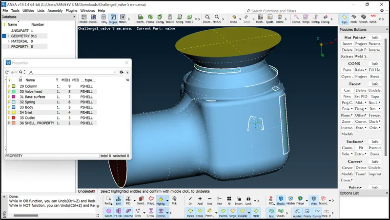
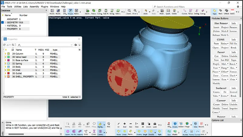
- After the undelete, it is mandatory to use ‘topo’ option to connect the surfaces. This completes the topological clean-up of the component and it can be continued with meshing.
- The mesh length is assigned using length option in perimeters feature of mesh deck. The perimeters and the macros are assigned with the mesh length as required.
- In the mesh parameters, the target length is set, element type is set as tria and the maximum and minimum target length according to the mesh length used.
CASE 1: Target length = 5 mm
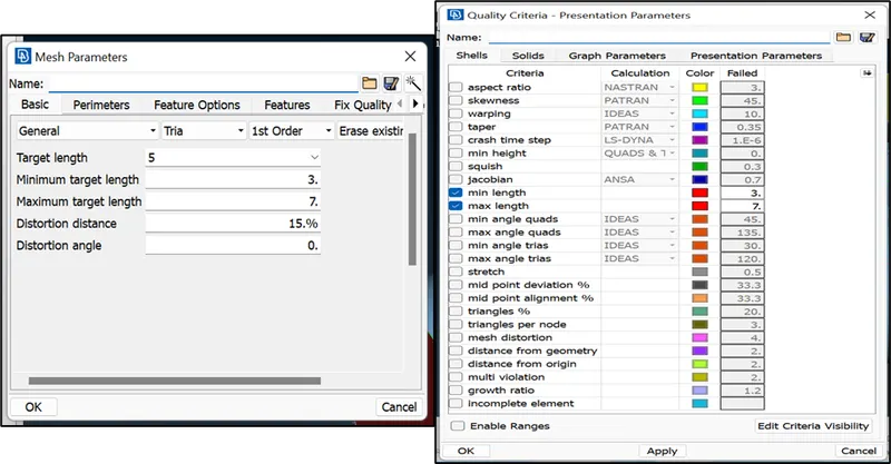
- Considering the mesh length as 5 mm we can set the maximum and minimum target length as 7 mm and 3 mm in both mesh parameters and quality criteria as shown.
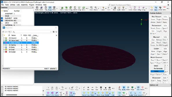
- In the next step we use spot mesh feature and can either mesh the entire component at once or selecting one surface at a time for a better understanding of meshing.
- Click spot mesh, select the con of the surface to be meshed then right click to apply the mesh as shown. Sometimes, there are certain surface which can be difficult to mesh, then we can use PID manager to isolate that surface by using show only option. Further, using visible option under spot mesh we can easily mesh the required surface.
- During the meshing of the spring, we can observe that since the target length is greater than the diameter of the spring, it is not meshed as per the requirement and the element size can be considered as coarser, which can cause inaccuracy in the CFD analysis to be carried out.
- Similar kind of inaccurate meshing can be seen in different locations of model where the target length is greater than the length/diameter of the component
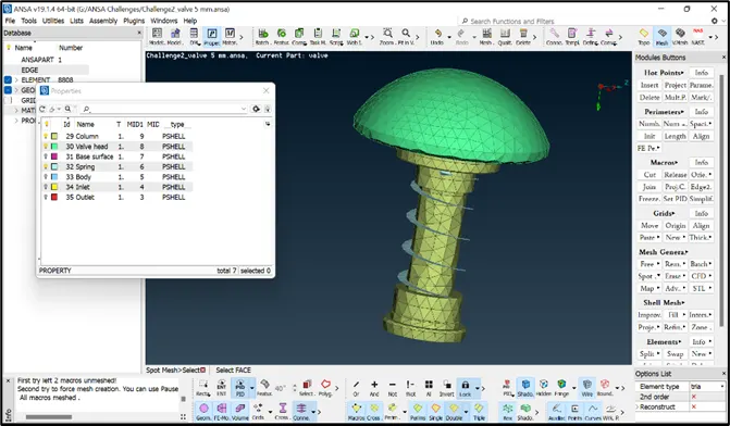
- This shows that the efficiency of the mesh is purely dependent upon the target length. Smaller the target length there will be a greater number of elements with smaller size.
- Now we isolate the components individually and by altering the target length lesser than the mesh length (3 mm or lesser in this case) and continue with the meshing.
CASE 2: Target length = 3 mm
- In this case the target length is set as 3 mm and the minimum and maximum target length is set as 1 and 5 mm respectively.
- It can be observed that some of the areas of the body of the component are observed to have an irregular meshing as shown in fig 9. It can also be observed that the meshing elements are comparatively more in number as compared to that of the meshing obtained by 5 mm of target length.
- From this it can be concluded that 3 mm target length meshing has higher number of elements which can contribute to a higher efficiency of meshing.
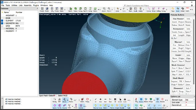
- Moreover, it can be observed that the meshing become more uniform in case of 3 mm target length than 5 mm comparatively. The element size and the number of elements (23926) are also higher in comparison with the later (8808) by approximately 3 times.
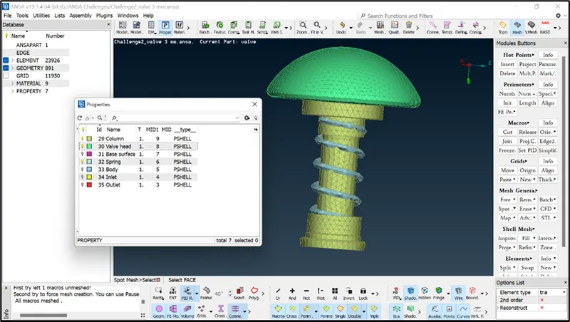
CASE 3: Target length = 1 mm
- In this case the target length is set as 1 mm and the minimum and maximum target length is set as 0.5 and 2 mm respectively.
- The meshing shows that there is more uniform meshing and the elements are very finely segregated which can give a more efficient meshing.
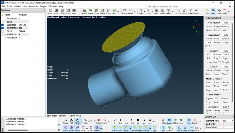
- Also, the inner parts of the assembly are finely meshed and a uniform surface can be observed.
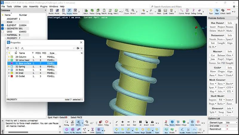
- It can be observed that the element size is very fine and the surfaces are more uniform compared to the other cases. The number of elements has increased to 2,10,004 which is approximately 9 times and 24 times than that of meshing with 3 mm and 5 mm target lengths.
- Finally, it can be concluded that the if the target length is smaller then the element size is smaller and there are larger number of elements which leads to a higher meshing efficiency.
LEARNING OUTCOME:
- Gained knowledge about the geometry check and its importance prior to meshing.
- Gained knowledge and hands on experience in geometry clean-up using ‘face’ and ‘fill hole’ option to create a closed surface suitable for an accurate meshing.
- Understood the importance of uniform geometrical surfaces that must be present before meshing.
- Gained knowledge about the PID creation and PID assignment to the components.
- Understood the importance of mesh target length and minimum and maximum target length during meshing, and its role in improving the overall efficiency of component’s meshing.
RESULTS:
The meshing of a pressure valve has been carried out with 3 different target lengths and the results obtained are as follows:
- The meshing of the components in the assembly is found to have a smaller number of elements and coarser elements with 5 mm of target length. It is also observed that at many locations of the assembly the meshing is improper as the length/diameter of the locations are lesser than that of the target lengths. This leads to an inefficient meshing overall.
- The case with 3 mm of target length has comparatively lesser locations with improper meshing but has a greater number of elements (approx. 3 times more) and the meshing can be considered as a normal mesh. Moreover, the meshing efficiency has also increased as the target length has decreased.
- The third case has a very fine meshing and very high number of elements compared to both the previous selected target lengths. The meshing of the entire assembly is observed to have a near exact uniform surface throughout having maximum meshing efficiency.
CONCLUSIONS:
- The overall efficiency of the component meshing depends purely on the target length assigned during meshing.
- Smaller the target lengths more will be the elements, smaller will be the size of the elements and higher will be the meshing efficiency which will lead to more accurate results during CFD analysis and vice versa.
- The conclusion is that the meshing made with the target length of 1 mm is the best and provides the best meshing efficiency since it has higher number of elements and finer segregation of components which will provide more accurate results.