Week 4 Challenge : CFD Meshing for BMW car
WEEK 4: CFD MESHING OF BMW M6 CAR WITH A WIND TUNNEL
AIM:
To perform the geometrical clean-up and mesh the BMW M6 model with the given target lengths and perform the volume meshing of the wind tunnel.
- Body - 3 mm
- Lights - 4 mm
- Grills - 1 mm
- Rims and Tyres - 2 mm
- Optical Rear-view mirror - 2 mm
- Window - 2 mm
- Silencer - 3 mm
- Logo - 1 mm
PROCEDURE:
- The model is imported in PID mode and if it contains single cons entirely, it is minimised using ‘TOPO’ option by selecting the whole model followed a middle mouse click.
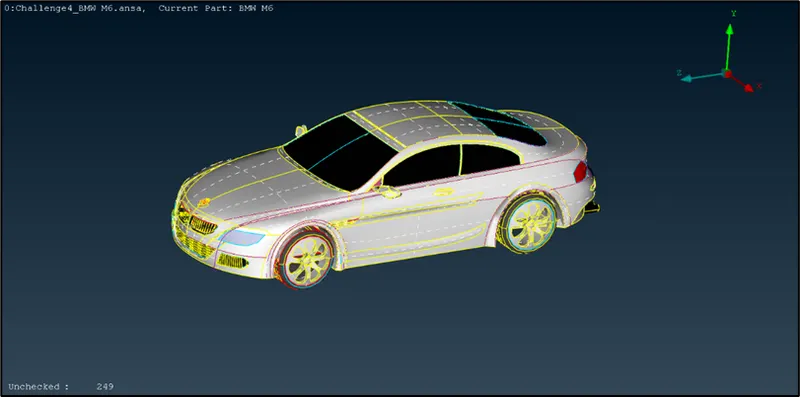
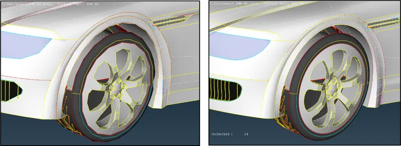
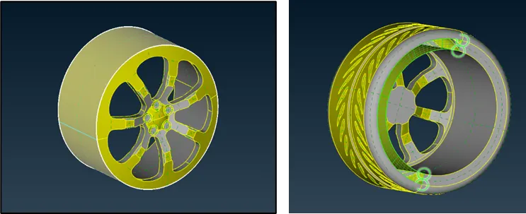
- Several components of the car are found to have deviated from their actual shape which is due to the cons resolution. To overcome this, select mesh mode, select length option in perimeters and enter the mesh target length as 1 mm in both perimeters and macros.
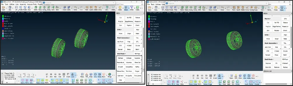
- This ensures that the components of the model have their respective ideal shapes. The below images show a comparison of car wheels before and after performing the cons resolution.
- The similar process can be carried out using ‘Fine’ option in ‘Auxiliaries’ menu but it will be a time-consuming process.
- Since the geometry is a complex one, there is a provision in ANSA that we can perform topo clean-up, meshing and the required operation only on one half of the model and using symmetry feature replicate it to the other half. To achieve this the half of the model is deleted using universal delete option.
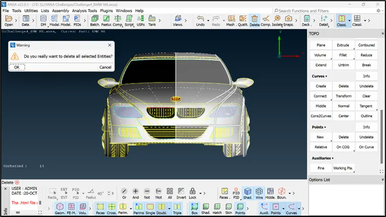
- The present single cons are converted to double cons using ‘paste’ option.
- The objective is to create the car into a single volume and imply it with volumetric mesh. Hence, the inner parts of the car can be deleted and only the outer surface parts are required. This is performed using universal delete option.
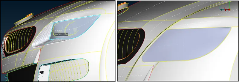
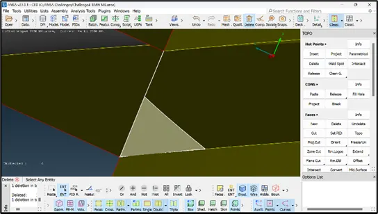
- The grill part of the car is also checked for unnecessary parts and are deleted. As shown in the image to delete the required surface, first project the con on the surface of the grill. Then delete the hot-points so as to get a closed surface and delete the surface using universal delete option.
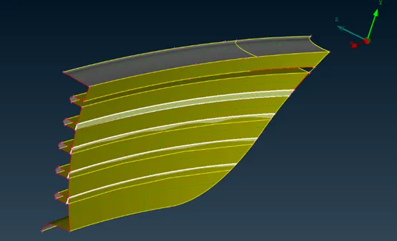
- Similarly, all the fins at the grills can be deleted at once by using project option and later deleting it using universal delete option as shown below.
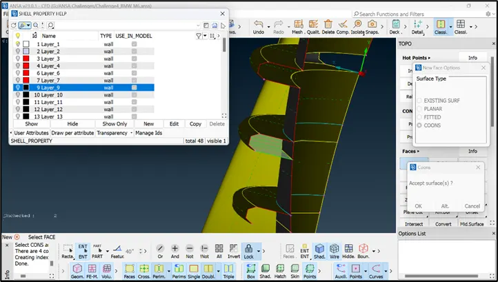
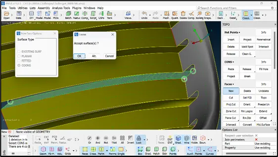
- After deletion, it is observed that there are gaps between fins and the grill surface. The gaps are patched by deleting the older surfaces and creating a new surface by using ‘coons’ option. Further, due to change in the geometry, the PID matching the newly created surface is selected by double click.
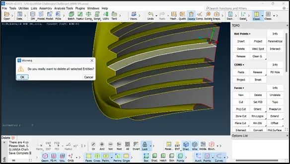
- At some locations the surface isn’t intersecting to the ends, so the following procedure is followed:
- The triple con intersecting the fin and the grill is released using ‘release’ option and the surface is deleted and the unnecessary hot-points are also deleted.
- The hot-point at the end of single con is projected on the end surface and cut option used to isolate the surface and it is deleted as shown.
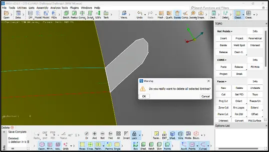
- The obtained double con is released which isolates the fin surface on the grill, which is deleted. Then create a new surface using ‘coons’ option by selecting the appropriate cons as shown in fig.
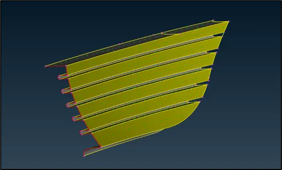
- The extra surfaces and the redundant hot-points are also deleted to obtain the finished fin and grill geometry.
- The triple cons on the grill are deleted using the universal delete option.
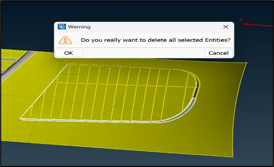
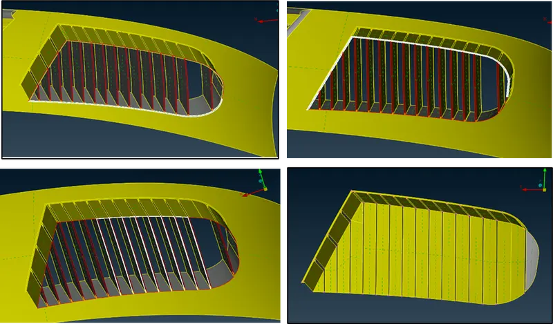
- The ribs of the grill are formed into a volume by deleting the inner surfaces as shown in image.
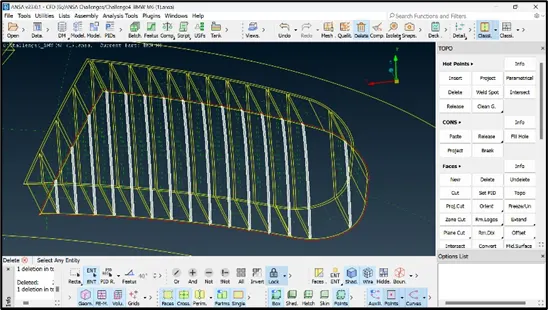
- In the next step, create new surface at the edge of the ribs by using ‘cut’ option. Delete the created surface using ‘delete’ option. The open geometries are then closed using ‘fill hole’ or ‘coons’ option.
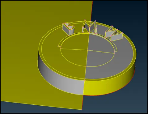
- The logo of the car is isolated and the triple cons are eliminated by deleting the isolated surfaces. This creates a gap on the outer surface of the logo which is created using ‘new’ option and ‘coons’ feature.
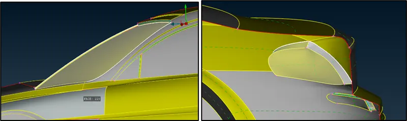
- The wind-shield of the car (front and back) having triple cons represents additional surfaces which are deleted using ‘universal delete’ option.
- After deleting the duplicate surfaces on the grill (below logo), the surface is created by projecting the single con individually on the grill surface and the ribs. The project cut option is used to cut the ribs.
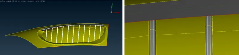
- The ribs that are not required are deleted and the entire grill is developed into a surface using smaller surfaces using ‘coons’ option.
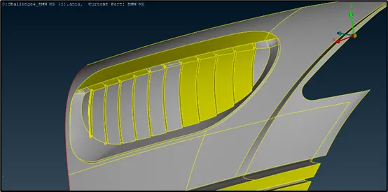
- It can be seen that near the tyre, the intersection of the surfaces is not proper to select and delete a surface. To eliminate the required surface, use intersect option (shown in fig). After intersection, the triple cons show the presence of overlapped surfaces and the surfaces which form a volume other than the car’s volume are deleted.
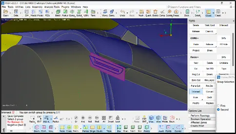
- The surfaces having no contact are rectified and deleted using of ‘cut’ option and ‘delete’ option respectively.
- The single cons having no connections to the surfaces are extended to the adjacent surfaces to form a complete surface to facilitate easier deleting of surfaces.The single cons available are made double cons using ‘paste’ option and all the surfaces at the inside are closed to from a single volume
- The inner side has a surface which is not isolated. To isolate this, first use ‘extend option to extend the single con on to the required surface. Now create a new surface using ‘coons’ option and isolate the required surface and delete it.
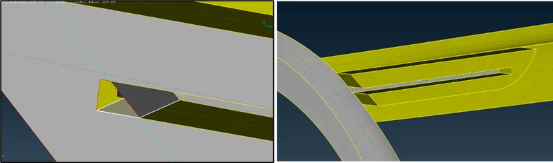
- The mirror is isolated using ‘i-not’ option and the outer surfaces of mirror are hidden to ease the deleting of the overlapping surfaces present in the inner side of mirror.
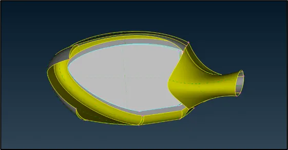
- Since the mirror will also form a separate volume, delete the circular surface and extend it to the surface of the window shield to form an overlapped surface. Delete the overlapped surface to include mirror as a single volume with the car.
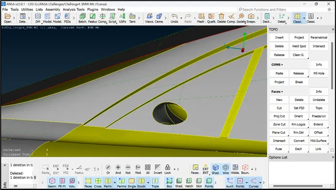
- The tyre is isolated from the car body using ‘I-not’ option enabling ‘PID region’ mode. The view is locked and the top surface of the tyre is hidden using ‘not’ option.
- The overlapped surfaces are deleted using the ‘delete’ option.
- The resolve the single cons, the surfaces adjacent to them are deleted and a new slant surface is generated using ‘coons’ option.
- Repeat the same procedure for the other tyre.
- The rear parts of the car having duplicate surfaces are deleted using ‘delete’ option.
- The wheels are intersecting to the base of car which are deleted. The single con obtained is then extended on to the base surface. To facilitate easier deletion, the surfaces are intersected using ‘intersect’ option as shown in figure.
- The surface covering the tyre is then deleted and a new surface is created.
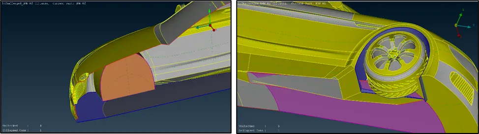
- Before deleting the base surface of the car is deleted, use ‘cons2curves’ option in ‘curves’ menu and select the single con and middle click. Enable the curves option at the bottom of the interface and delete the excess curves.
- The surface is then deleted and while creating a new surface it is easier since the blueprint of the single con (purple colour in image) is visible.
- To create a uniform surface, again use ‘cons2curve’ option on single con below the wheel, insert a hot-point’ on the previously created con using ‘cons2curve’, make a cut on the rectangular surface and delete the surface.
- The new surface is generated and the selected surfaces (as shown) are deleted.
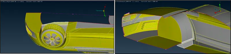
- Since the base of the car has many overlapped surfaces and the geometry is complicated, create curves to further create the simpler geometry.
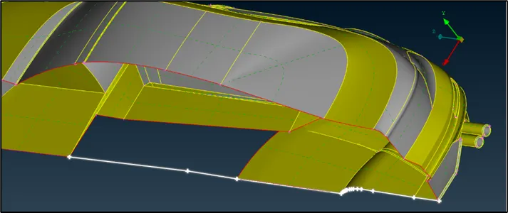
- After the geometry creation, the duplicate surfaces are deleted and using ‘delete’ option in ‘curves’ the curves are also deleted.
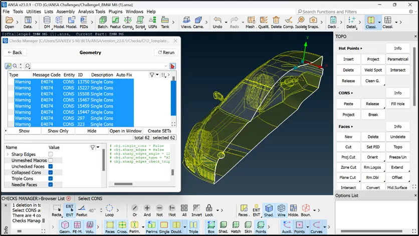
- The geometry check is done in order to asses the presence of errors. A triple con is found at logo part. The triple con and the double con adjacent to it are released and the extra hot-points are deleted followed by applying ‘topo’ on that region.
- The locations containing needle like structures are smaller surfaces which are deleted. The collapsed cons are also identified and the cons are released to form single cons, the extra hot points are deleted and the ‘topo’ is performed to the respective region. The geometry check is run to ensure only the required single cons (on the symmetrical edge of the car) are present.
- Additional PIDs are created and the components are assigned with the respective PIDs.
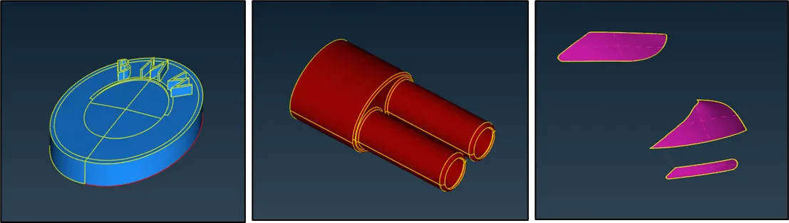
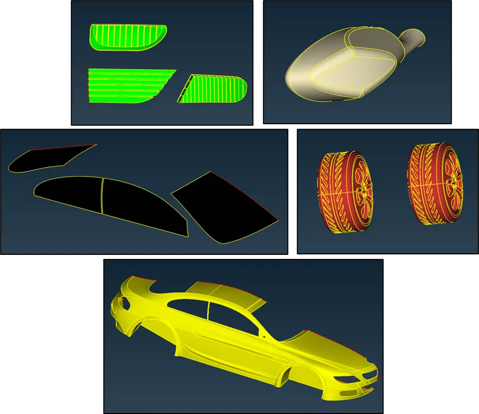
- The additional PIDs are deleted using ‘compress’ option.
- Select the ‘open foam’ deck and under ‘topo’ mode click quality criteria and enter the quality criteria for the meshing.
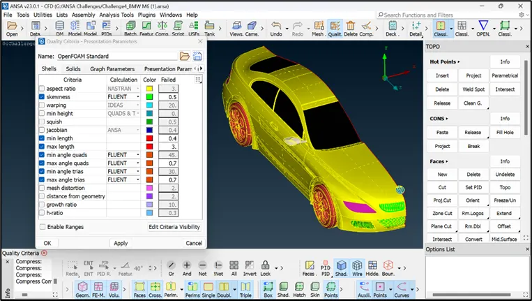
- Each of the PIDs are individually checked before meshing for their minimum and maximum target lengths based on the mesh lengths given in the problem.
- The target length for the body is selected as 3 mm, so the maximum and minimum target lengths are 5 mm and 1 mm which are entered in the quality criteria and the mesh parameters.
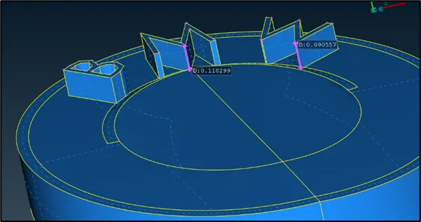
- The quality criteria fails if the mesh element has the length greater than maximum or lesser than minimum length. Hence identify the locations visually which have smaller surfaces where the criteria might fail and right click the cons using ‘cut’ option.
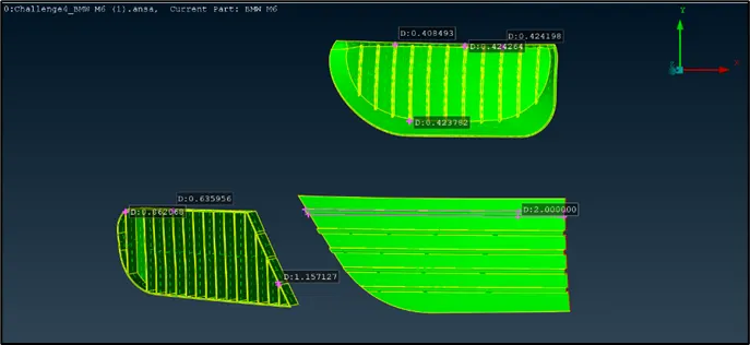
- The grills target length is 1 mm, hence the minimum and maximum target lengths will be 0.5 mm and 2 mm. As the measurements indicate the minimum length between 2 lines is 0.4, we can set the minimum target length as 0.4 mm for the grills.
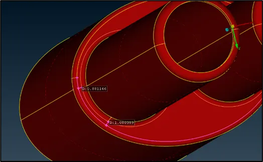
- Similarly, for the silencer part there are locations where the minimum target length will fail. Hence, use cut option to create cuts so that the distance between the nodes and cons is acceptable for minimum target length.
- The logo part has a stepped surface with sharp curvature where the quality criteria will fail, hence delete the surface and create a new surface using ‘coons’ option. The minimum quality criteria are failing at the ‘M’ and ‘W’ locations. Hence delete and create a new surface at those locations. Further the minimum criteria are also changed from 0.5 mm to 0.3 mm.
SURFACE MESHING:
1. LOGO:
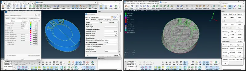
- The mesh length is given as 1 mm; hence the quality criteria and the mesh parameters are set as shown in image. The mesh is assigned using spot-mesh visible option. The view is set to ‘hidden’ and entity mode is enabled.
- The allocated mesh shows 37 ‘off’ (failed) elements which are further reduced to 1 using ‘reconstruct’ option. Further, the location of the off element is identified and on performing the mesh and reconstruction again the off elements are reduced to 0 to obtain a perfect mesh.
2. GRILLS:
- The mesh lengths and the quality criteria are the same as that of the logo, hence the mesh is deployed on the grills and it shows a total of 2 off elements after reconstruction. The location of ‘off’ elements are identified and the surfaces are reconstructed.
- The mesh is again deployed using spot mesh visible option and reconstruct option s used to eliminate all the off elements to achieve a perfect mesh of 98830 tria elements.

3. WINDOWS:
The given mesh length is 2 mm, hence quality criteria and the mesh parameters are assigned with minimum and maximum target length as 1 mm and 3 mm. The mesh is assigned using ‘spot mesh’, ‘visible’ option. The reconstruction shows no off elements with total of 61361 tria elements.
4. LIGHTS:
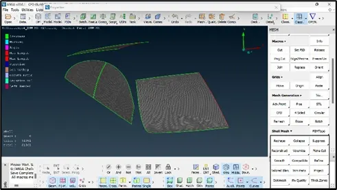
The mesh length and the quality criteria are given as 4 mm, 3 mm and 5 mm. The mesh deployed shows 8 off elements. The off elements are removed using ‘move’ option with ‘guided’ feature in ‘grids’ menu. The node is selected and moved around till the mesh criteria is agreed to get a perfect mesh.
5. TYRES AND RIMS:
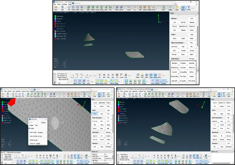
The mesh length of 2 mm and the minimum and the maximum target length of 1 mm and 3 mm is assigned in the quality criteria and the mesh is deployed using ‘spot mesh’. The reconstruct option reduces the ‘off’ mesh elements to 19. The move option in grids menu is used to manipulate the nodes and obtain a perfect mesh with 150518 tria elements.
6. SILENCER:
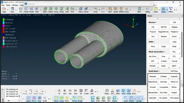
The mesh length of 3 mm and the quality criteria of 1 mm (minimum) and 5 mm (maximum) is set. The mesh is assigned using ‘spot mesh’ visible option to give 8564 tria elements and 1 off element. The reconstruction feature is used to obtain a perfect mesh with 8624 tria elements.
7. OPTICAL REAR VIEW MIRROR:
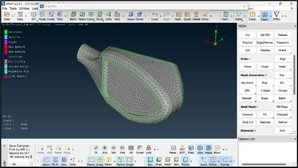
The mesh length of 2 mm and the quality criteria of 1 mm (minimum) and 3 mm (maximum) is set. The mesh is assigned using ‘spot mesh’ visible option. The reconstruction feature gives 4620 tria elements and 2 off elements. The ‘move’ option is used to obtain a perfect mesh with 4644 tria elements.
8. BODY:
- The mesh length of 3 mm and the quality criteria of 0.4 mm (minimum) and 5 mm (maximum) is set. The body is the PID which is connected to all other PIDs hence there is a chance of erasing of mesh due to different mesh lengths at different PIDs.
- Use ‘lengths’ option in perimeters and select the body PID. Deselect the edges where there is a chance of erasing of mesh in other PIDs. Middle click and assign the mesh length of 3 mm to perimeters and verify if any of the mesh is erased.
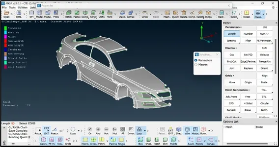
- Now using ‘spot mesh’ select option in PID mode, select the car body and middle click to apply the mesh.
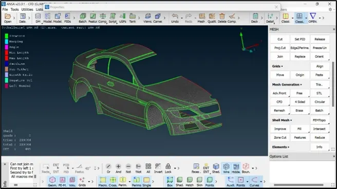
- All the PIDs are made visible on the interface and by using ‘reconstruct’ feature the ‘off’ elements are reduced to 399.
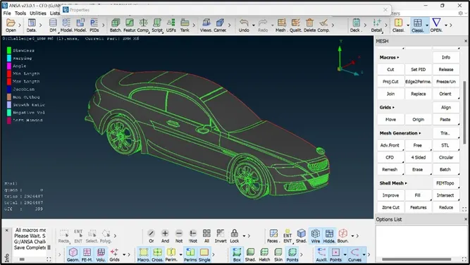
- The off elements are resolved using ‘move’ option and are reduced to 383 off elements. Applying ‘reconstruct’ again leaves only 1 off element which is resolved using ‘move’ option.
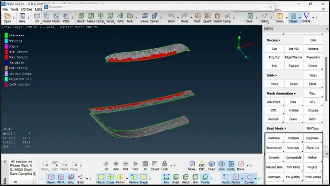
- The total elements in the model (half) with surface mesh is 2927138 tria elements.
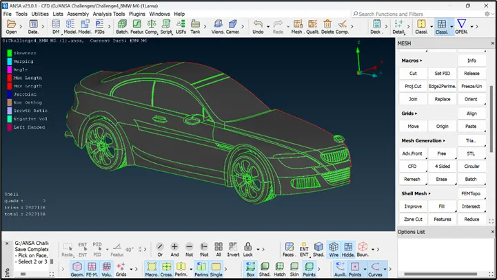
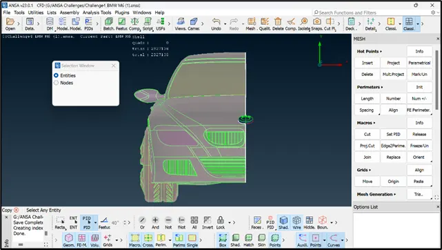
- The next step is to assign symmetry option to the meshed model. Select ‘top view’ in views menu.
- Click on ‘transform’ and select ‘copy’ option. Under entities select the entire geometry that is to be mirrored and deselect the logo PID.
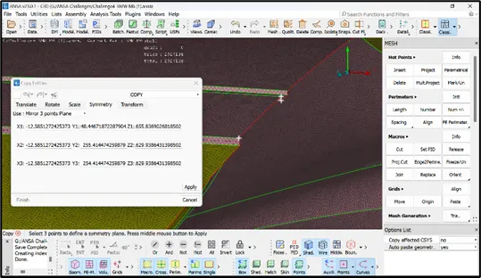
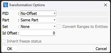
- Middle click and in the dialog-box select ‘symmetry’ option and select ‘mirror 3-point plane’. Select 3 points as shown in image and middle click. Accept the default settings in the transformation options and click OK and ‘finish’ to apply the symmetry.
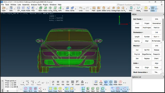
- The complete car model with 5849769 tria elements is as shown in image. Also, as we switch to ‘topo’ mode there is a presence of 3 single cons.
- The single cons are resolved using ‘paste’ option (at the front and back window shields). Similarly, using ‘paste’ option at the logo part erases the mesh partly. Hence the quality criteria and the mesh parameters for the logo is given and by selecting the correct entity for meshing, the erased mesh is deployed.
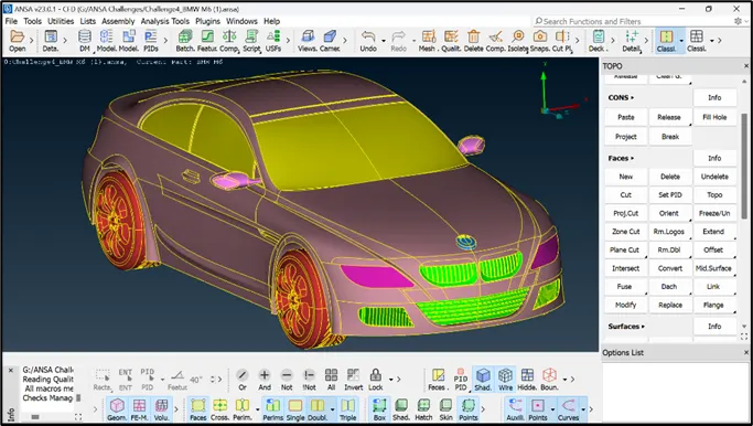
CREATING AND MESHING OF WIND TUNNEL:
- Wind tunnel is a medium where the wind flow over the car can be analysed in CFD applications.
- The wind tunnel is designed with respect to the dimensions of the model. If the model has ‘x’ mm length, then the front face of tunnel must be at ‘4x’ mm distance, the rear face must be at ‘6x’ mm distance and the top face must be at ‘3x’ mm distance from the top point, the bottom face must be below the model with a considerable gap and in the top view, the side faces of the tunnel must be ‘x’ mm on either side.
- Select ‘relative’ option in ‘points’ menu and select a point at the base and in Y-axis set an arbitrary distance of -75 mm.
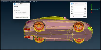
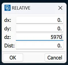
- Measure the distance between the created point and the node at the front part of the car. Add the distance (770 mm) with the ‘4x’ mm distance (5970) to obtain the front face end of the tunnel.
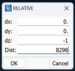
- The rear face of the tunnel is created using same procedure. The distance between the created point and the rear end point (496 mm) is added to ‘6x’ mm distance (8296 mm).
- The top face is created by selecting an arbitrary point (as shown) and selecting the y-axis distance as 3900 mm.
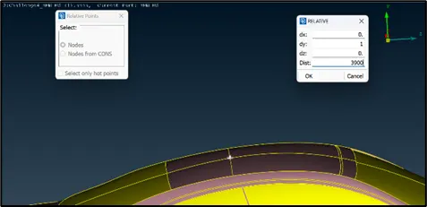
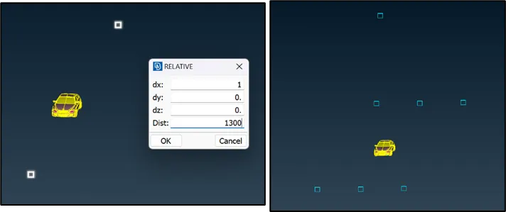
- The side faces of the tunnel are created at a distance of 1300 mm on by selecting both the points at the front and rear end.
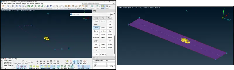
- The points are then converted to curves using ‘create’ option in ‘curves’ menu and selecting the end points to form a closed surface. The surface is then created using ‘coons’ option and is assigned a new PID under PID manager.
- The top surface is created using the base surface as a reference. The vertical distance between the bottom point and the car’s top surface is measured (390) and is added to ‘3x’ distance.
- Click on ‘offset’ option in ‘faces’ menu, select the reference surface and enter the offset distance (4200 mm).
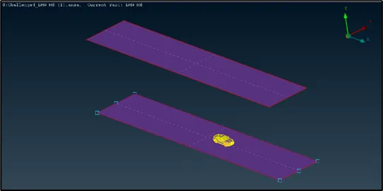
- Isolate the entire model using ‘not’ option and delete the created curves using the universal delete option.
- Create the remaining surfaces of the tunnel using ‘coons’ option. Also assign the respective PIDs to the surfaces under PID manager.
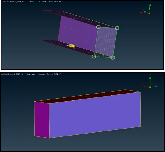
- Since the area of interest will be to study the wind flow only near the surface of the car, the mesh will be assigned such that it is finer near the surfaces and coarser away from the surfaces. This also helps to reduce the computational time.
- The top surface perimeters and the macros are selected and the mesh length is given as 100 mm and the bottom surface perimeters and the macros are assigned a mesh length of 20 mm.
- The meshing along the height of the tunnel is to be varied from 20 mm to 100 mm, hence use ‘spacing’ option in parameters and select biasing as geometric.
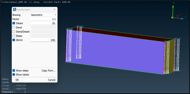
- The bottom surface is isolated and meshed by assigning minimum and maximum length of 15 mm and 25 mm, the top surface is isolated and meshed by assigning minimum and maximum length of 15 mm and 25 mm. The front, rear and the side surfaces are meshed one surface at a time.
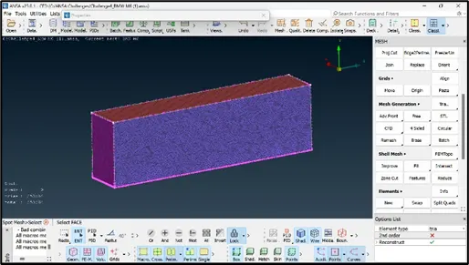
VOLUMETRIC MESHING:
- Click on define option in volumes menu and select whole database to define the volumes. Total 8 volumes are detected by ANSA, out of which only 1st volume is required, hence delete the other volumes.
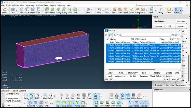
- The volumetric mesh is assigned using ‘volume mesh’ option and selecting ‘tetra CFD’ option.
RESULTS
- The topo clean up and the surface meshing with different mesh lengths as required by the PIDs is performed.
- The tunnel is prepared according to the standards and the volumetric meshing is asssigned to the tunnel.
https://drive.google.com/file/d/1dmRJkoYLe3GB-NQsXPpNASRRAPm7t2To/view?usp=share_link