Week 6 - CHT Analysis on a Graphics card
Aim:
To perform a steady-state conjugate heat transfer analysis on a model of a graphics card for three different velocities 1m/sec,3m/sec and 5m/sec for two different mesh
Background theory:
With the power consumption of computer graphics cards having increased significantly in recent years, it is now more important than ever to effectively manage cooling and heat dissipation in these important components.
Graphics cards are cooled by cooling fans and heat pipes etc.
Procedure:
Case-1- Base line mesh - velocity = 1 m/s
1. Import the Geometry to spaceclaim
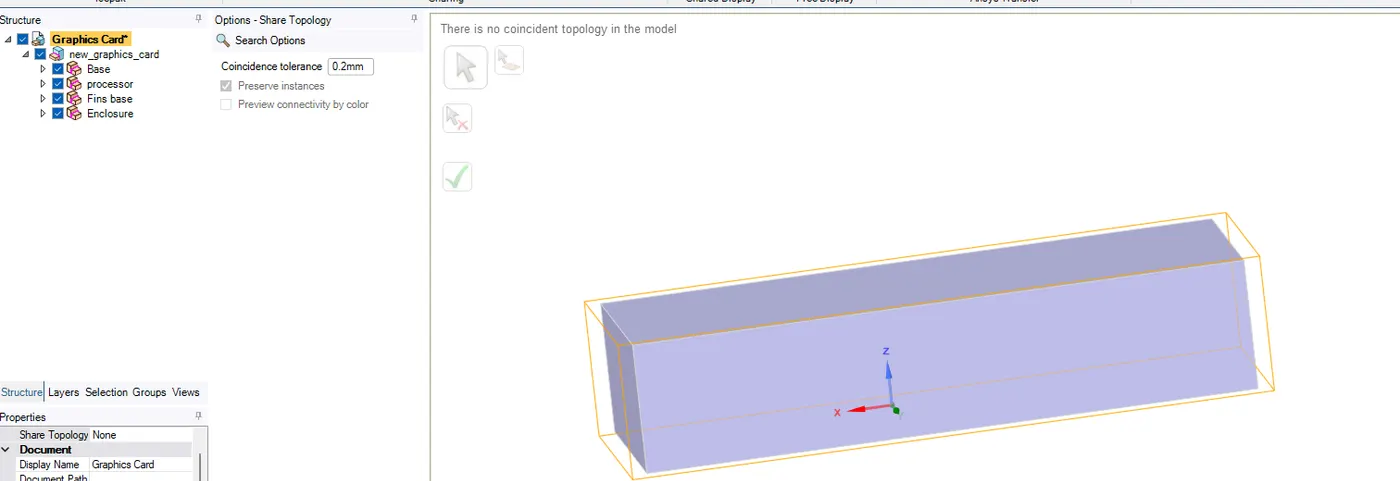
2. Prepare geometry for conformal mesh .
WORKBENCH->SHARE TOPOLOGY
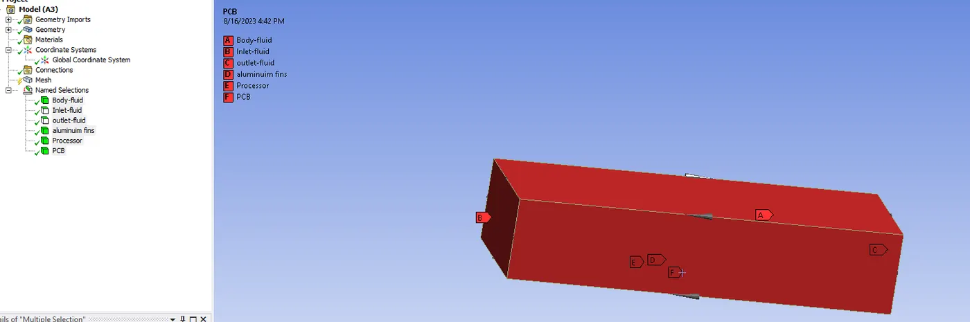
3. Bodies and faces are named
4. Checking for conformal mesh
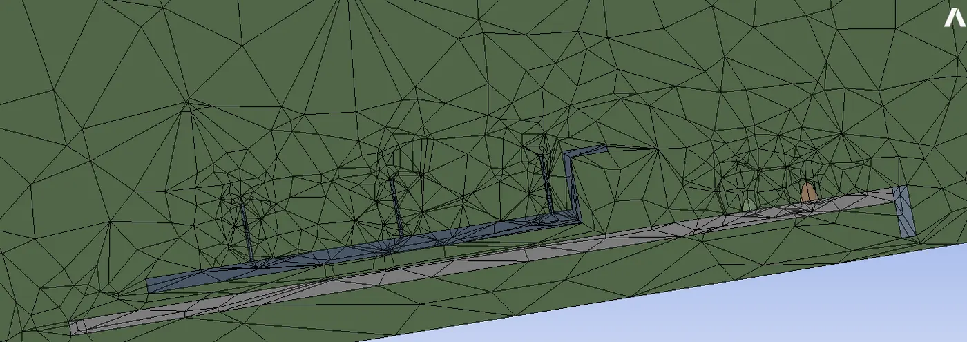
Since shared topology is done, conformal mesh is produced
5. Materials and properties
With refer to (1)
Properties are at NTP
- Processor - Silicon
Thermal conductivity = 148 w/mk (2)
heat capacity = 0.71 j/kgK (3)
density = 2330 kg/m3 (4)
2. PCB - Epoxy resin
Thermal conductivity = 0.2 W/mk (5)
heat capacity = 1110 J/kgK (6)
density = 1200 kg/m3 (7)
3. Fins - Alumium
(used fluent database)
6. Boundary conditions
Inlet velocity = 1 m/s
Assume that this is 50W processor and 49 w heat is generated
volume is 64 mm3=6.4e-8 m3
volumetric heat generation = heat/volume= 765,625,000 W/m3

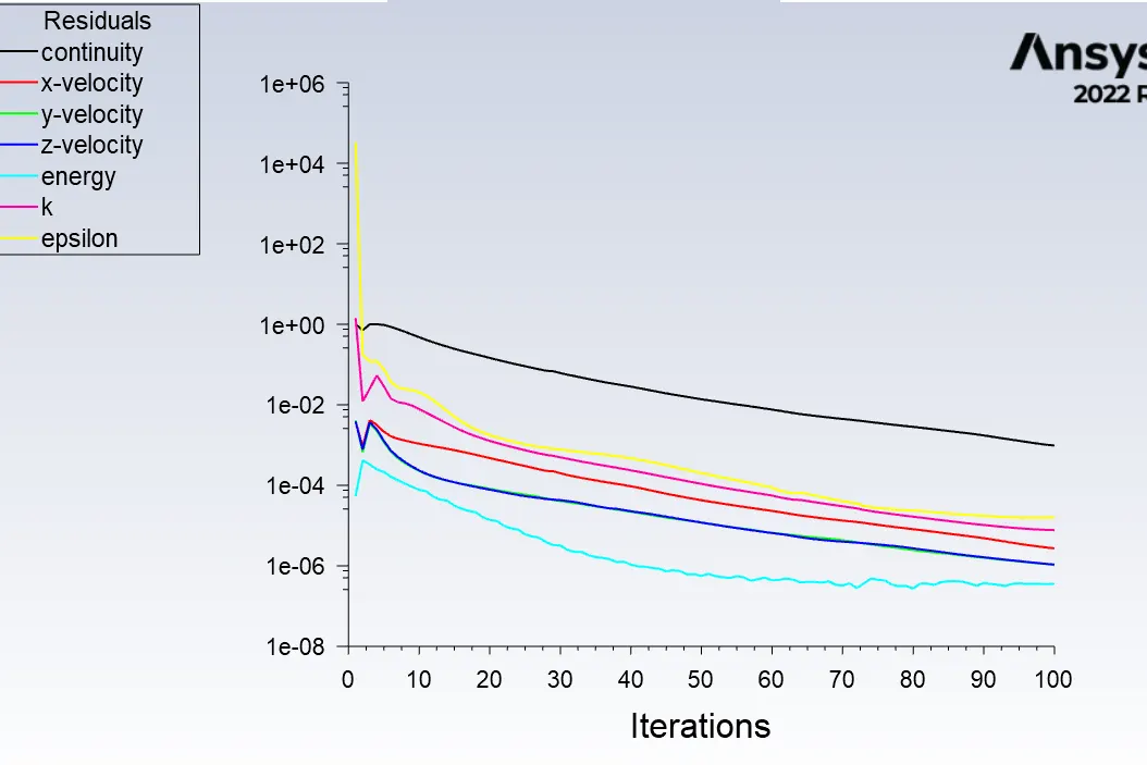
7. Solution is converged for 400 iterations
8. Area weighted temperature in processor
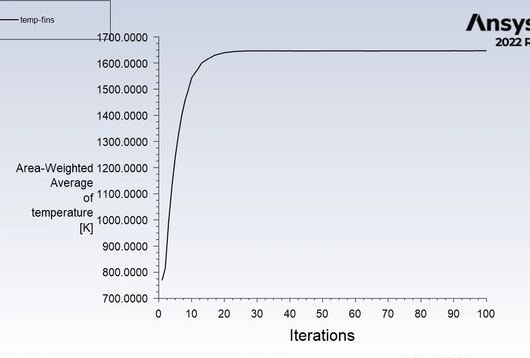
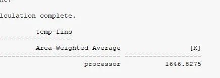
Eventhough solution is converged heat transfer coefficient is not calculated in this coarse mesh.
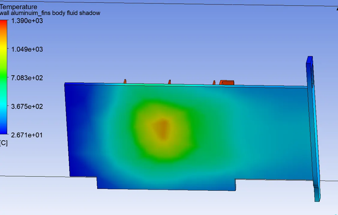
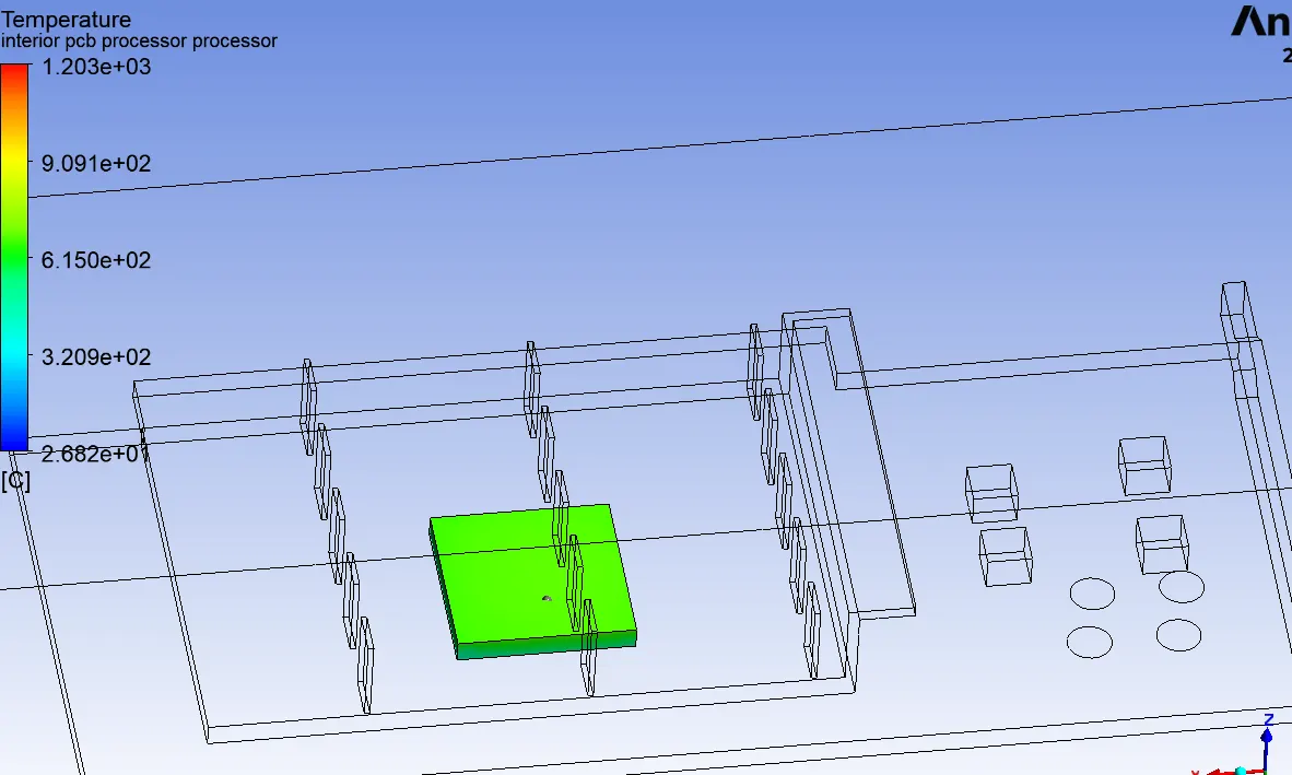
9. Temperature contour
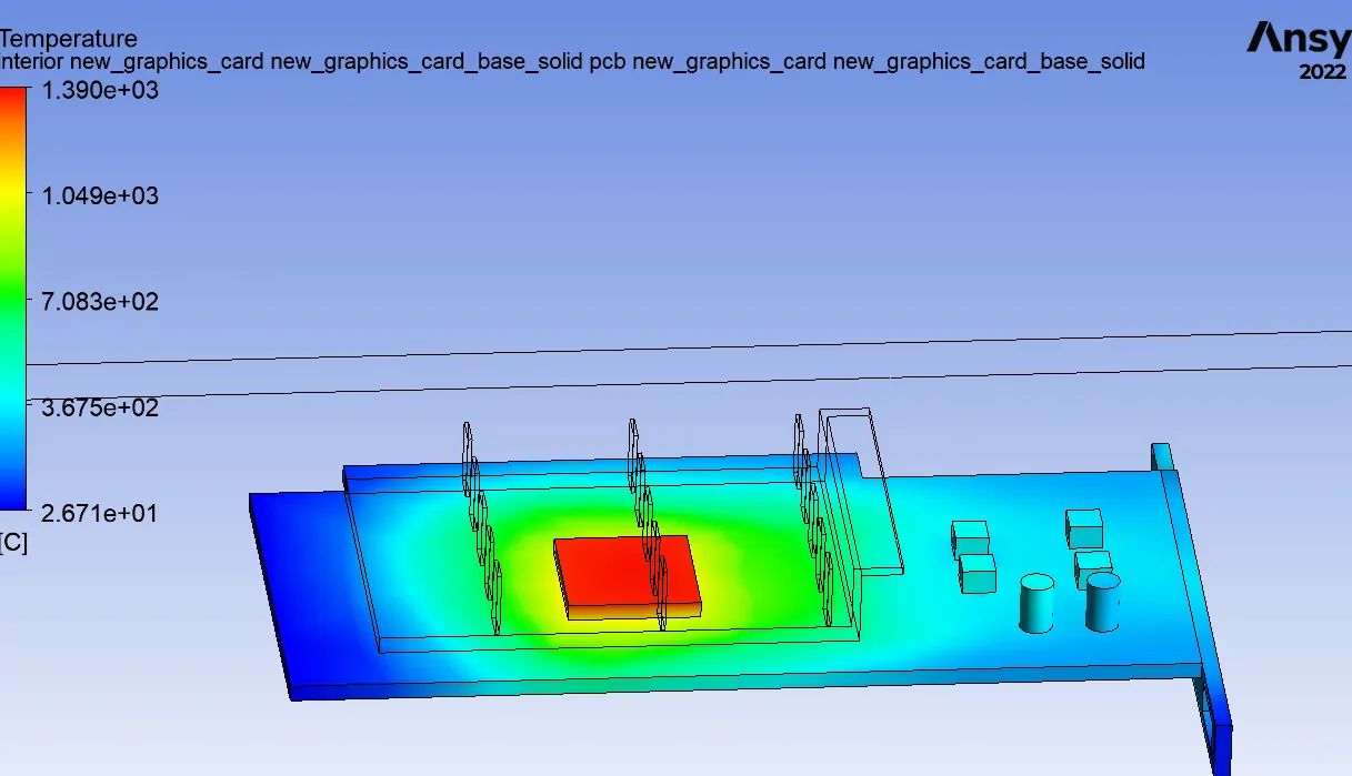
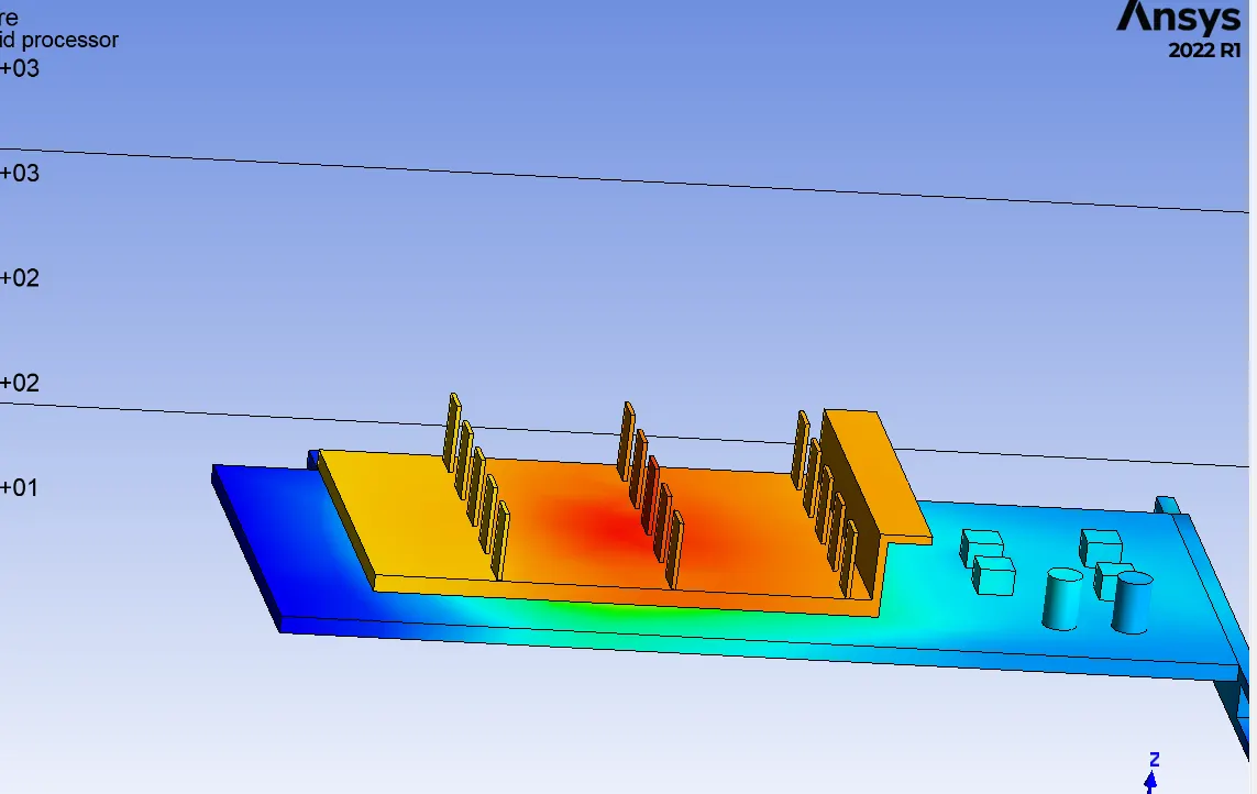
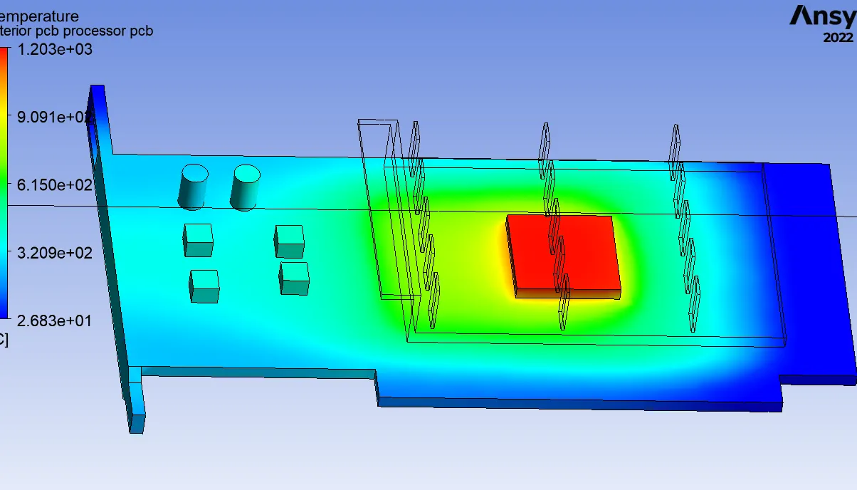
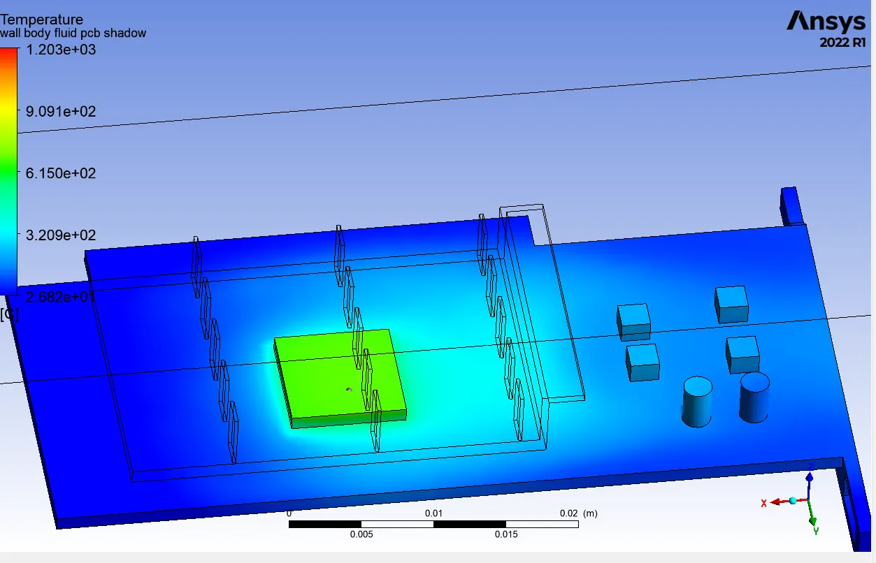
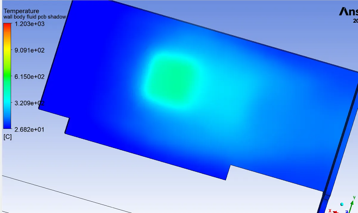
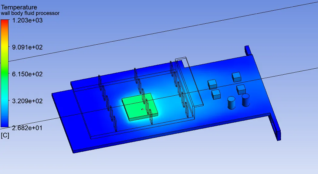
Since aluminium has more thermal conductivity, more heat is transfered to the fins and lower temperature is observed in bottom side of the processor
Refining mesh
- 0.2 mm mesh length is used in processor
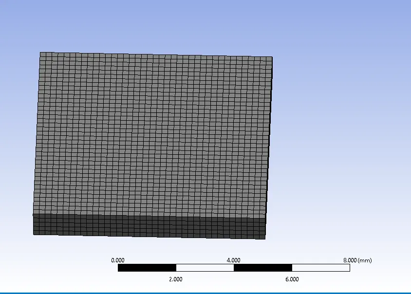
2. 1 mm used in fins
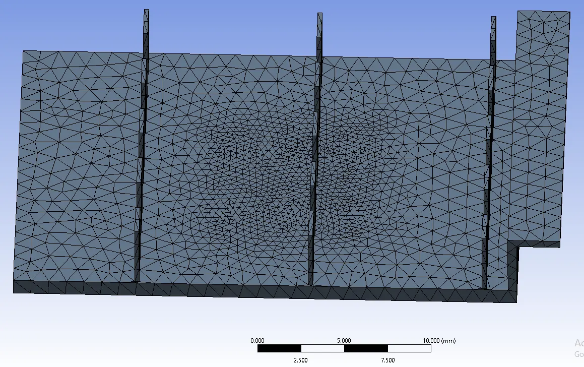
3.1.5 mm used in PCB
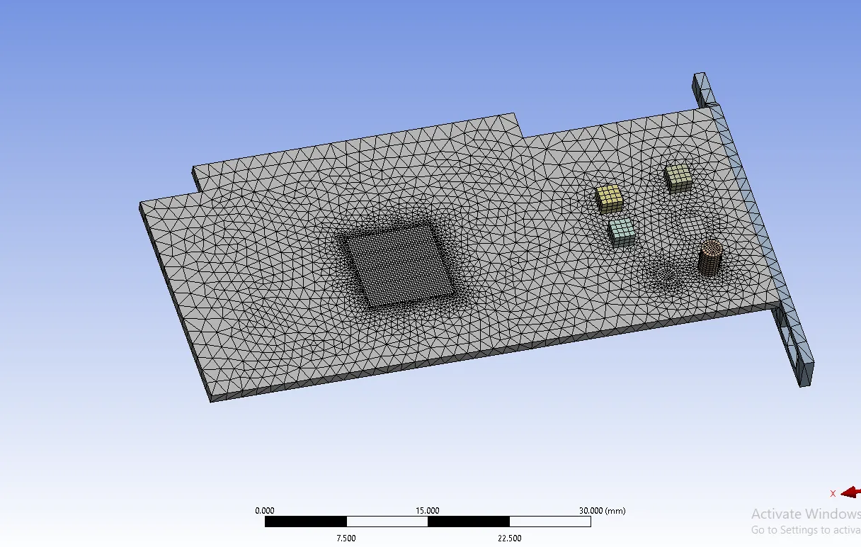
4. 0.5 mm used in enclosure
5. Total no of elements and nodes

Case 2 - Refined mesh - velocity 1 m/s
1. solution is converged
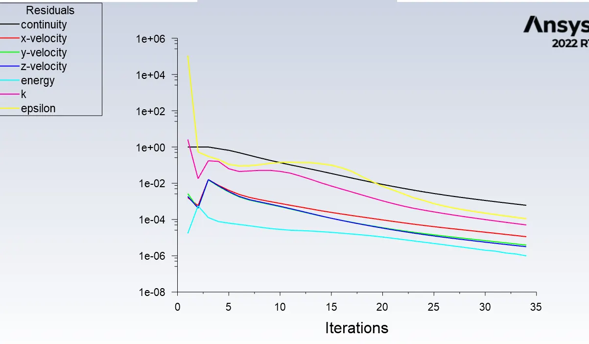
2. Temperature in processor
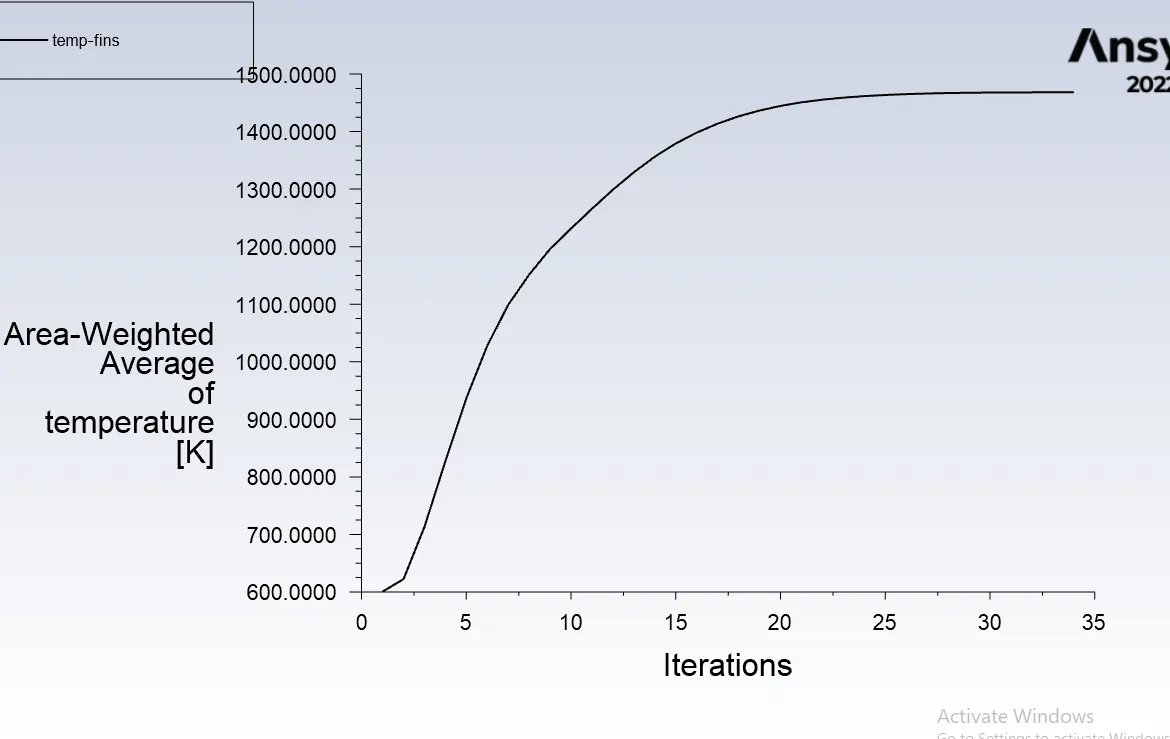
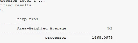
3. Temperature plot
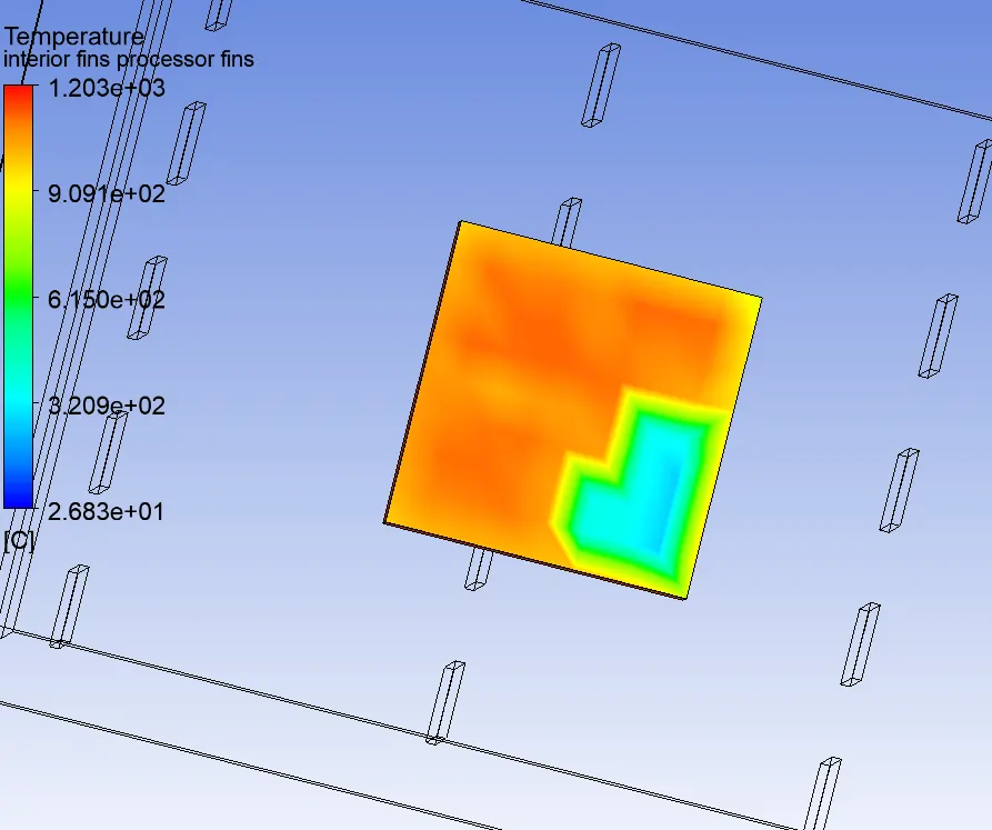
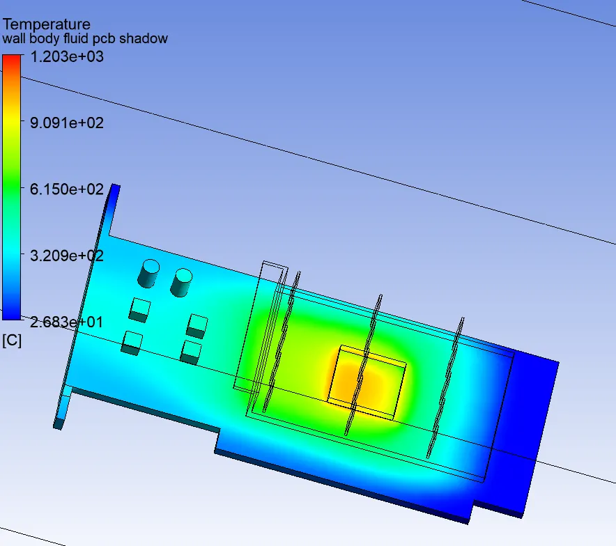
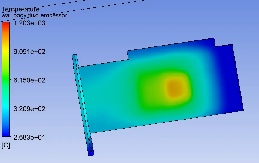
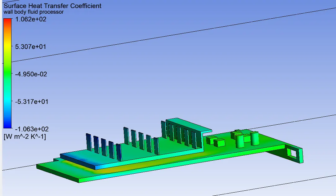
Heat transfer coefficient
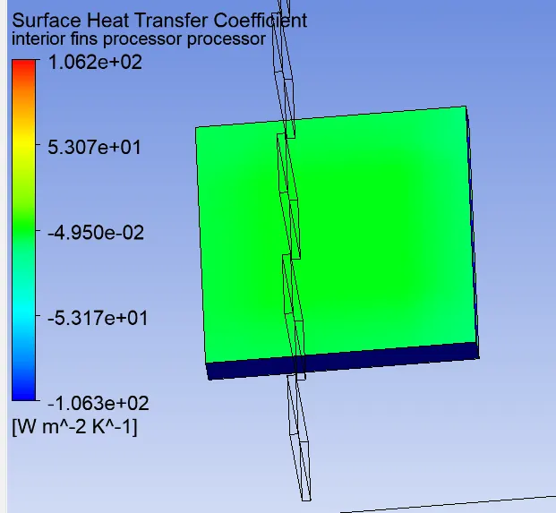
Surface heat transfer coefficient in processor is 5.3 W/mk
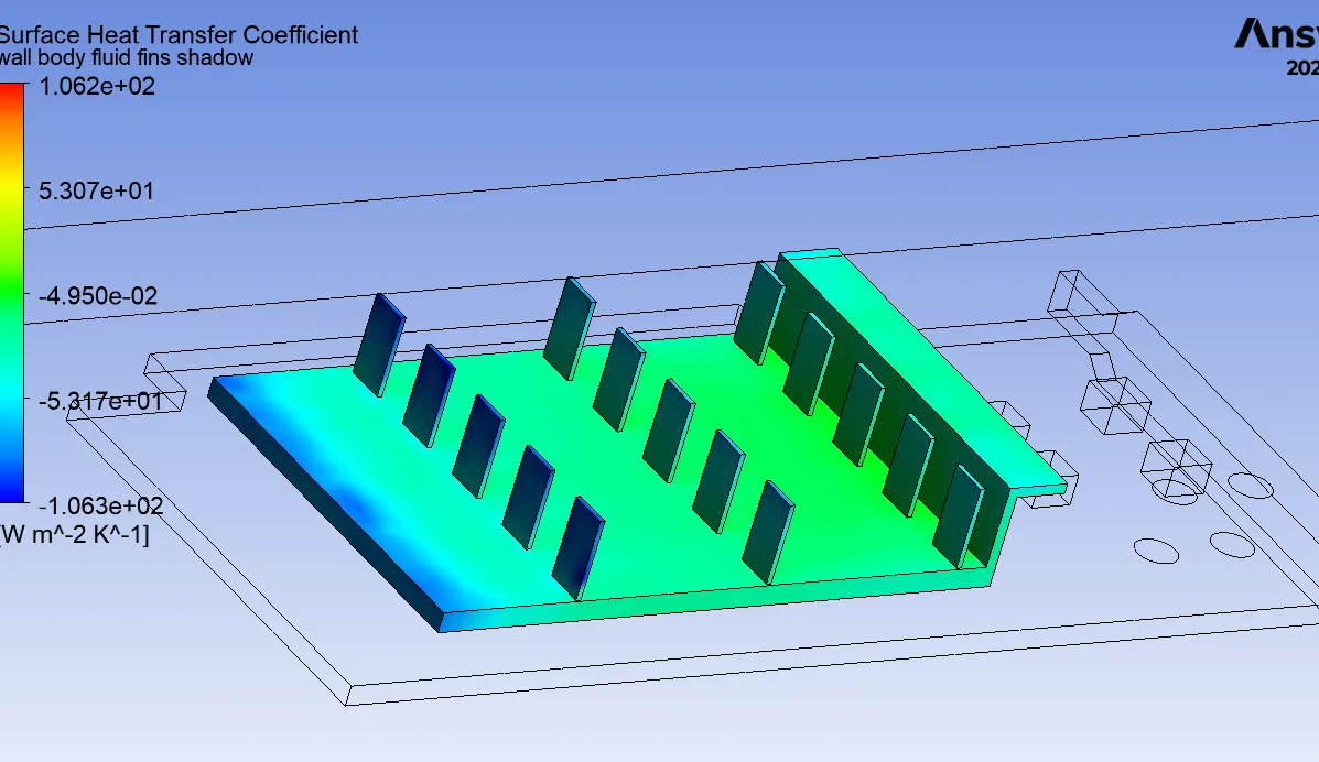
In fin region region heat transfer coefficient is increased along the length
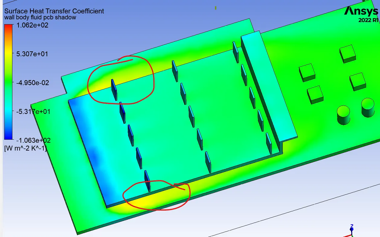
In PCB more heat transfer coefficient adjacent to the fin
Case 3 refined mesh velocity = 3 m/s

Temperature in processor
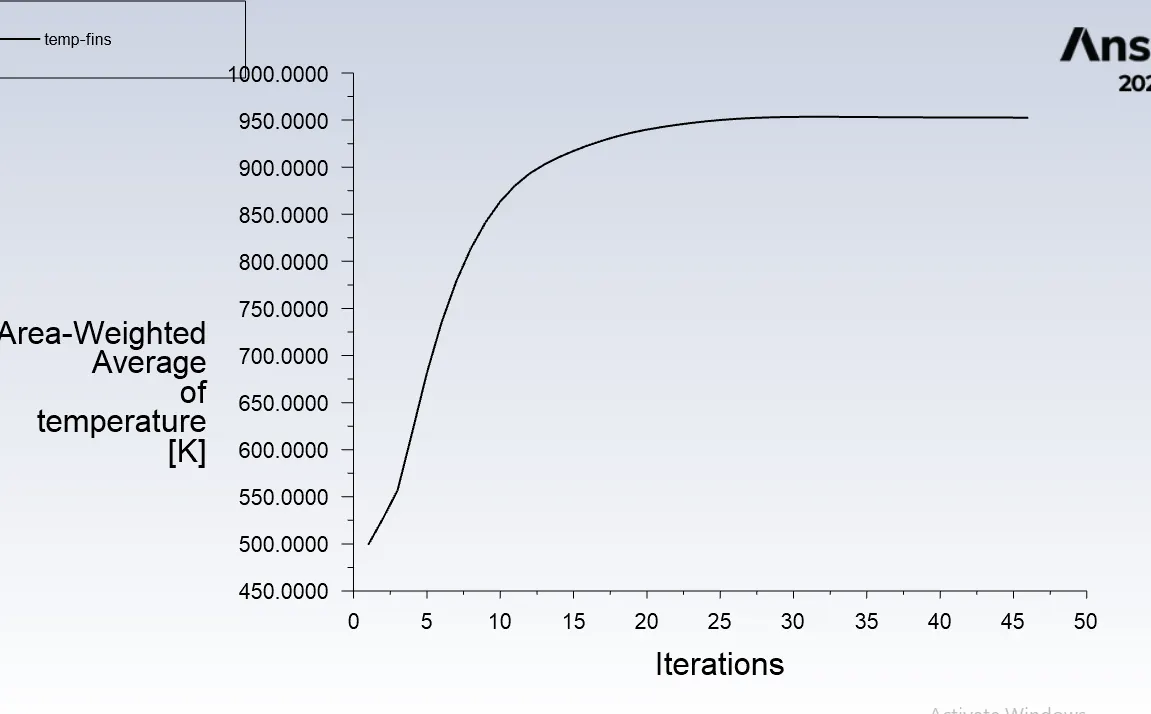
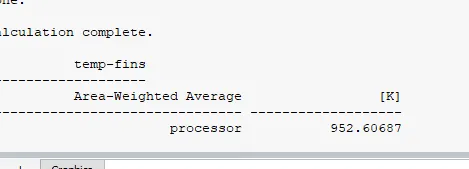
As the velocity increases to 3 m/s temperature decreased to 952 K
Temperature contour
Surface heat transfer coefficient
Case 4 refined mesh velocity = 5 m/s
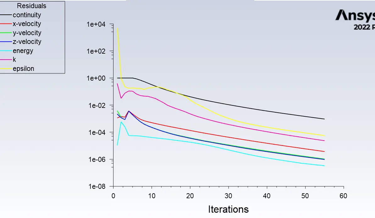
solution is converged
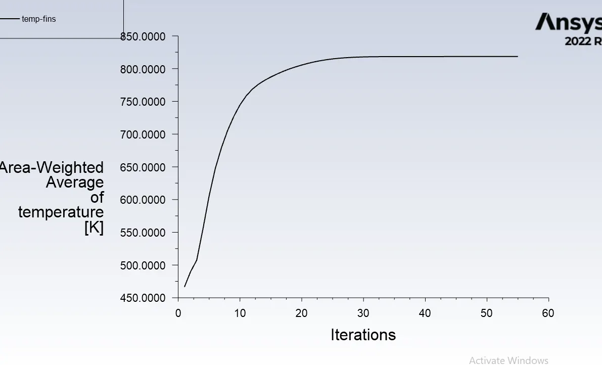
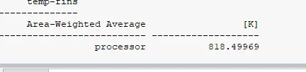
Temperature in processor
Temperature contour
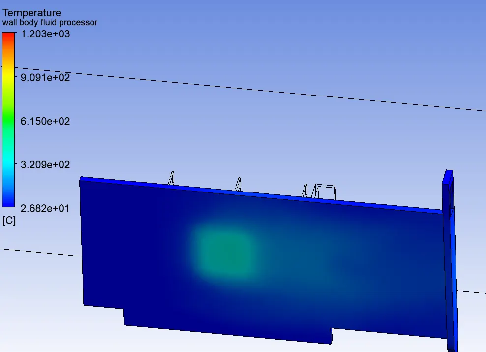
Back side of PCB
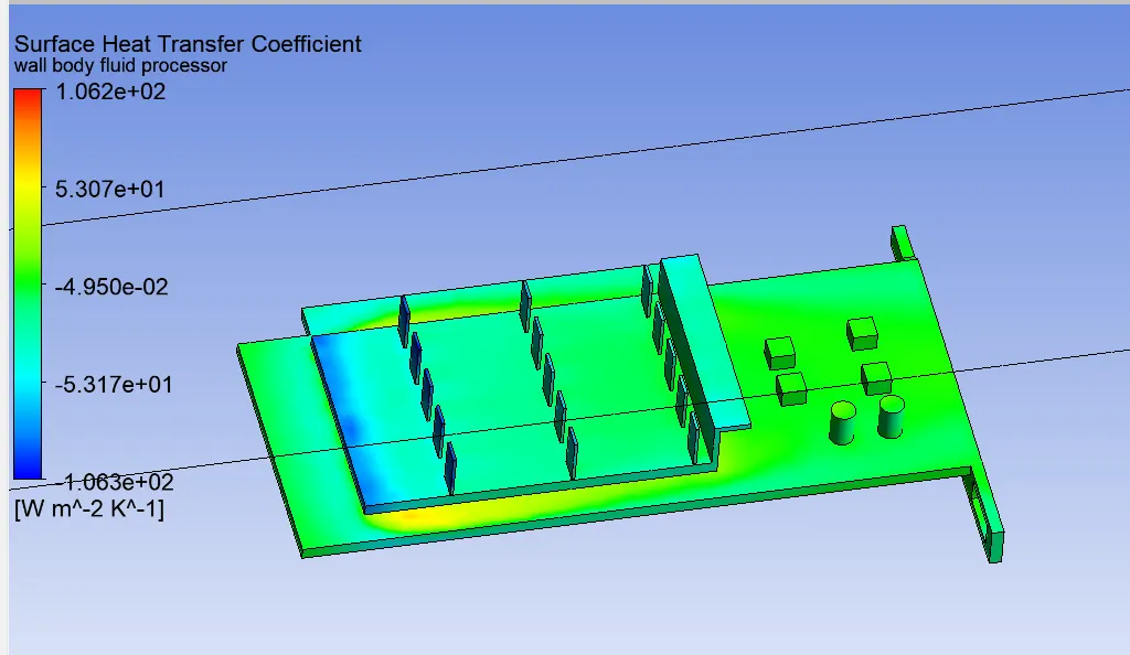
Surface heat transfer coefficient:
Conclusion:
| Case | Velocity(m/s) | no of elements | Temp (K) | HTC W/mk |
| Case 1 | 1 | 81394 | 1646 | |
| Case 2 | 1 | 1431860 | 1498 | 5.3 |
| Case 3 | 3 | 1431860 | 952.6 | |
| Case 4 | 5 | 1431860 | 818 |
It is evident from the above table the temperature in the proccessor is decreased as the velocity of the inlet air increases
Fins in the first row experiencing less heat transfer when compared to the other rows.
Number of iteration for converging the results decreased with increase the number of elements
The property of the materials plays a vital role in surface heat transfer coefficient.
References:
<!-- [if !supportLists]-->1. <!--[endif]-->http://www.designlife-cycle.com/nvidia-gpu
<!-- [if !supportLists]-->2. <!--[endif]-->https://www.efunda.com/materials/elements/TC_Table.cfm?Element_ID=Si
<!-- [if !supportLists]-->3. <!--[endif]-->https://www.nuclear-power.com/silicon-specific-heat-latent-heat-vaporization-fusion/#:~:text=Specific heat of Silicon is,Silicon is 384.22 kJ/mol.
<!-- [if !supportLists]-->4. <!--[endif]-->https://materials.gelsonluz.com/2019/08/density-of-silicon-si-gcm3-kgm3-uses.html
<!-- [if !supportLists]-->5. <!--[endif]-->https://www.nature.com/articles/s41598-020-71745-w#:~:text=Typically, epoxy resin is used,−1 K−11.
<!-- [if !supportLists]-->6. <!--[endif]-->https://www.engineeringtoolbox.com/specific-heat-polymers-d_1862.html
<!-- [if !supportLists]-->7. <!--[endif]-->https://www.sciencedirect.com/topics/engineering/epoxy-material#:~:text=The density of epoxy resin,; Mallick., 2007).