Conjugate Heat Transfer Analysis on a Graphics card using ANSYS Fluent
Week 6 Report.
- Aim: To perform a Conjugate Heat Transfer simulation for a Graphics card and understand the temperature distribution as the processor a heat source.
- Theoretical Introduction:
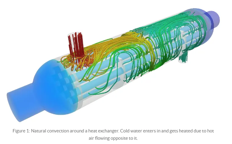
Conjucate heat transfer (CHT):The conjugate heat transfer analysis was introduced after the computers came into wide use. Before this, the empirical relation of proportionality of heat flux to temperature difference with heat transfer coefficient was the only tool in theoretical heat convection since the times of Newton. This model, based on a strictly mathematically stated problem, describes the heat transfer between a body and a fluid flowing over or inside it as a result of the interaction of two objects. The physical process and the governing equations are considered for the two separate sub-domains. Matching conditions for these solutions at the interface provide the distributions of temperature and heat flux along the body–flow interface, eliminating the need for a heat transfer coefficient. Moreover, it may be calculated using these data.
The CHT analytical method is used for various applications such as Electronic cooling, Boilers, Heat exchangers, Engine cooling systems, etc.
Cooling systems in Graphics card:
Computer cooling is required to reduced waste heat produced by the computer components to keep them within the operating limits. Exceeding the operating limits would cause temporary or permanent damage to the components. so it is necessary that the component should be within the permissible limits. Components that are susceptible to temporary malfunction or permanent failure if overheated include integrated circuits such as CPUs, chipsets, graphics cards, and hard disks.
The use of heatsinks cooled by airflow reduces the temperature rise produced by a given amount of heat. Attention to patterns of airflow can prevent the development of hotspots. Computer fans are widely used along with heatsink fans to reduce the temperature by actively exhausting hot air. There are also more exotic cooling techniques, such as liquid cooling. All modern-day processors are designed to cut out or reduce their voltage or clock speed if the internal temperature of the processor exceeds a specified limit.
- Procedure:
First, we are going to open the workbench and going to click on Fluid Flow(Fluent). It is going to open the module in the Project Schematic.
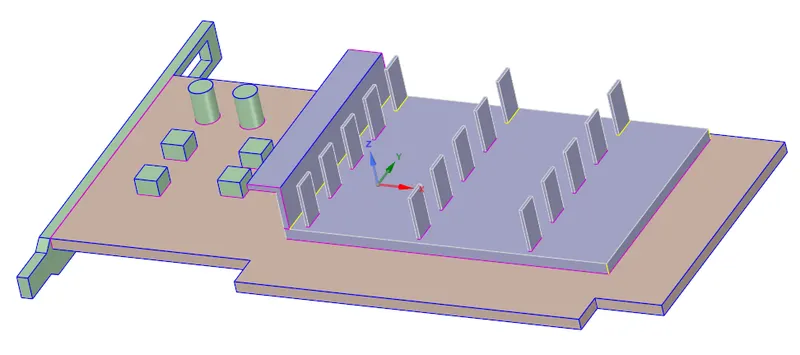
2. Now we are going to click on the geometry. It will take you to the SpaceClaim. So now we can see the original design on which we are going to do our simulation.
3. We want the mesh to be finer in the plates of the fins as compared to the base of the fins. So we are going to split the fins into two components. One is fins-base and the second one is fins-plates. So in order to that, we are going to use the split body command and we are going to create two components.
4. Now we want that information should flow into all body parts of the processor so we are going to select the share option in the workbench.
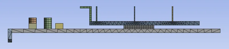
5. Now we are going to open the mesh. Here first we are going to insert the mesh and we are going to give the enclosure mesh to be hexagonal and we are going to give the element size to be 15 mm.
6. Next we are going to give the body size to every part of the graphic card. So we are going to insert the sizing for every body part. We are going to give the following mesh element size:-
We are going to give a 3mm element size to be the base of the graphic cards.
We are going to give a 0.5mm element size to be the processor. The processor is our source of energy that's why we are going to give the fine mesh to the processor.
We are going to give a 1.5mm element size to the base of the fins. The work of the fins is to keep the processor cool so the fins should be fine.
Now we are going to give a 0.22mm element size to the plates of the fins. Plates are very thin and the heat is going to the atmosphere from the plates. So it will be better if we make the plates finer as compared to the base of the fins.
We have taken the element size to 0.5 mm to the capacitor. There is also some heat generation in the capacitor so we are going to make it finer as compared to the base of the graphic card.
And, now we are going to take the element size 2mm to the four blocks of the graphic cards.
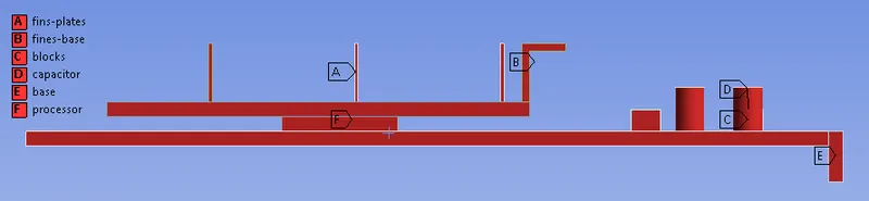
7. We are going to be naming the body parts.
8. Now we are going to update the mesh. Now we are going to set up the case. We are going to take the model to be the turbulent k-ω SST model.
9. In the Fluent we will go to Physics. Here we choose the type of solver, we have taken the pressure-based type solver.
10. Next we have to choose the velocity formulation here we have taken absolute velocity formulation. Now we are going to choose the time, we are using a steady time. We want to calculate the heat transfer coefficient so we are going to consider the energy equation also.
11. And next we are going to give the initial boundary condition. So at the inlet, we are going to give 2.5 m/s inlet velocity and at the outlet, we are going to give the pressure to be zero (static pressure).
12. Now we are going to select the material. We are taking air to be our fluid material and for the solid body, we are going to use different-different materials. We want the processor to be cooled. So we are going to take the material for the processor to be copper. Because copper is a good heat conductor so the heat transfer coefficient will be high for the copper. Because of that more heat will go into the atmosphere and the processor will become cooled.
In the graphic card, there are fins present on the processor. The work of the fins is to cool down the processor. So for the same reason, we are going to use copper material for the fins.
For the other parts, we are going to use Aluminium material. Like in the base of the graphic card, Capacitor, and blocks. Because we don't want for heat to go to the base of the graphic card and Aluminium is a low conductor as compared to Copper.
13. The heat will generate from the processor. So we are going to make the processor be our heat source. In order to do that, we are going to go to the cell zone and where we are to click on the processor and we are going to edit it. Now we are going to enable the source box. Then we are going to take the power to be 128 Watt and the area of the processor is 64 `mm^3` So the energy we are going to take is 2e9 `W/(m^3)`
In the cell zone, we defined which type of material we are using in which body part of the Graphic card.
14. Next, we are going to initialize the simulation and we are going to create the temperature contour. After that, we are going to start the simulation.
- Results:
Residual
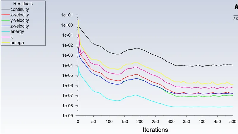
From the residual graph, we can see that after some time it is repeating the pattern so we can say that we get the result gets converge.
Temperature
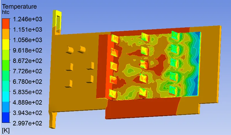
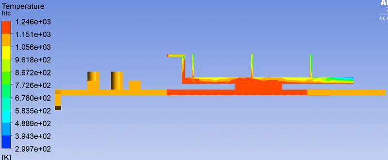
We are getting a maximum temperature of 1246K on the graphic card.
We can see from the above pictures that the maximum temperature we are getting at the base below the processor and wall at the end of the fins base. The temperature is high at the base of the processor because the heat is going directly from the processor to the base of the graphic card and it has less heat transfer to the atmosphere.
The wall at the end of the fin base has a high temperature because when the air passes from the fins plates and above the fins base, the temperature of the air increases. So when it hits the wall, the wall absorbs that heat, and temperature increases.
.
Heat Transfer Coefficient
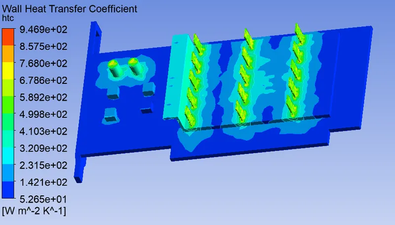
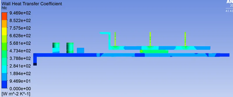
We are getting a maximum heat transfer coefficient of 946.9 `W/(m^2 k)`.
We are getting maximum heat transfer at the fins plate and at the capacitor. The plates have a high heat transfer coefficient because the maximum heat generated in the processor goes to the fins so the heat will go to the maximum from the fins to the air by the fins.
Vector Plot
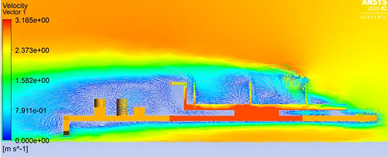
In the above picture, we can see the circulation of the air in the graphic card. The velocity of the air is very less in between the fins plates and after the fins.
Case-2
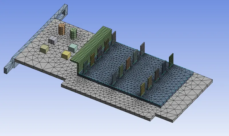
Coarse Mesh
In the coarse mesh these element sizes I have taken:-
Enclosure = 20 mm
Graphic Card base = 4 mm
Processor = 0.8 mm
Fin Base = 2 mm
Fin Plates = 0.3 mm
Capacitor = 0.8 mm
Blocks = 2.4 mm
Result
Residual
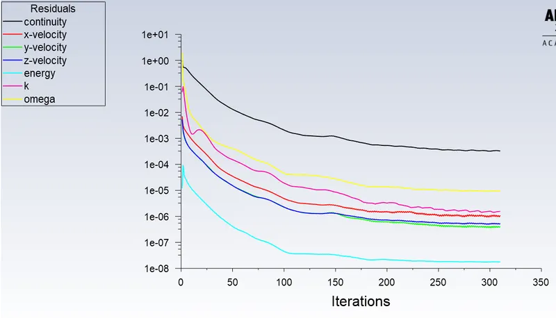
From the residual graph, we can see that after some time it is repeating the pattern so we can say that we get the result gets converge.
Temperature
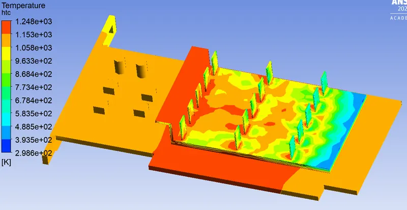
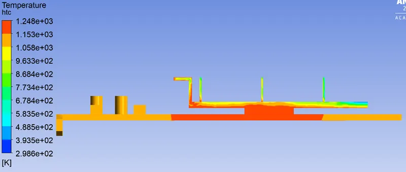
We are getting a maximum temperature of 1248K on the graphic card.
Heat Transfer Coefficient
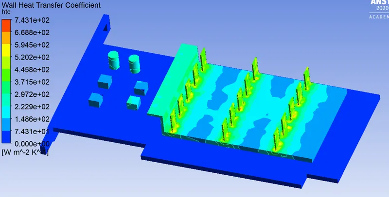
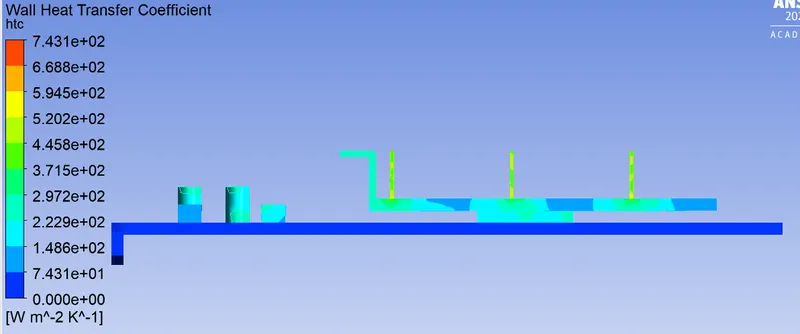
We are getting a maximum heat transfer coefficient of 743.1 `W/(m^2 k)`
Vector Plot
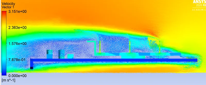
In the above picture, we can see the circulation of the air in the graphic card. The velocity of the air is very less in between the fins plates and after the fins.
Case-3
In this case, we are going to take the inlet velocity to be 1 m/s and we are going to simulate for the fine mesh as same as the case-1.
Result
Residual
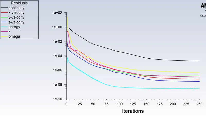
From the residual graph, we can see that after some time it is repeating the pattern so we can say that we get the result gets converge.
Temperature
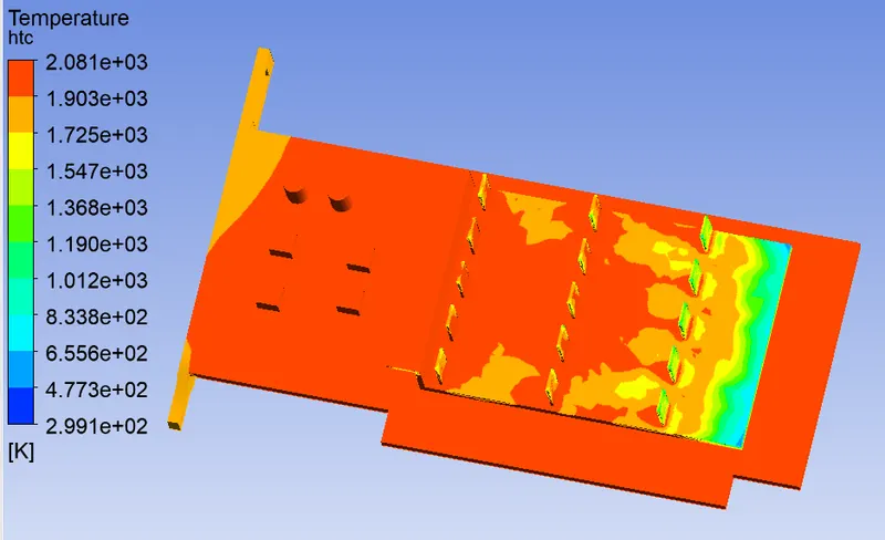
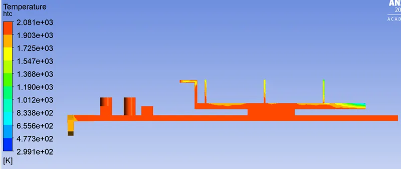
We are getting a maximum temperature of 2081k on the graphic card.
Heat Transfer Coefficient
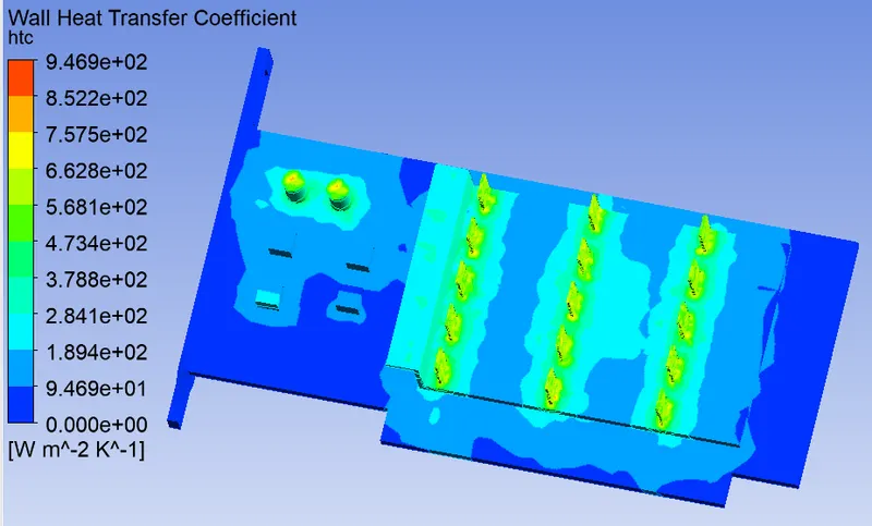
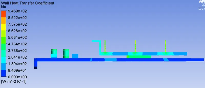
We are getting a maximum heat transfer coefficient of 946.9 `W/(m^2 k)`
Vector Plot
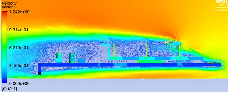
In the above picture, we can see the circulation of the air in the graphic card. The velocity of the air is very less in between the fins plates and after the fins.
Case-4
In this case, we are going to take the inlet velocity to be 5 m/s and we are going to simulate for the fine mesh as same as the case-1.
Result
Residual
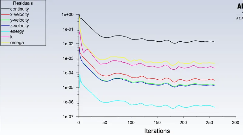
From the residual graph, we can see that after some time it is repeating the pattern so we can say that we get the result gets converge.
Temperature
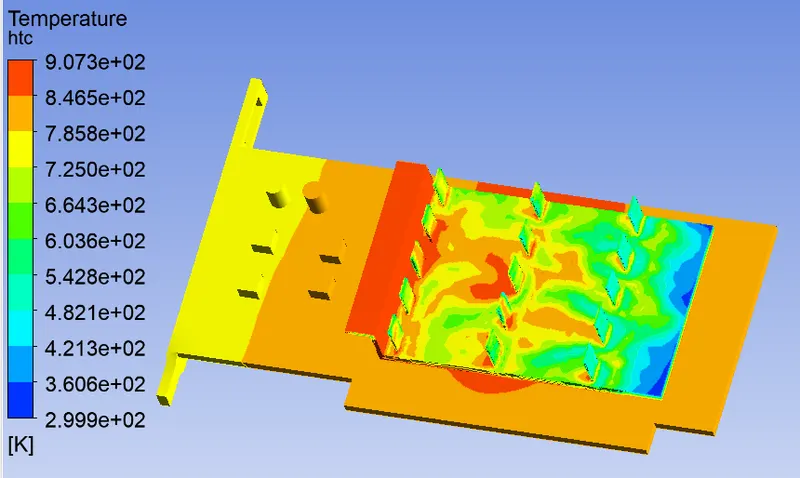
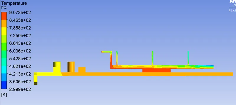
We are getting a maximum temperature of 907.3K on the graphic card.
Heat Transfer Coefficient
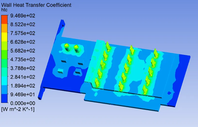
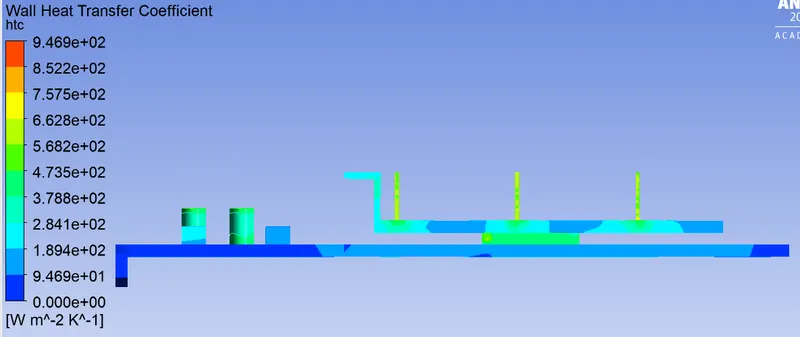
We are getting a maximum heat transfer coefficient of 946.9`W/(m^2 k)`.
Vector Plot
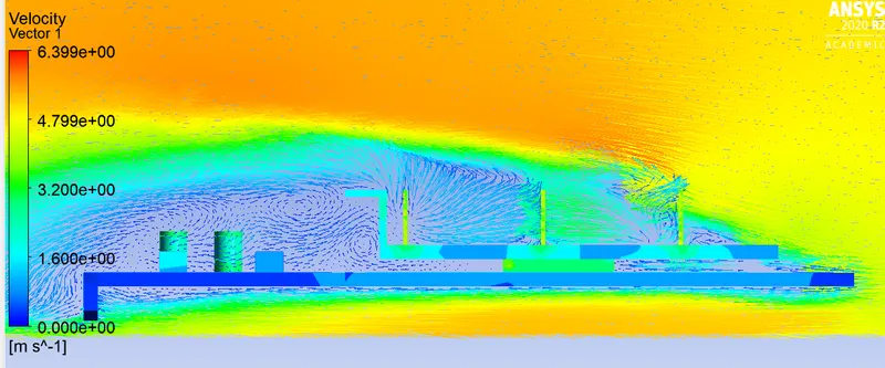
In the above picture, we can see the circulation of the air in the graphic card. The velocity of the air is very less in between the fins plates and after the fins.
Comparision
Velocity (m/s) Maximum Temperature (K) Maximum Heat Transfer Coefficient (`W/(m^3 k)`) 1 2081 946.9 3.0 1246 946.9 5 907.3 946.9 From the table, we can see that with the increase of the velocity of the air the temperature value decreases but we got the heat transfer coefficient value the same. Because the velocity value doesn't change that much.
- Conclusions:
When we increase the velocity the temperature of the graphic card decreases. Because the air is taking heat from the graphic card and convection is occurring.
The maximum temperature we are getting at the base below the processor and wall at the end of the fins base. The temperature is high at the base of the processor because the heat is going directly from the processor to the base of the graphic card and it has less heat transfer to the atmosphere.
We are getting maximum heat transfer at the fins plate and at the capacitor. The plates have a high heat transfer coefficient because the maximum heat generated in the processor goes to the fins so the heat will go to the maximum from the fins to the air by the fins.