CHT Analysis on a Graphics card
Aim – To perform Steady-State Conjugate Heat Transfer (CHT) Simulation on Graphics Card
Objective –
- Run the simulation by varying the velocity from 1m/sec to 5m/sec for at least 3 velocities and discuss the results.
- Find out the maximum temperature and heat transfer coefficient attained by the processor.
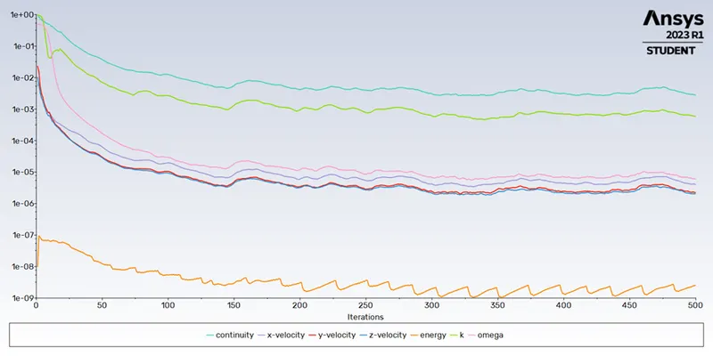
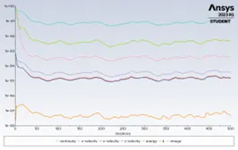
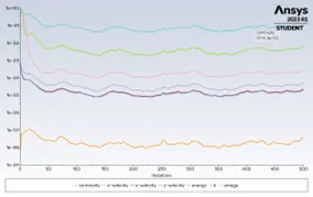
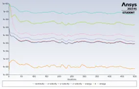
- Prove that the simulation has achieved convergence with appropriate images and plots.
- Identify potential hotspots on the model.
Theory –
- Conjugate Heat Transfer (CHT) :
Conjugate heat transfer is the transport of heat by the interchange of thermal energy between two domains. The temperature of a system determines the amount of thermal energy it has available, and the heat flux through its outside walls determines how much thermal energy is moving through the system. Heat is transferred through conduction through solid surfaces, convection through walls, and convection through liquids.
With the help of CHT, we can properly forecast the temperature as well as the hotspot regions at the solid-fluid interface, such as conduction through solids, convection through fluid, and thermal radiation. Additionally, it gives the fluid's motion inside the solid's solid's velocity and pressure distribution. Additionally, CHT can be used in design optimisation to increase cooling and heat transfer efficiency.
- Graphics Card :
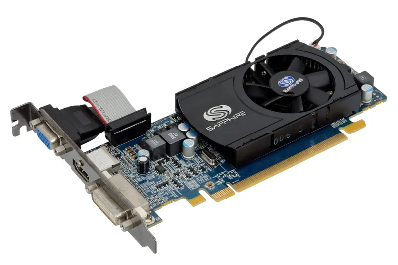
A video card is an extension card that produces a feed of output images for a display device (such as a computer monitor). It is also known as a graphics card, display card, graphics adapter, or display adapter. The majority of video cards don't have a 6-inch basic output limit. Their built-in graphics processor can do additional work, freeing up the computer's primary processor to do something else.
Geometry Setup -
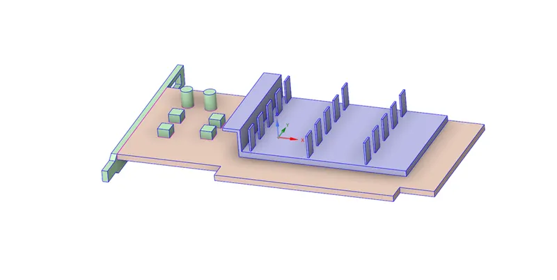
- Edit the geometry of the downloaded model of the graphics card inside the enclosure using SpaceClaim.
- Click on share prep to see any interference-causing edges so that various components can be meshed in a conformal manner.
- Share topology between the various components needs to be enabled so that relevant data may be shared across various mesh zones.
Mesh Setup –
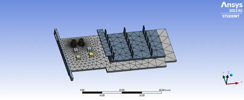
- Let's name the various parts of the graphic card before creating a base mesh so that it will be simpler to locate them during fluent setup.
- The simulation will be aided by our basic naming choices of base, processor, and fins.
- To create a base mesh, click generate mesh; the 3 solid components' bodies can then be sized.
- After generating the body sizing for the three components, construct the mesh since it is a basis mesh with more than 1 lac elements that aids in precise solution-finding.
- Exit Mesh setup to simulate in fluent after constructing the mesh.
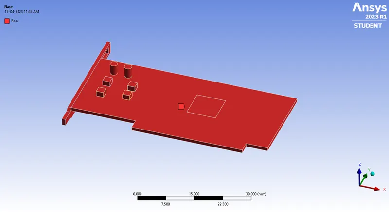
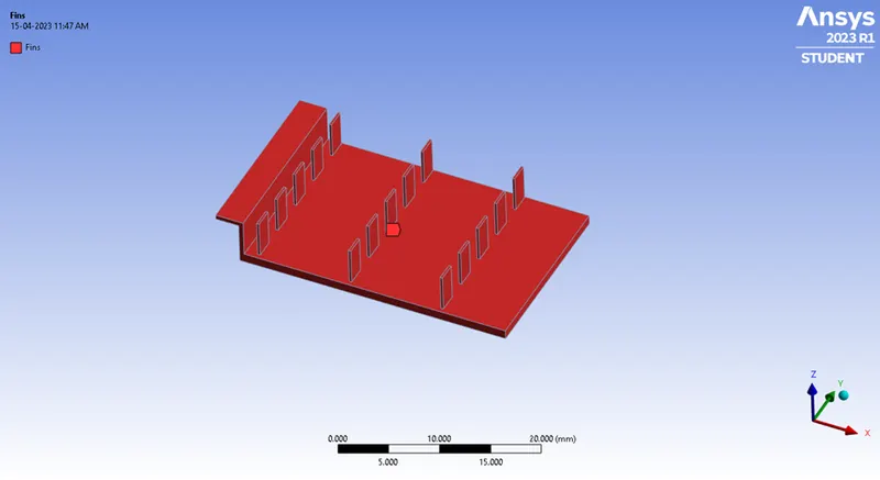
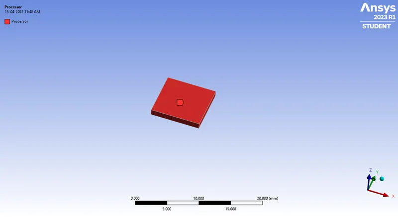
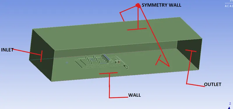
- Base Line Mesh –
- Element Order : Linear
- Element Size : Default
- of Nodes : 15681
- of Elements : 83585
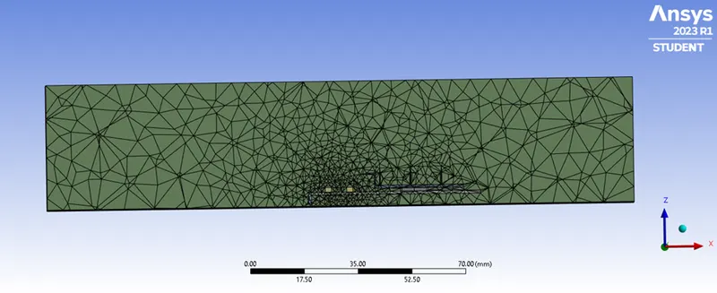
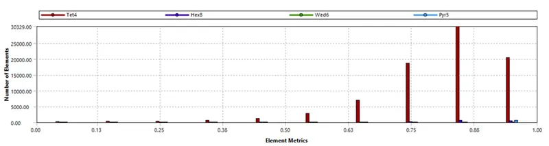
We have some elements with quality less than 10%
Simulation Setup –
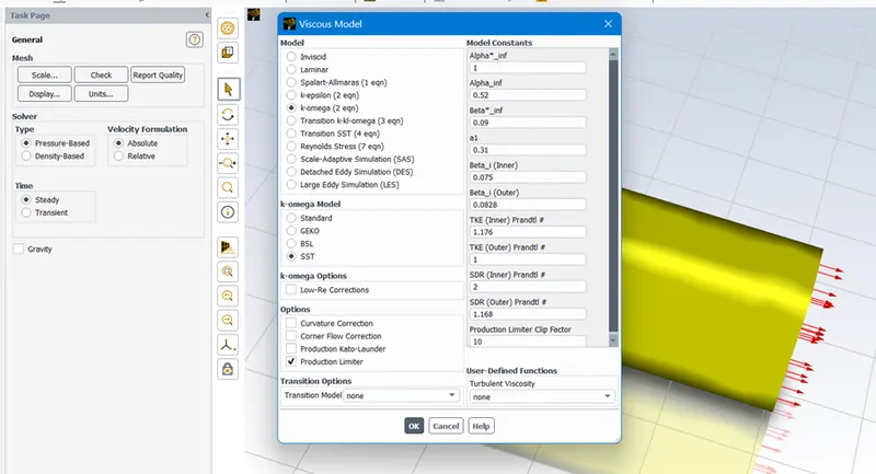
1.Solver: Steady
2.Type: Pressure Based
3.Turbulence Model: k-Omega(SST)
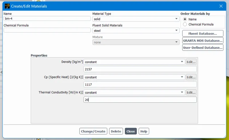
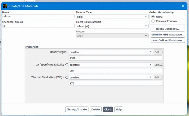
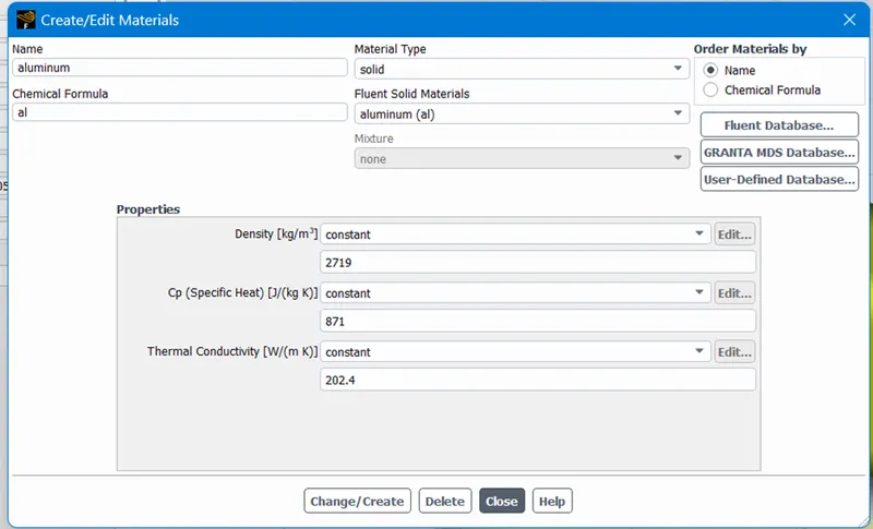
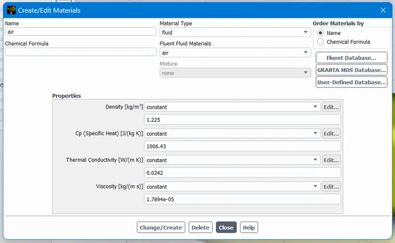
4.Materials: Different materials are used for each part, some of which are custom created
|
Part |
Material |
|
Base |
BM-4 (Custom) |
|
Fin |
Aluminium |
|
Processor |
Silicon (Custom) |
|
Enclosure |
Air |
Boundaries –
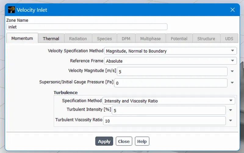
- Inlet :
- Velocity – 5m/s
- Temperature – 300 K
- Outlet :
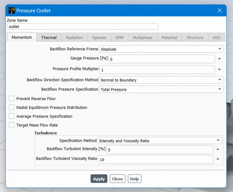
- Type : Pressure Outlet
- Pressure : 0 Pa (Gauge Pressure)
- Temperature – 300 K
Cell Zone Conditions –
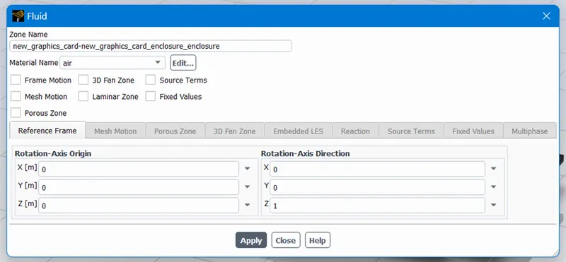
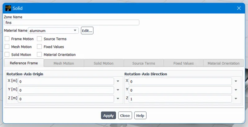
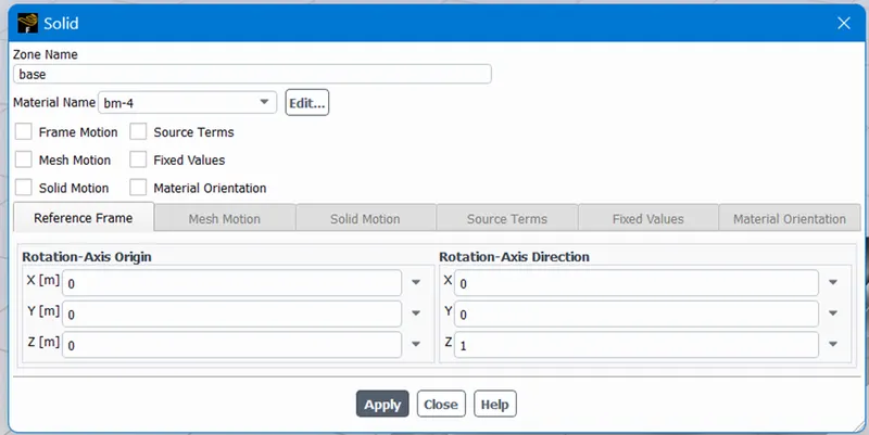
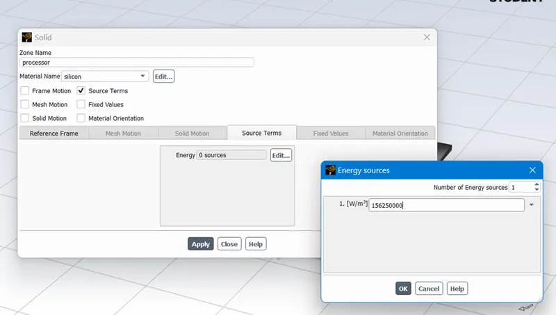
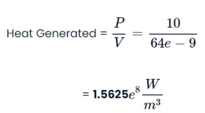
It is assumed that the processor is the only source of heat. The processor's heat output is computed as follows:
Graphics Card Power = 10W
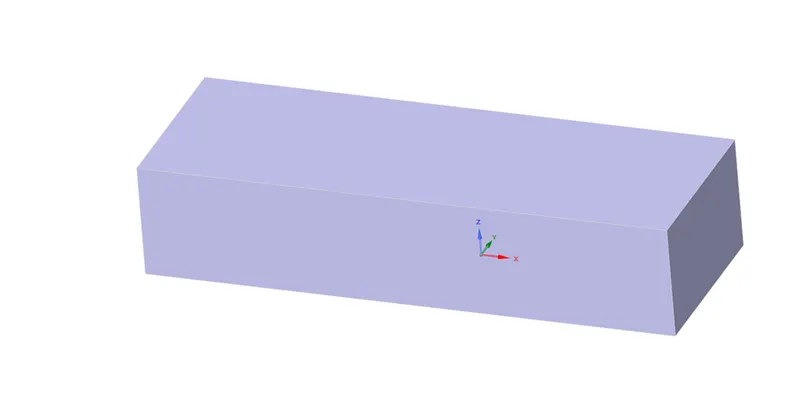
Volume of the card = 8 x 8 x 1

Solution –
- Method: Standard
- Number of Iterations: 500
Simulation Output :
- Iterations
Post Processing –
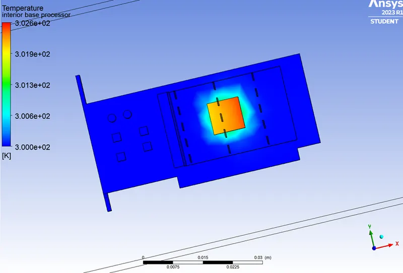
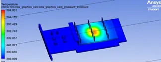
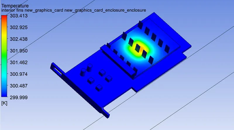
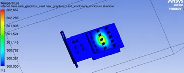
- Global Hotspot Region
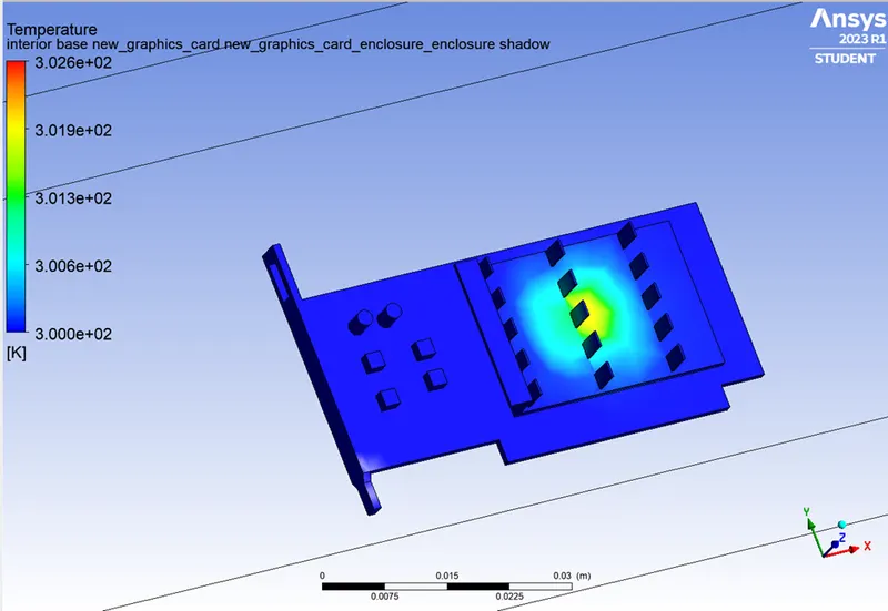
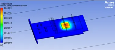
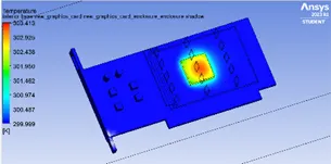
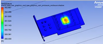
- Hotspot Around the Processor
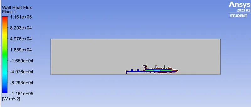
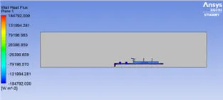
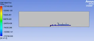
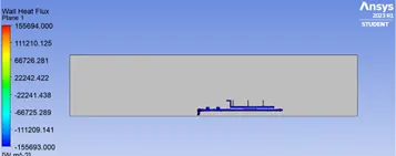
- Wall Heat Transfer Coefficient
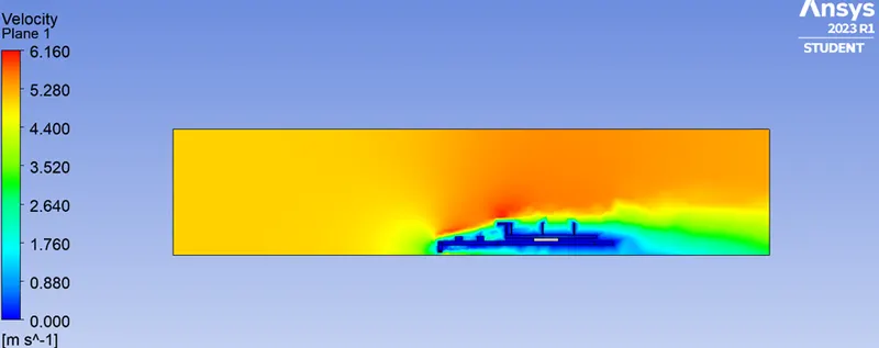
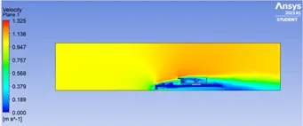
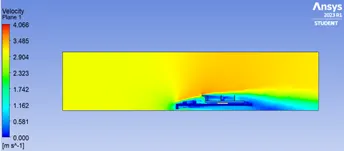
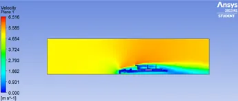
- Velocity Contours
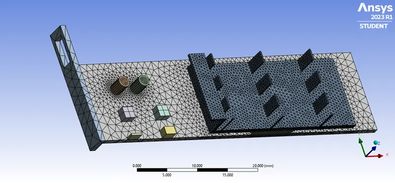
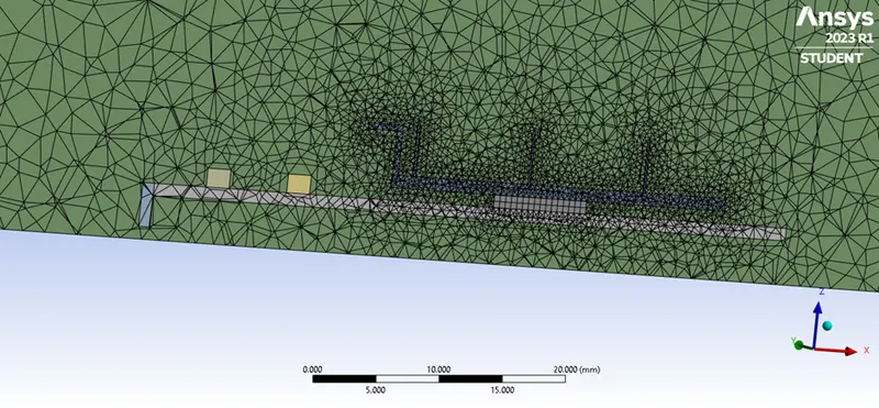
Refined Mesh –
1. Element Order: Linear
2. Element size: 0.003 m
3. Body Sizing (Fin)
Element Size: 0.0005 m
Curvature Capture: Yes
4. Body Sizing (Processor)
Element Size: 0.0005 m
Curvature Capture: Yes
5. Body Sizing (Base)
Element Size: 0.003 m
Curvature Capture: Yes
6. Number of Nodes: 77030
7. Number of Elements: 432557
Simulation Setup –
The simulation configuration was chosen using the same criteria as the initial mesh. The change in the inlet velocities will only affect the simulation's output.
Simulation Output –
- Iterations
|
Residuals |
Velocity 1 m/s |
Velocity 3 m/s |
Velocity 5 m/s |
 |
 |
 |
- Post Processing
|
Velocity 1 m/s |
Velocity 3 m/s |
Velocity 5 m/s |
|
|
Global Hotspot Region |
 |
 |
 |
|
Hotspot around the Processor |
 |
 |
 |
|
Wall Heat Transfer Coeff. |
 |
 |
 |
|
Velocity Contour |
 |
 |
 |
Results –
|
Velocity |
Temp. @ Processor [K] |
Temp. @ Fins [K] |
HTC @ Fins [K] |
|
1 m/s |
357.86 |
350.69 |
274.96 |
|
3 m/s |
332.42 |
326.23 |
277.31 |
|
5 m/s |
303.12 |
301.24 |
281.54 |
Conclusion –
- As the number of elements rises, precise temperature distribution data are achieved.
- It is clear from the prior to data that as inlet velocity increases, the net temperature of graphics card components falls.
- As a result, it can be concluded that a higher inlet velocity leads to better cooling and a lower average temperature, protecting the components from harm.
- Furthermore, it is evident that components' temperatures rise as inflow velocity drops from 5 m/s to 1 m/s, further demonstrating that higher velocity improves cooling.