Week 6 - CHT Analysis on a Graphics card
WEEK 6 – CHT ANALYSIS ON A GRAPHICS CARD
OBJECTIVES:
- Perform a steady-state conjugated heat transfer analysis on a model of a graphics card.
- Select the appropriate materials for the simulation.
- Mesh the geometry with a desirable combination and Explain the mesh setting used on this model.
- Simulate by varying the velocity from 1m/s to 5m/s for at least 3 velocities and discuss the results.
- Find out the maximum temperature and heat transfer coefficient attained by the processor.
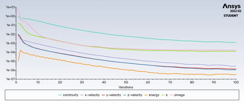
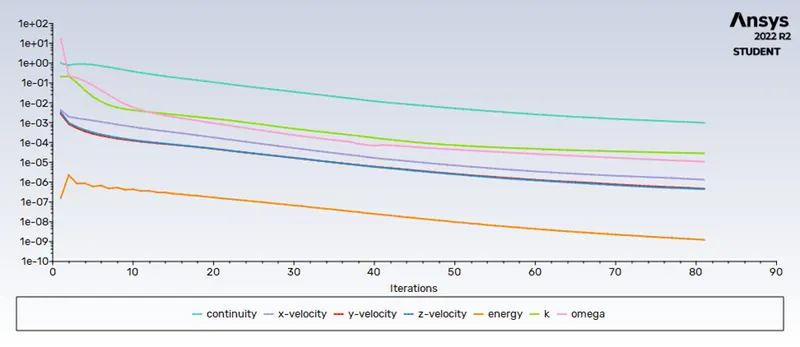
- Prove that the simulation has achieved convergence with appropriate images and plots.
- Identify potential hot spots on the model.
THEORY:
Conjugate Heat Transfer (CHT):
- It allows for the simulation of heat transfer between solid and fluid domains by exchanging thermal energy at the interfaces between them.
- CHT provides temperature prediction and also the hotspot regions at the solid-fluid interface.
- The CHT simulation predicts heat transfers like Conduction through solids, convection through fluid, and thermal radiation accurately.
- The physics of conjugated heat transfer is common in many engineering applications, including heat exchangers, HVAC, and electronic components design.
Graphic card:
- It is an integrated circuit that generates the video signal sent to a computer display. It is also called a video card.
- The graphic card is usually located on the computer motherboard or is a separate circuit board but is sometimes built into the computer display unit.
- Here, we take a 3d model of a simple graphic card that consists of a processor, fins, and a base.
SIMULATION PROCEDURES:
- ANSYS- Workbench is used.
a) BASELINE MESH (velocity = 1 m/s):
Geometry - SpaceClaim:
- The graphic card.STEP file is imported to SpaceClaim.
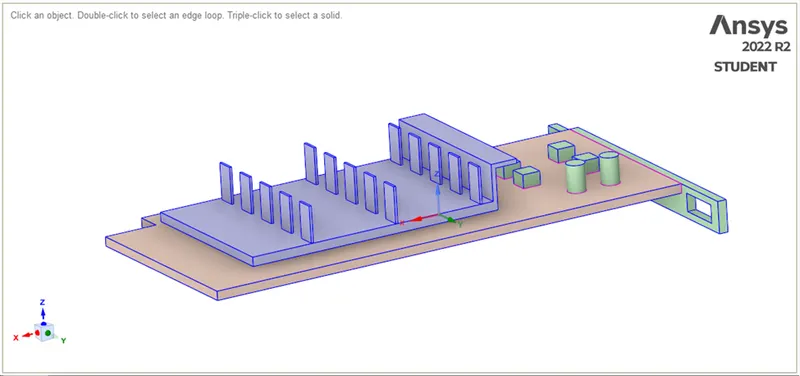
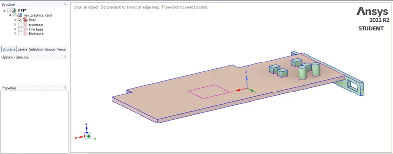
- The base of the graphic card is shown below,
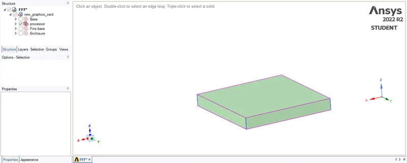
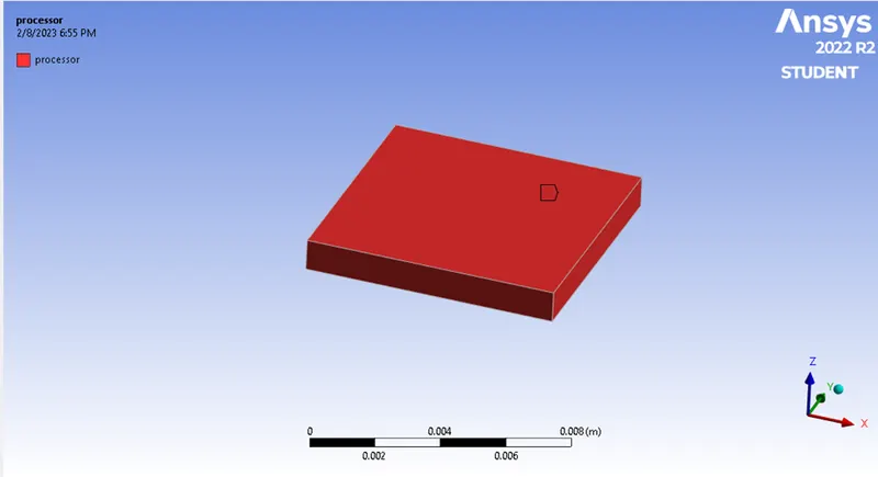
- The processor of the graphic card is shown below,
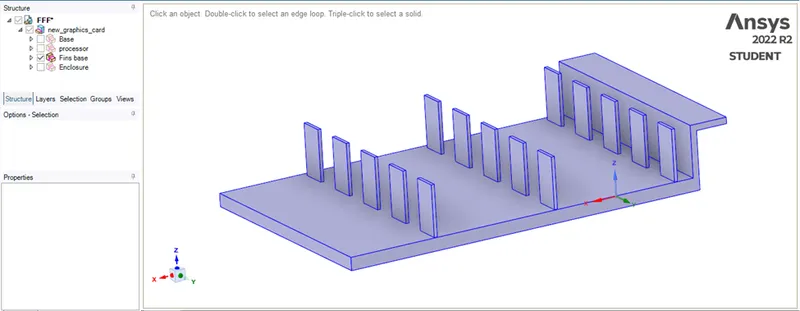
- The fins base of the graphic card is shown below,
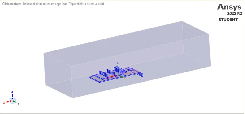
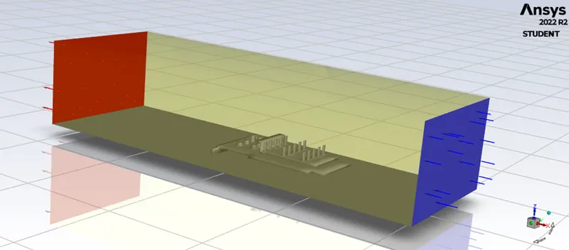
- The graphic card is enclosed with an enclosure,
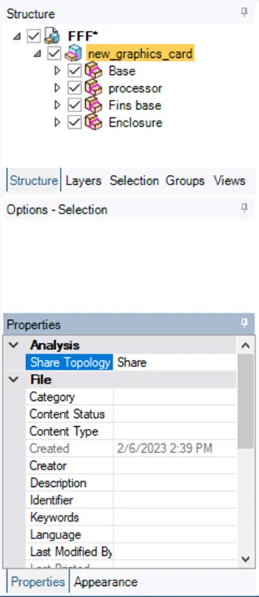
- Share topology is enabled, which allows information to be shared between different mediums.
Mesh - Meshing:
- The named selections are created as follows,
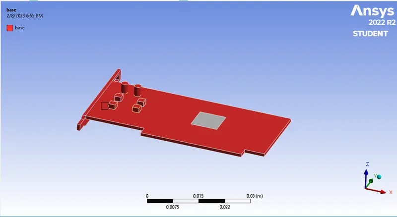
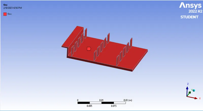
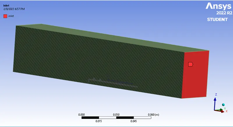
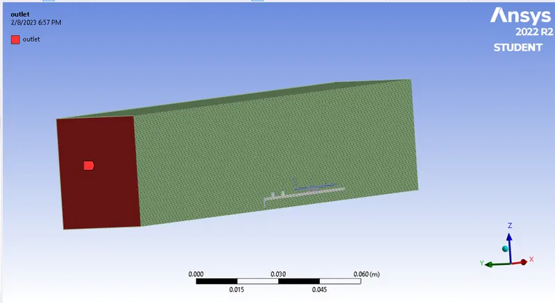
- the base wall of the enclosure is named as a wall,
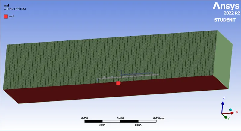
- the other 3 sides of the enclosure are named symmetry,
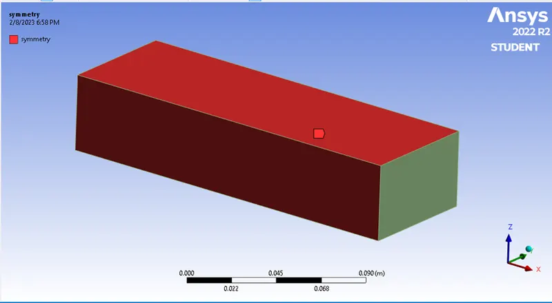
- For the baseline simulation, we use the default mesh size. Generate Mesh,
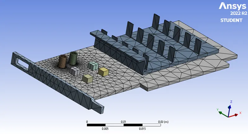
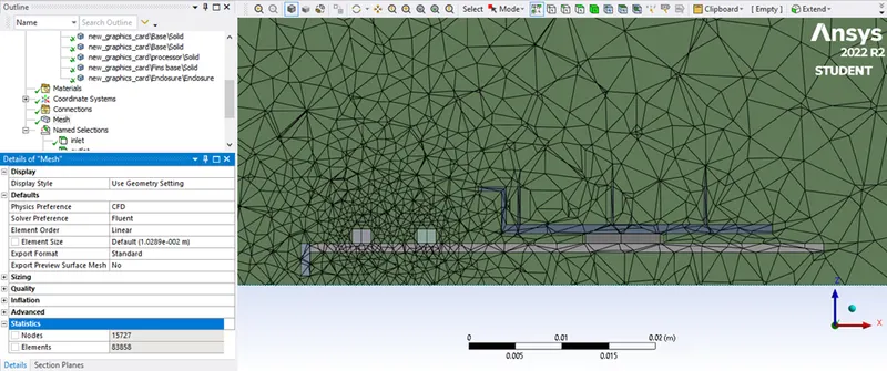
- The mesh quality is checked,
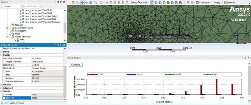
Setup - Fluent:
- The meshed geometry is loaded in ANSYS Fluent,
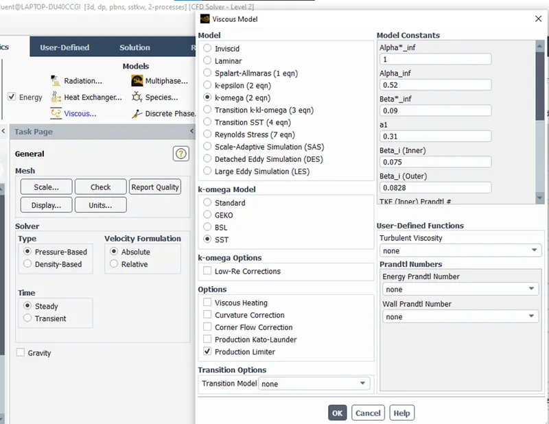
- For this simulation, the Pressure-Based solver, the steady state, and the K- omega (SST model) are used.
- Also, the energy equations are solved as we are interested in the temperature,
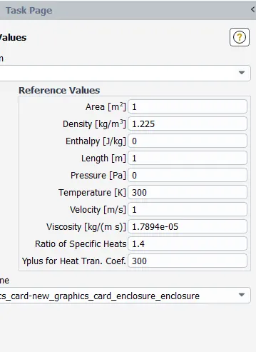
- The reference values are updated,
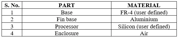
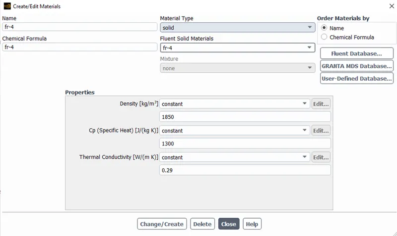
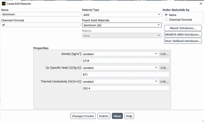
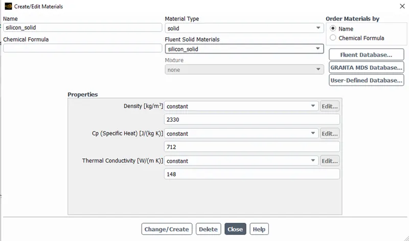
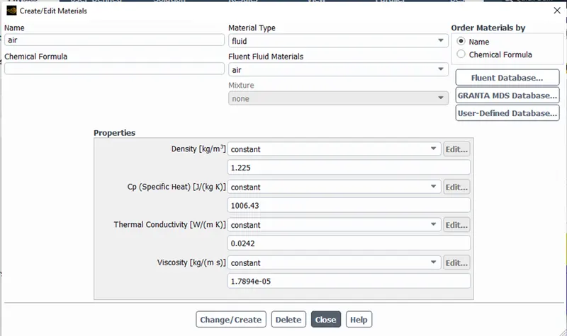
- The materials used are as follows,
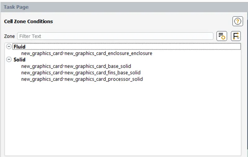
- The fluid and solid cell zones are set carefully,
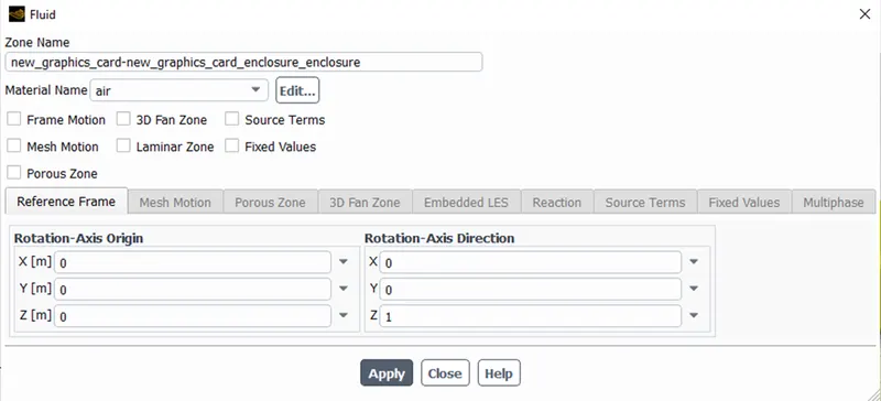
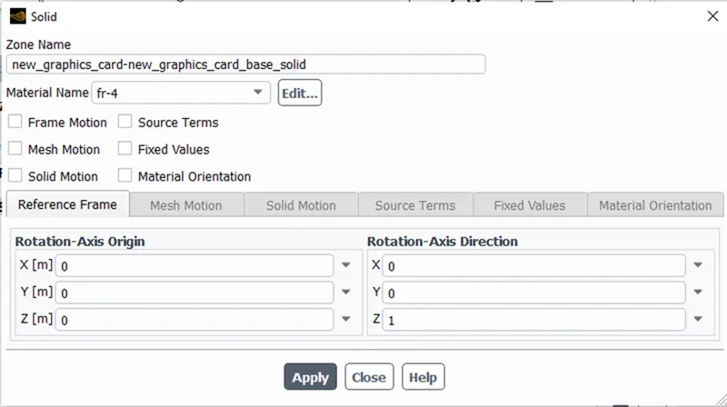
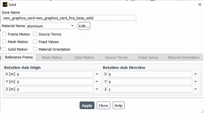
- The appropriate materials are assigned to solid and fluid zones,
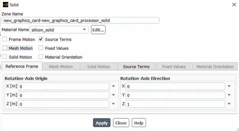
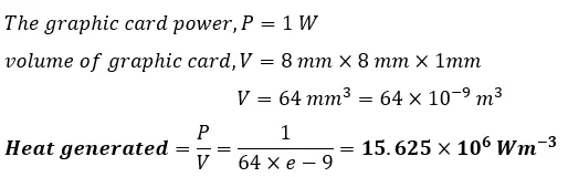
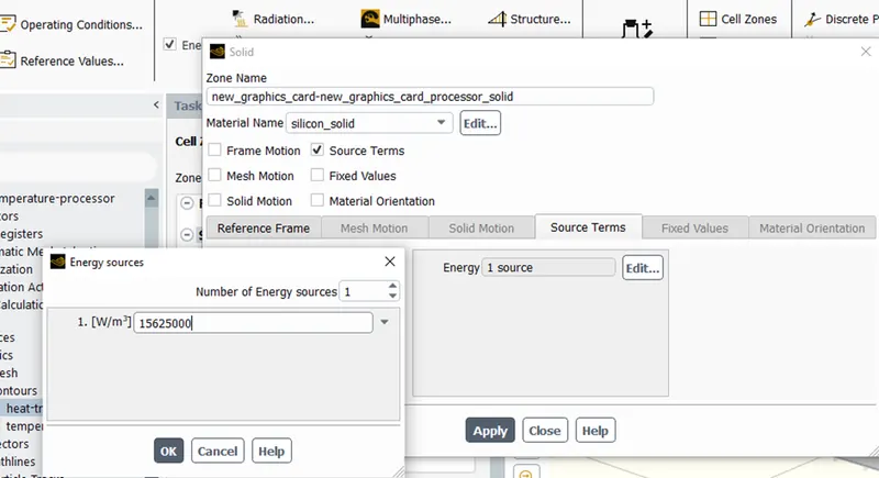
- The heat is generated by the processor, which is the heat source for this problem.
- There are different varieties of graphic cards in the market that are operated at different powers. As we have considered a scale down geometry we take power as 1 Watts.
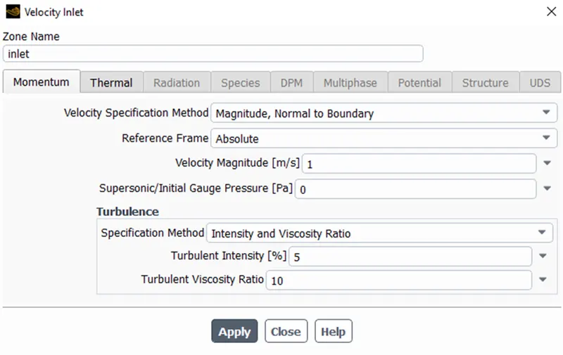
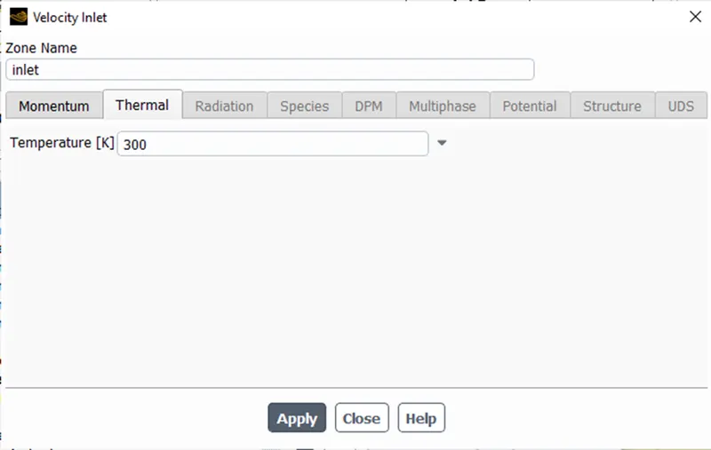
- The inlet(velocity boundary) velocity = 1 m/s and temperature = 300 K,
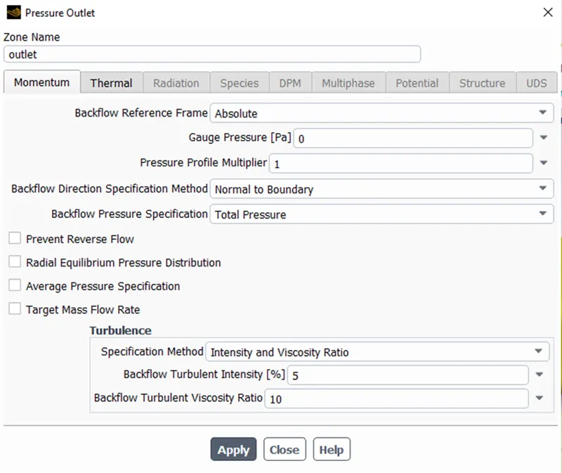
- The outlet is a pressure boundary,
- Hybrid initialization in performed.
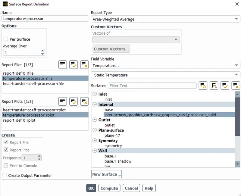
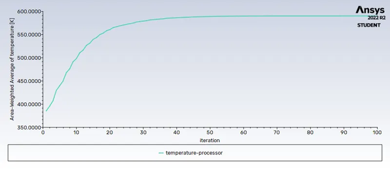
- A temperature plot is defined as follows,
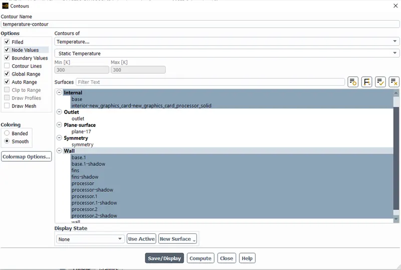
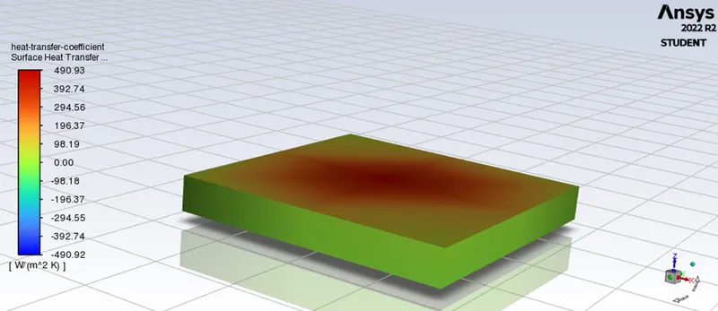
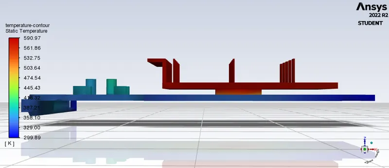
- Contours for temperature and heat transfer coefficient are created,
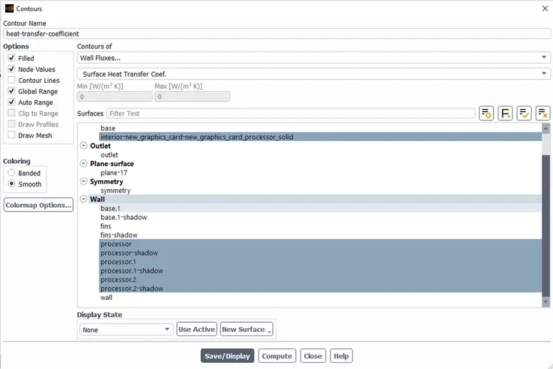
RESULTS for (a) Baseline simulation (velocity = 1m/s):
Residual plot:
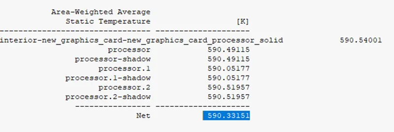
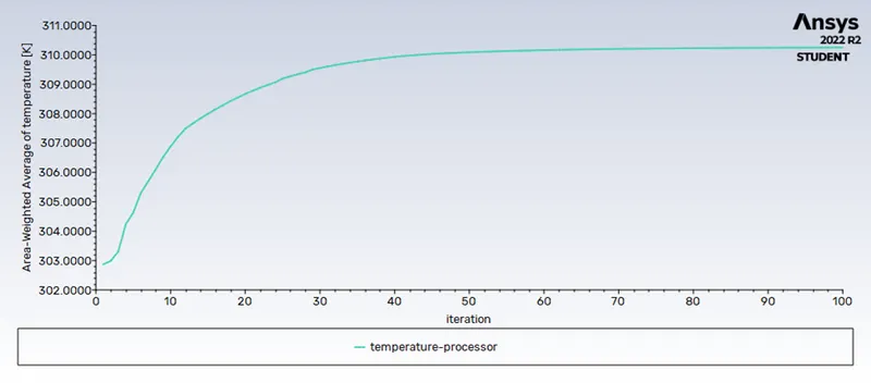
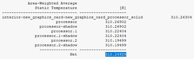
Temperature plot of the processor:
Heat transfer coefficient contour of the processor:
Temperature contour of the graphic card:
b) Refined mesh (velocity = 1 m/s, 3m/s, 5 m/s):
Mesh - Meshing:
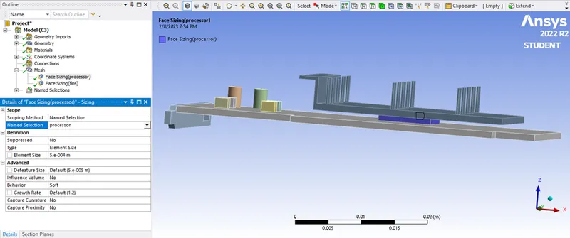
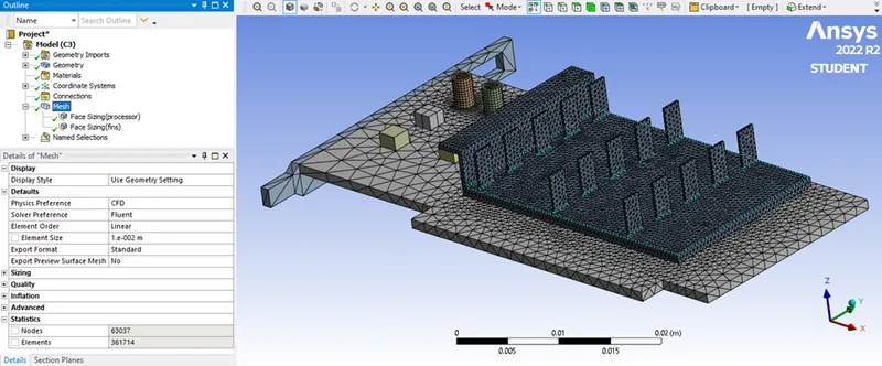
- The mesh is refined as follows,
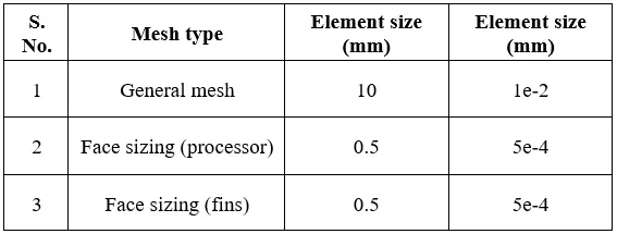
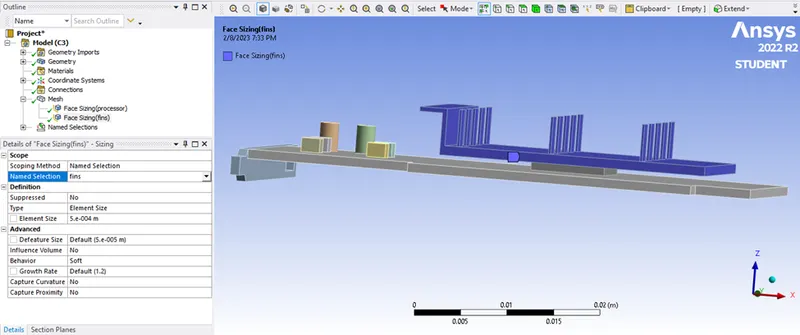
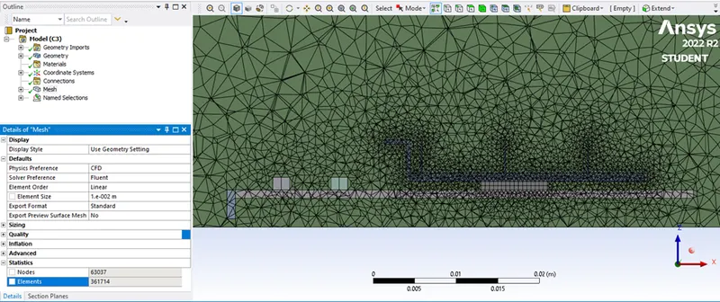
- The total number of mesh elements after refining = 0.36 million,
RESULTS for (b) Refined mesh (velocity = 1 m/s, 3 m/s, 5 m/s):
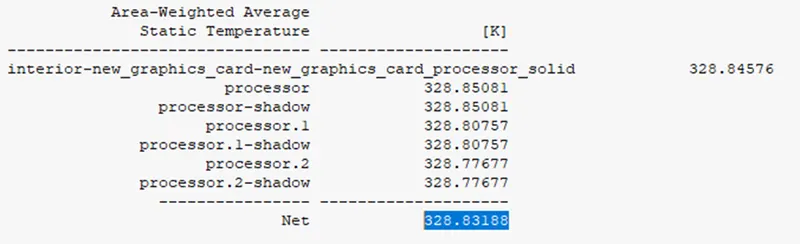
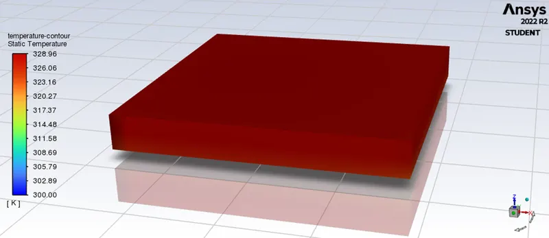
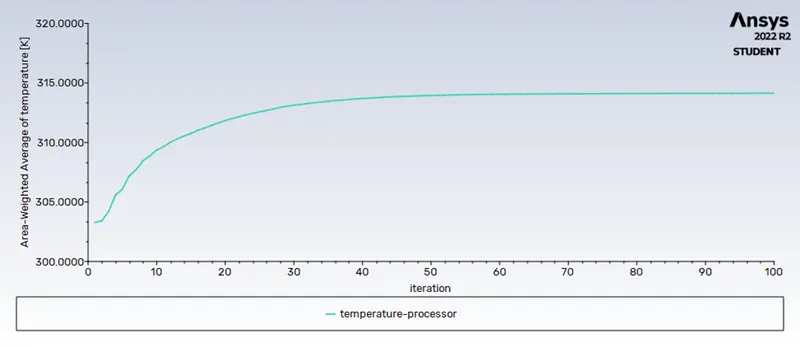
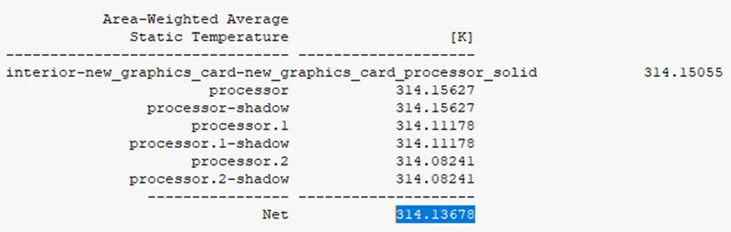
Maximum Temperature attained by the Processor:
1) For velocity = 1m/s:
2) For velocity = 3m/s:
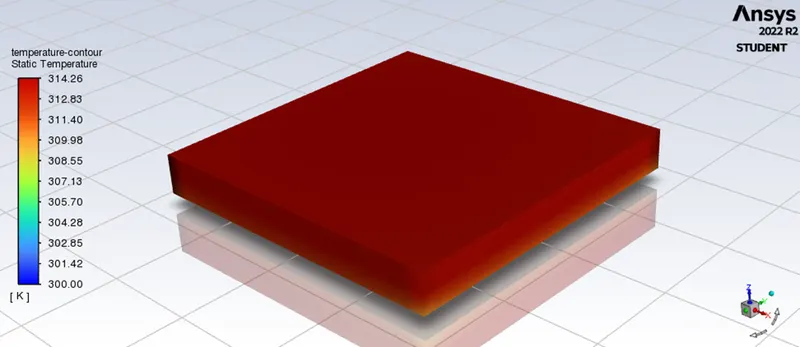
3) For velocity = 5m/s:
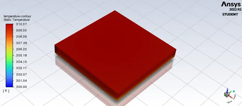
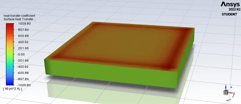
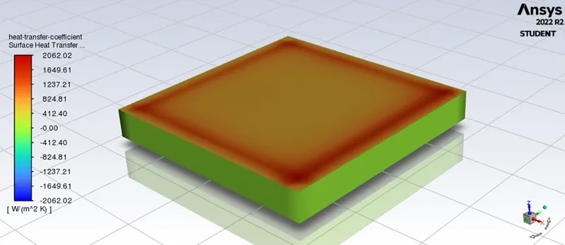
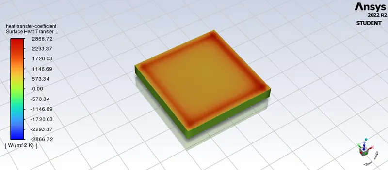
Maximum Heat transfer coefficient attained by the Processor:
1) For velocity = 1m/s:
2) For velocity = 3m/s:
3) For velocity = 5m/s:
Residual plot:
1) For velocity = 1m/s:
2) For velocity = 3m/s:
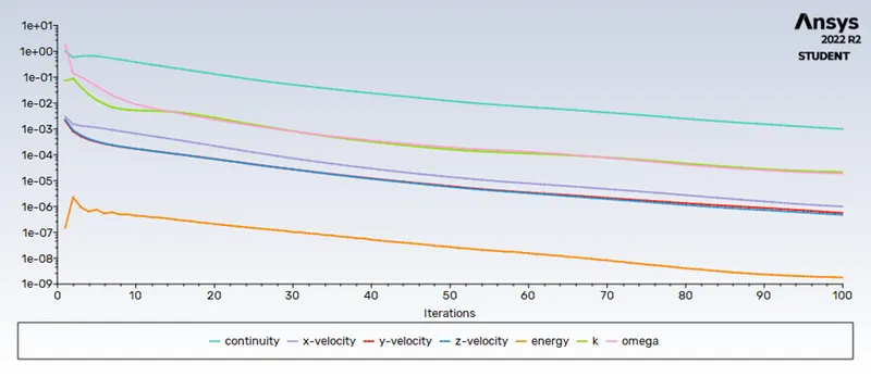
3) For velocity = 5m/s:
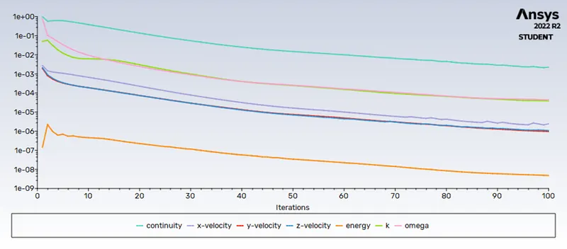
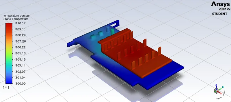
Hotspot Regions (Fins):
1) For velocity = 1m/s:
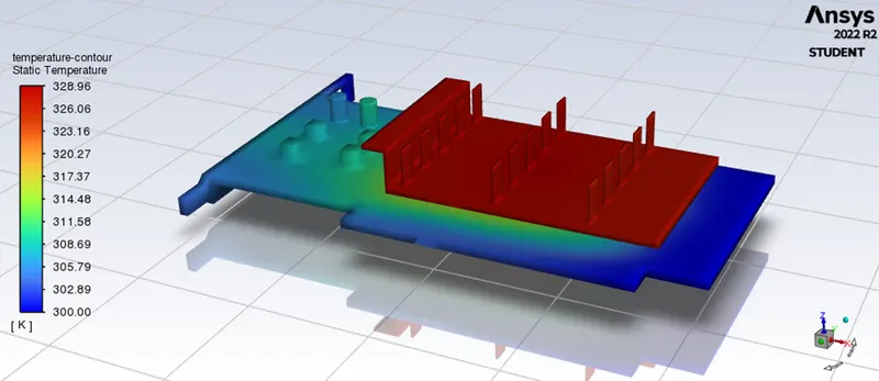
2) For velocity = 3m/s:
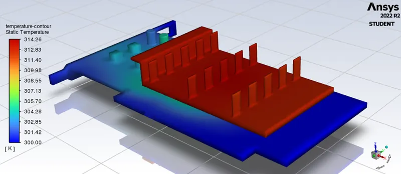
3) For velocity = 5m/s:
Hotspot Regions (Base):
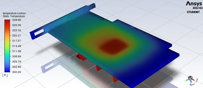
1) For velocity = 1m/s:
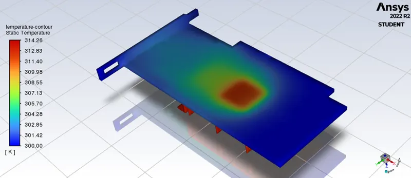
2) For velocity = 3m/s:
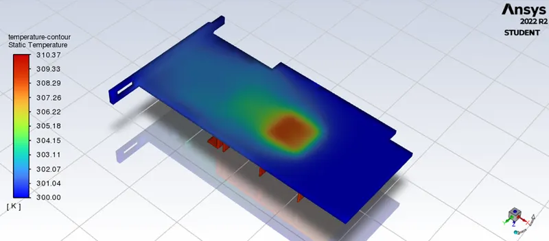
3) For velocity = 5m/s:
OBSERVATION and INFERENCE:
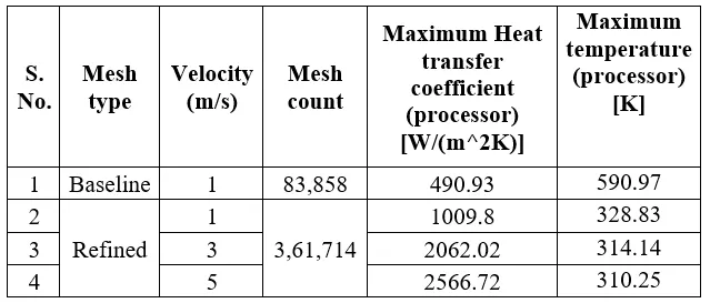
Maximum heat transfer coefficient and temperature attained by the processor:
- When the inlet velocity increased, the heat transfer coefficient of the processor increased and the temperature of the processor started to decrease.
- A higher heat transfer coefficient means greater heat dissipation to the fins from the processor.
- Thus, better cooling of the graphic card is observed for higher velocity.
Appropriate materials selection for the simulation:
- The processors are manufactured primarily from silicon due to their semi-conducting properties and stable structure.
- Aluminium or Copper is generally used for fins due to their high thermal conductivity. As aluminum is cheap, they are often preferred over copper.
- Higher thermal conductivity of fins means higher heat transfer from the processor to the atmosphere.
- The FR-4 is a glass-reinforced epoxy laminate material used for the base of the graphic card due to its low thermal conductivity.
- Due to low thermal conductivity, the FR-4 average temperature is low thus keeping the other components safe from damage.
Mesh refinement:
- As we are interested in the conduction between the processor and the fins, The mesh at the processor and the fins are refined.
Convergence:
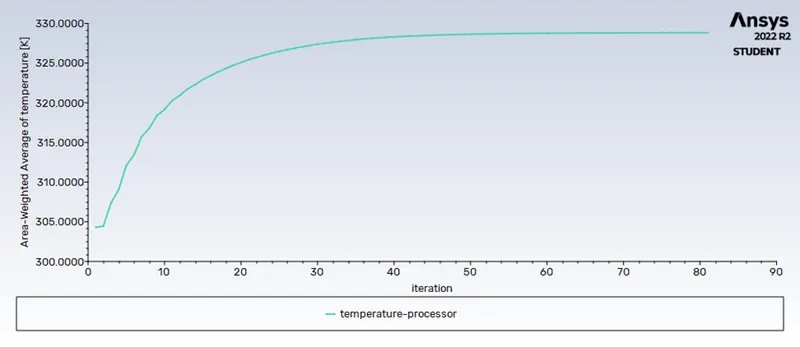
- The residual plot seems to be smooth and converging.
- The temperature plot which we were interested in reached a constant value.
Hotspots:
- Due to high thermal conductivity, the fins have a high temperature.
- Another hotspot can be observed in the PCB base where the processor is located. But due to its low thermal conductivity, the hotspot is localized near the processor thus preventing the heating of other components.
CONCLUSION:
A steady-state Conjugate Heat Transfer (CHT) analysis has been performed successfully on a graphic card.
- Appropriate materials were selected for the simulation and the Mesh refinement was explained.
- The geometry was simulated for various velocities and the results were discussed.
- The hotspots were identified and briefly discussed.