Week 6 - CHT Analysis on a Graphics card
AIM: Simulating Conjugate Heat Transfer Analysis on a Graphics card
- Run the simulation by varying the velocity from 1m/sec to 5m/sec for at least 3 velocities and discuss the results.
- Find out the maximum temperature and heat transfer coefficient attained by the processor.
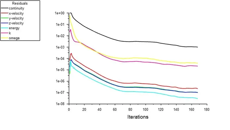
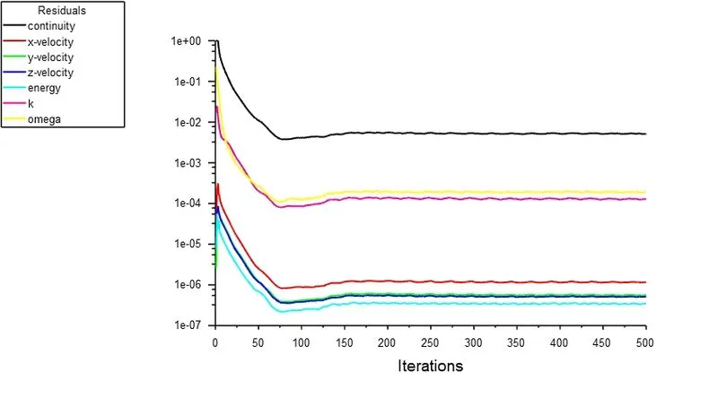
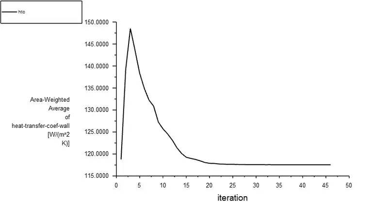
- Prove that the simulation has achieved convergence with appropriate images and plots.
- Identify potential hotspots on the model.
Introduction:
A graphics processing unit (GPU) is a specialized electronic circuit designed to rapidly manipulate and alter memory to accelerate the creation of images in a frame buffer intended for output to a display device. GPUs are used in embedded systems, mobile phones, personal computers, workstations, and game consoles. Modern GPUs are very efficient at manipulating computer graphics and image processing. Their highly parallel structure makes them more efficient than general-purpose central processing units (CPUs) for algorithms that process large blocks of data in parallel. In a personal computer, a GPU can be present on a video card or embedded on the motherboard. In certain CPUs, they are embedded on the CPU die. With the increase in the graphics processing power, there is an increase in heat generation as per the 2nd law of thermodynamics. Nowadays, the TDP of the graphics cards ranges from 60 to 400W roughly.
So, the cooling system must be designed well to avoid the high temperature destroying the expensive PCB parts.
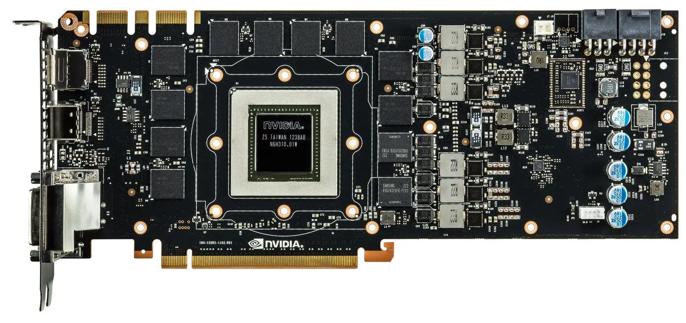
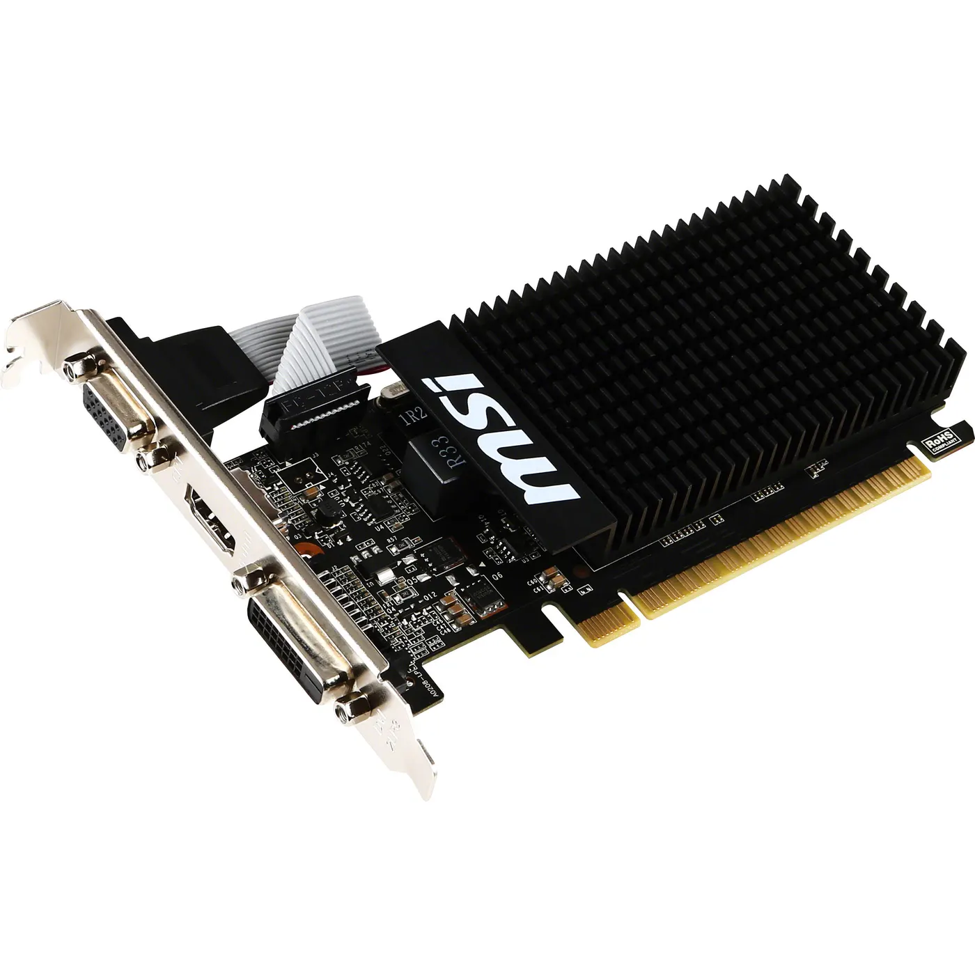
Modelling and Preparation:
The CAD model was imported onto the Spaceclaim
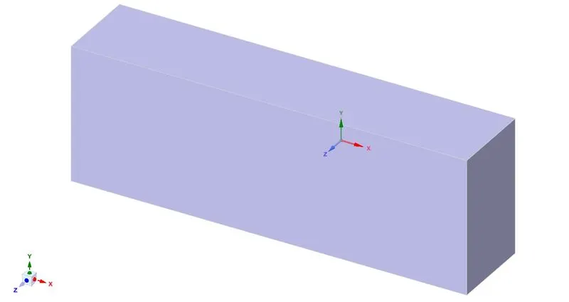
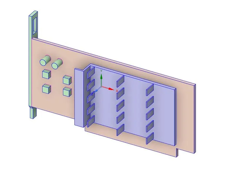
The geometry was fixed by using Share topology and checked for interference.
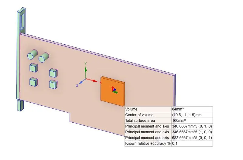
The volume of the processor is 64 mm^3.
MESH:
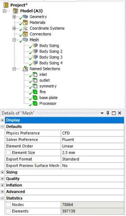
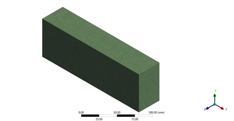
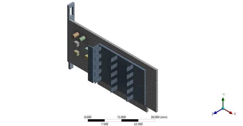
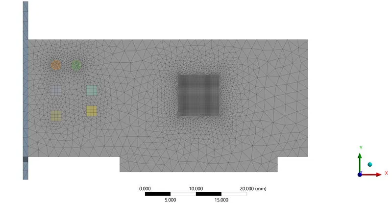
The named selections and mesh refinements were chosen as shown below:
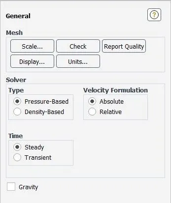
SETUP on FLUENT:
The energy was checked.
The following options were set: Viscous Mode:
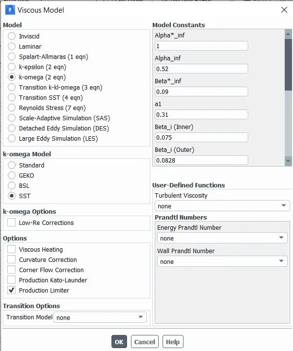
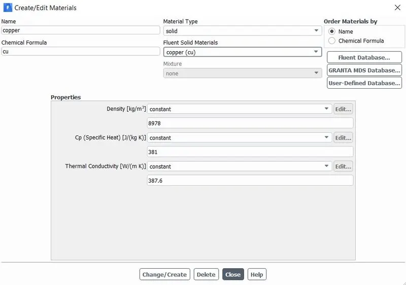
Aluminium properties: Copper properties:
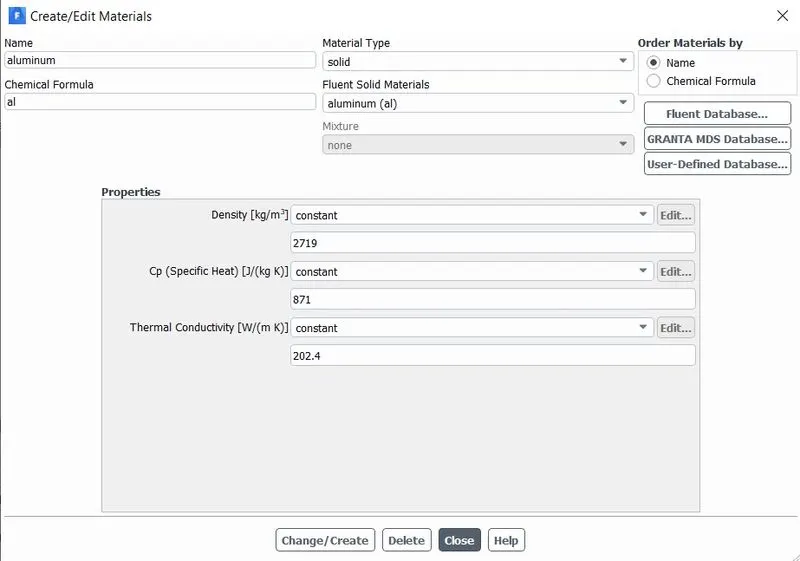
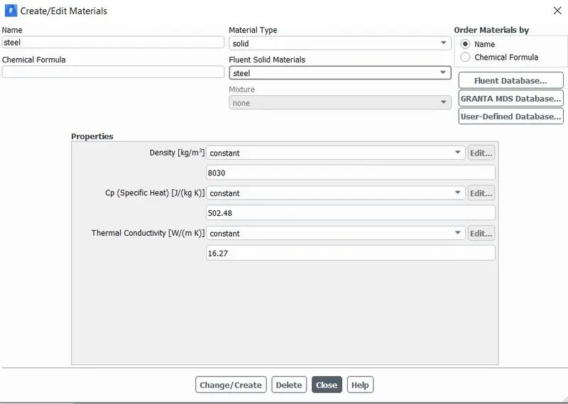
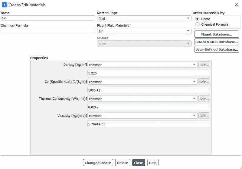
Steel properties: Air properties:
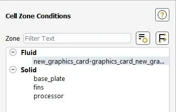
Cell Zones:
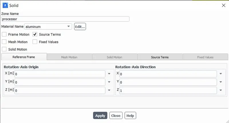
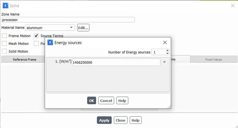
Processor:
Heat generation: a TDP of 90W was assumed and for the volume of 64 mm^3. Q= 14.0625e+09
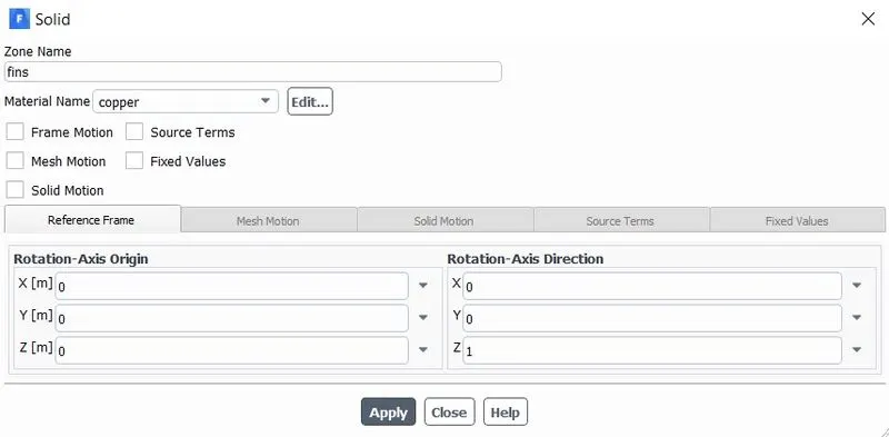
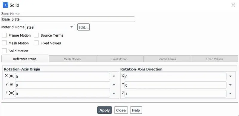
Fins and base plate:
Enclosure:
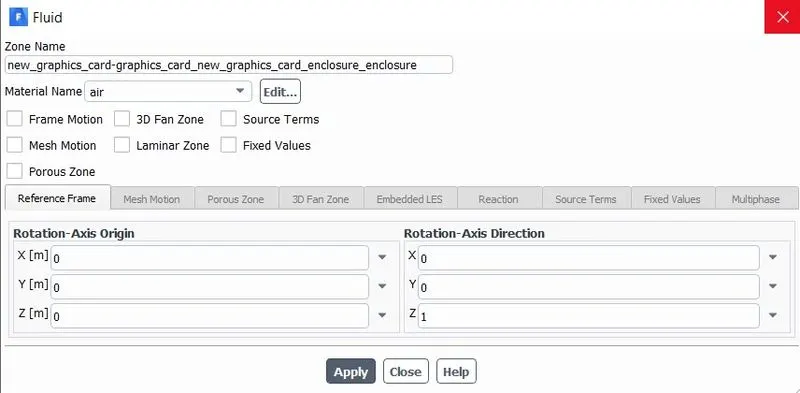
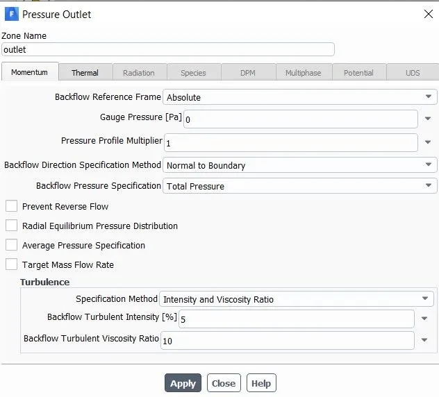
Boundary conditions:
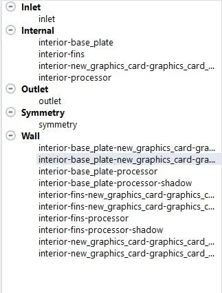
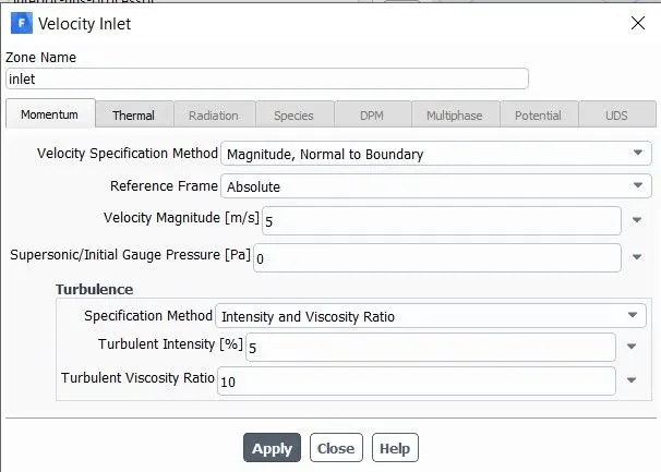
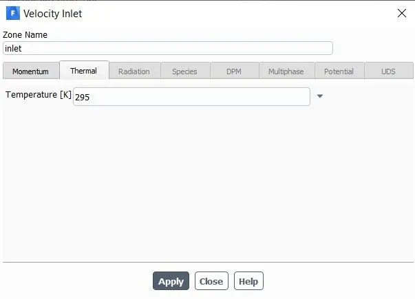
Results:
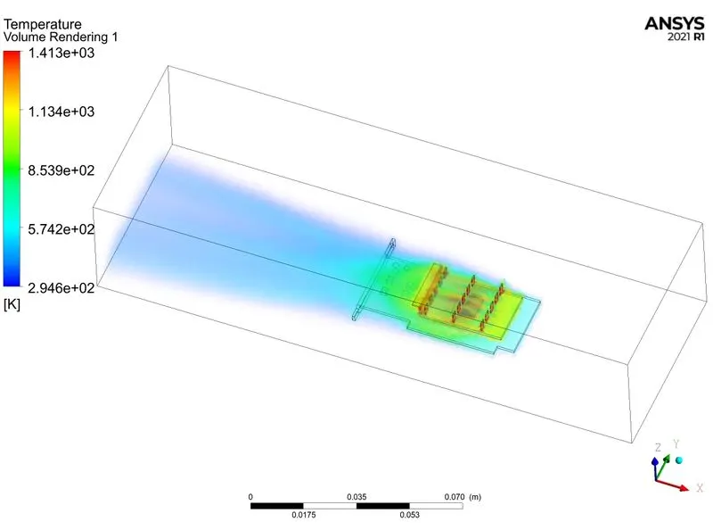
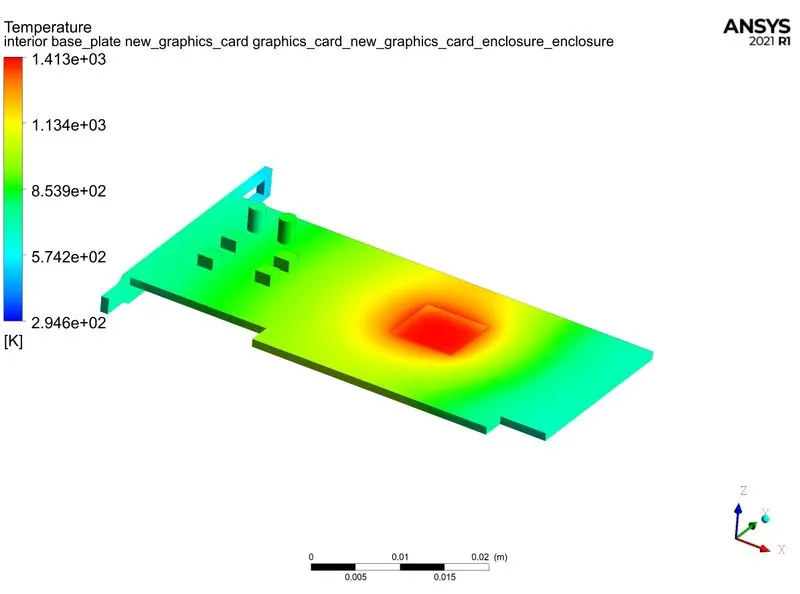
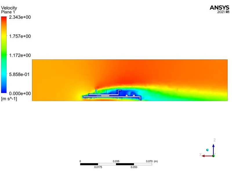
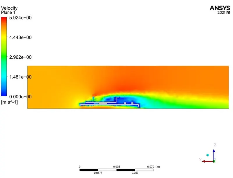
Case 1: Inlet velocity: 2 m/s
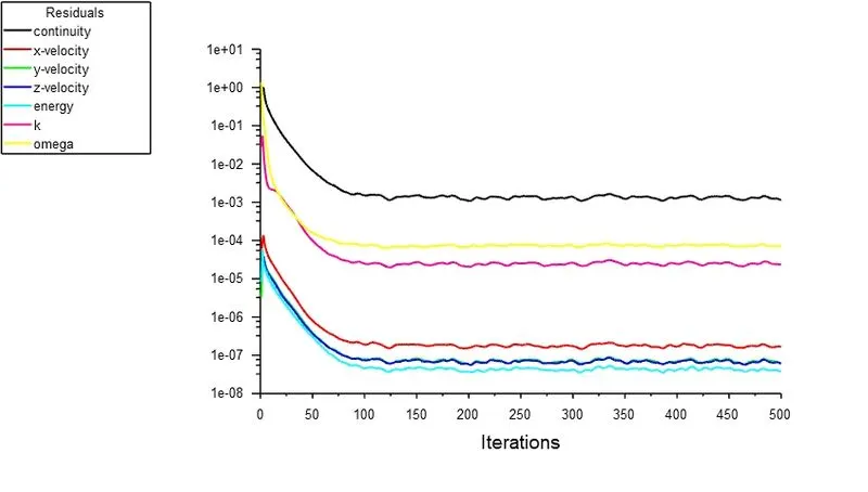
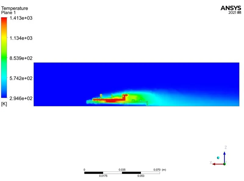
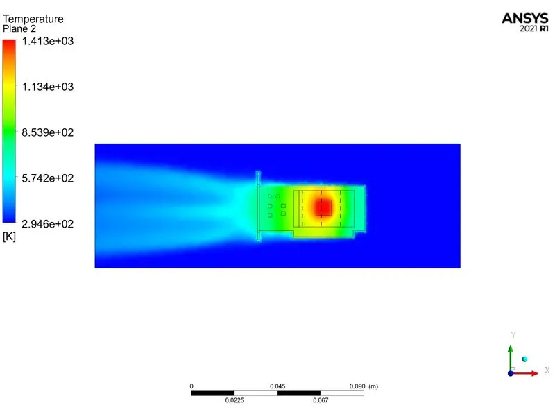
Case 2: Inlet velocity: 3 m/s
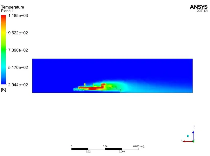
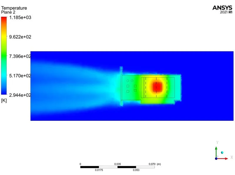
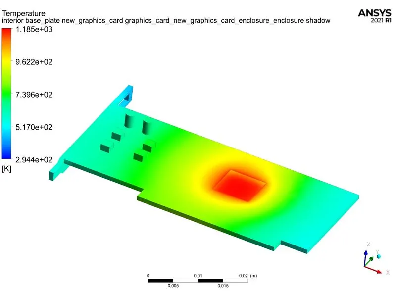
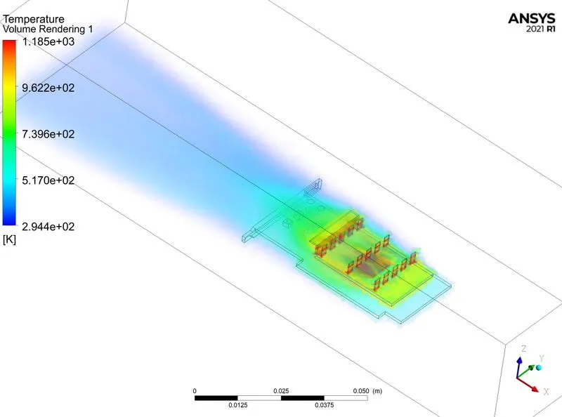
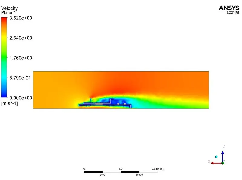
Case 3: Inlet velocity: 4 m/s
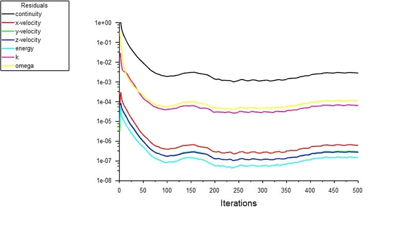
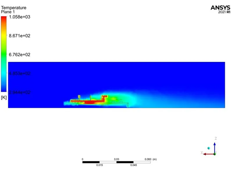
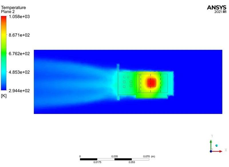
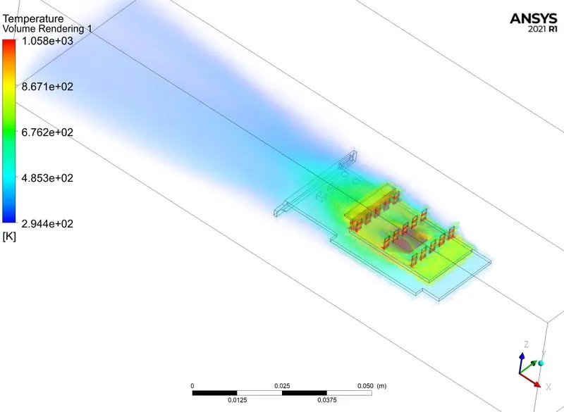
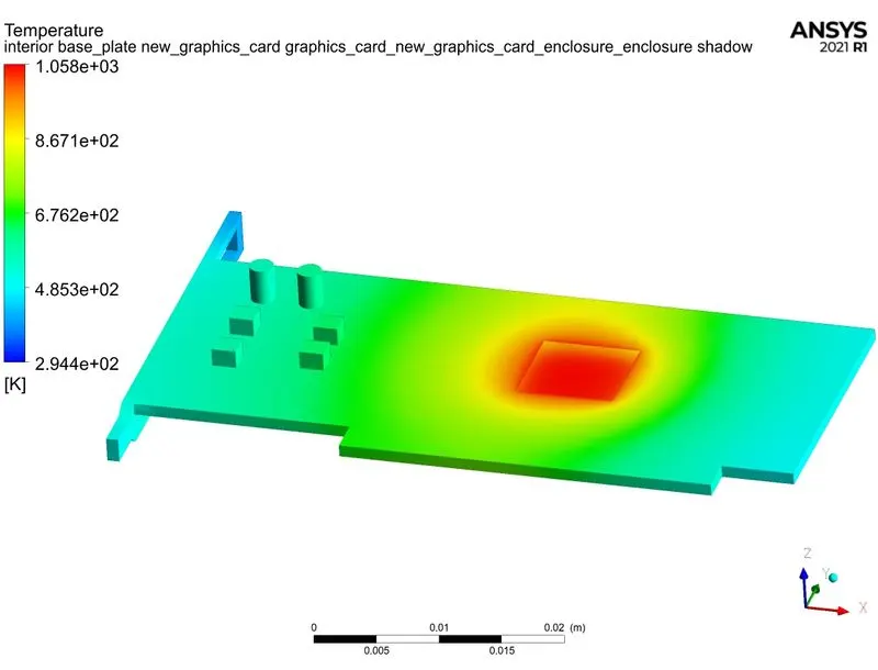
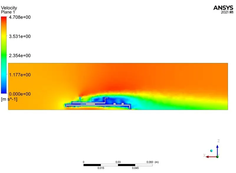
Case 4: Inlet velocity: 5 m/s
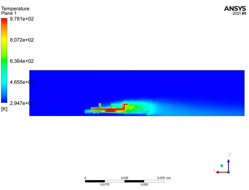
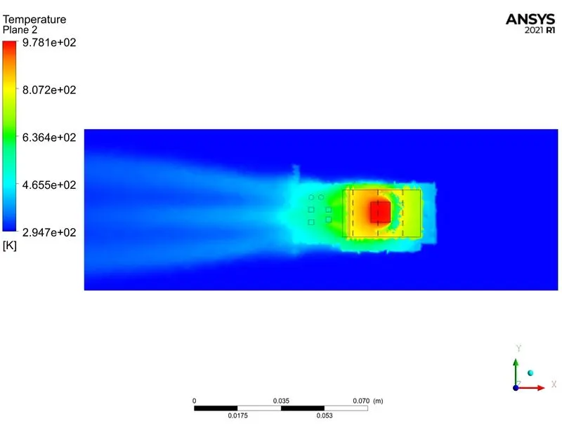
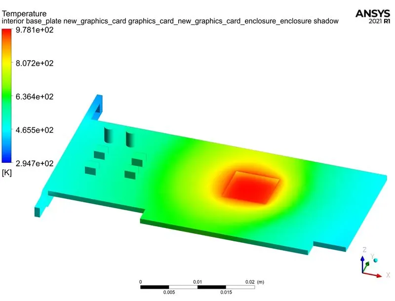
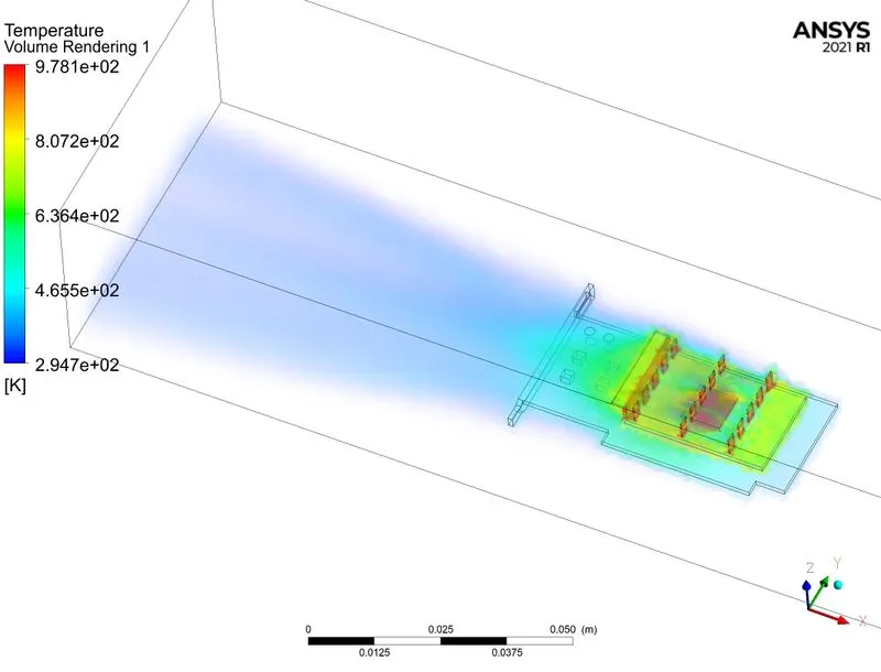
Heat Transfer coefficient of the processor:
HTC of the processor: 117.55046 W/(m^2-K)
Conclusion:
1. The temperature hotspots are mainly at the processor and the fins.
2. As the inlet velocity of the air is increased more heat is dissipated thereby keeping the GPU cooler.
3. As the mesh is refined, fairly accurate results were obtained.