Week 8 - Simulating Cyclone separator with Discrete Phase Modelling
Aim:
To perform analysis on cyclone separator and calculate the separation efficiency and pressure drop.
Objective:
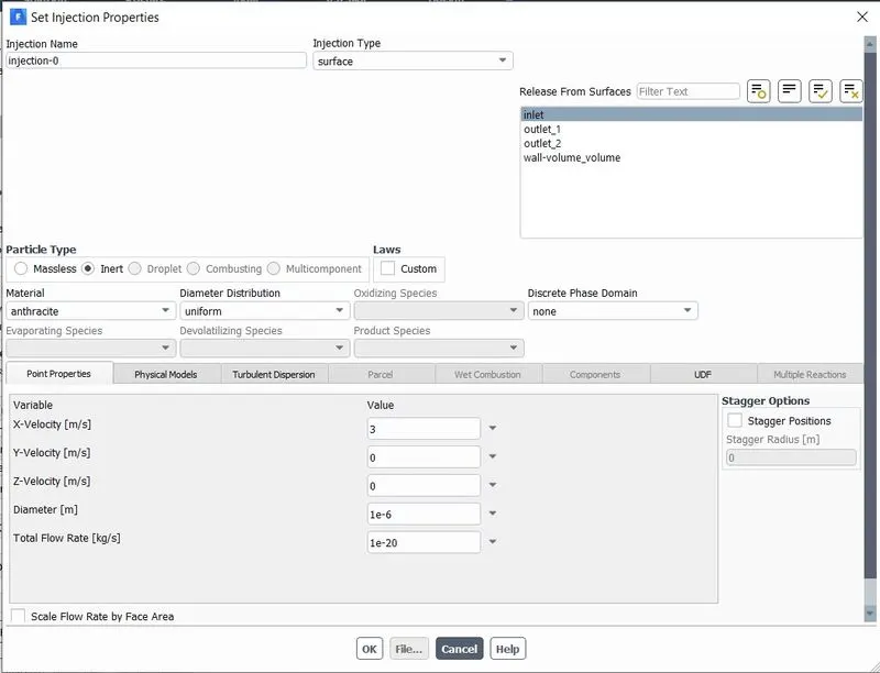
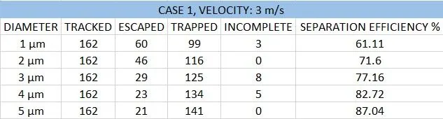
- To perform an analysis on a given cyclone separator model by varying the particle diameter from 1 μm to 5μm and calculate the separation efficiency in each case. Discuss the results. [Use both the velocity's as 3m/sec.]
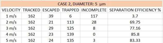
- To perform an analysis on a given cyclone separator model by varying the particle velocity from 1 m/sec to 5 m/sec and calculate the separation efficiency and pressure drop in each case. Discuss the results. [Use particle diameter size as 5 μm for all cases & keep flow velocity same as particle velocity]
Introduction:
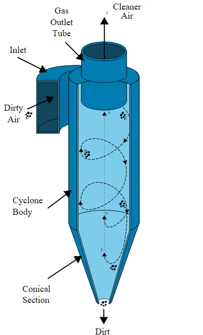
Cyclone separators provide a method of removing particulate matter from air or other gas streams at low cost and low maintenance. Cyclones are somewhat more complicated in design than simple gravity settling systems, and their removal efficiency is much better than that of settling chamber. Cyclones are basically centrifugal separators, consists of an upper cylindrical part referred to as the barrel and a lower conical part referred to as a cone. They simply transform the inertia force of gas-particle flows to a centrifugal force by means of a vortex generated in the cyclone body. The particle-laden air stream enters tangentially at the top of the barrel and travels downward into the cone forming an outer vortex. The increasing air velocity in the outer vortex results in a centrifugal force on the particles separating them from the air stream. When the air reaches the bottom of the cone, it begins to flow radially inwards and out the top as clean air/gas while the particulates fall into the dust collection chamber attached to the bottom of the cyclone.
Cyclones have no moving parts and available in many shapes and sizes, for example from the small 1 and 2 cm diameter source sampling cyclones which are used for particle size analysis to the large 5 m diameter cyclone separators used after wet scrubbers, but the basic separation principle remains the same.
Cyclone performance
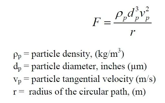
Cyclones are basically centrifugal separators. They simply transform the inertia force of gas-particle to a centrifugal force by means of a vortex generated in the cyclone body. The particle-laden gas enters tangentially at the upper part and passes through the body describing the vortex. Particles are driven to the walls by centrifugal forces of the cyclone leg. In the lower section, the gas begins to flow radially inwards to the axis and spins upwards to the gas outlet duct.
1. Cut diameter
The cut diameter of the cyclone is defined as the size of the particles collected with 50% collection efficiency. It is an indicator of the size range of particles that can be collected. It is a convenient way of defining as it provides information on the effectiveness of a particle size range. A frequently used expression for cut off diameter is:
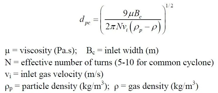
A value of N, number of turns, must be known in order to solve equation (5.2) for dpc.
Given the volumetric flow rate, inlet velocity, and dimension of the cyclone, N can be
easily calculated. Values of N can vary from 1 to 10, with typical values in the 4-5 range.
2. Collection efficiency
The collection or separation efficiency is most properly defined for given particle size. As mentioned, fractional efficiency is defined as the fraction of particles of a given size collected in the cyclone, compared to those of that size going into the cyclone. Experience shows that the collection efficiency of cyclone separator increases with increasing particle mean diameter and density; increasing gas tangential velocity; decreasing cyclone diameter; increasing cyclone length; extraction of gas along with solids through the cyclone legs. Several equations have been developed to predict the collection efficiency in cyclones through correlation equations. The following section describes two methods of calculating cyclone efficiency. First, the theory proposed by Leith and Licht (1973) for calculating fractional efficiency will be discussed and then a convenient graphical method developed by Lappel (1951) will be presented. The fractional efficiency equation of Leith and Licht is given as:
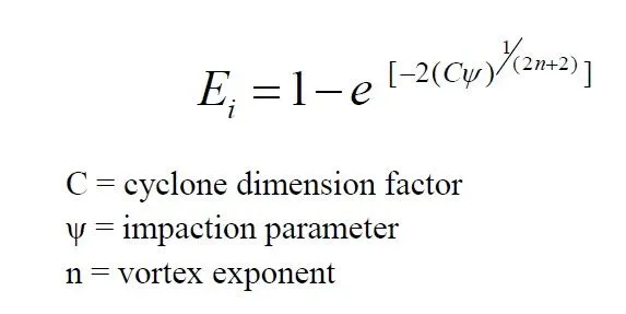
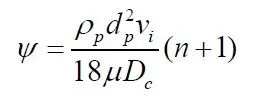
In this expression, c is a factor that is a function only of the cyclone’s dimensions. The symbol ψ expresses characteristics of the particles and gas and is known as inertia or impaction parameter. The value of n is dependent on the cyclone diameter and temperature of the gas stream. And ρp times vi expresses the particle’s initial momentum. Although the calculation involved in this method is tedious but are straightforward.
3. Pressure Drop:
Pressure drop across the cyclone is of much importance in a cyclone separator. The pressure drop significantly affects the performance parameters of a cyclone. The total pressure drop in a cyclone will be due to the entry and exit losses, and friction and kinetic energy losses in the cyclone. Normally most significant pressure drop occurs in the body due to swirl and energy dissipation. There have been many attempts to predict pressure drops from design variables. The idea is that by having such an equation, one could work back and optimize the design of new cyclones. The empirical equation given by Stairmand (1949) can be used to estimate the pressure drop.
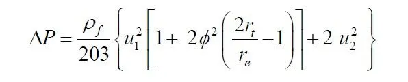
ΔP = cyclone pressure drop
ρf = gas density; u1 = inlet duct velocity;
u2 = exit duct velocity
rt = radius of the circle to which the centre line of the inlet is tangential;
re = radius of the exit pipe
phi = cyclone pressure drop factor
4. Separation Efficiency:
it is the ratio of particles of a given size, trapped in the separator to the particles then entered the separator.
It increases with particle size, density, inlet velocity, etc.
Modelling and Preparation:
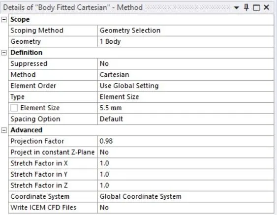
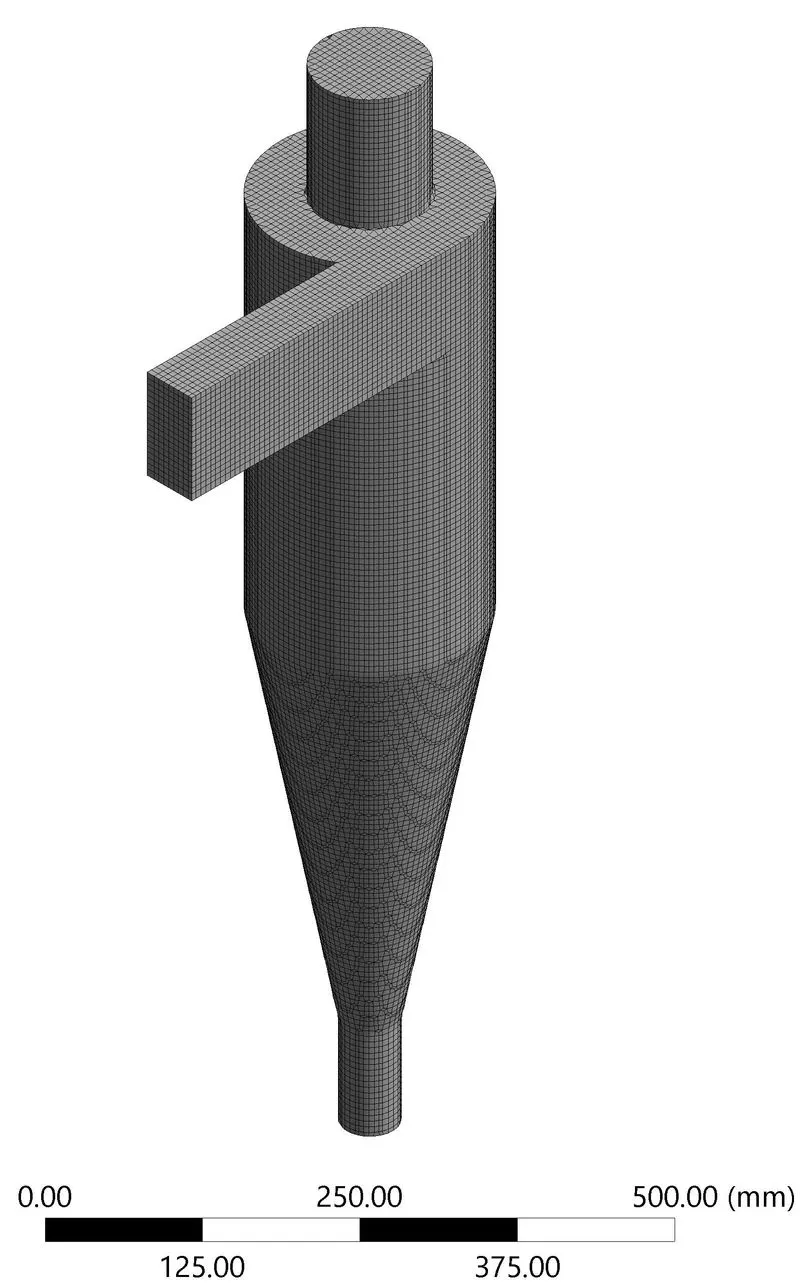
The Cyclone Separator CAD model was imported onto the Spaceclaim, volume was extracted, and suppressed the physics of the original model.
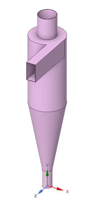
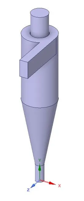
3D CAD MODEL EXTRACTED VOLUME
Mesh: Cell Count: 257054
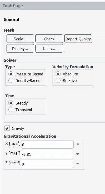
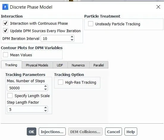
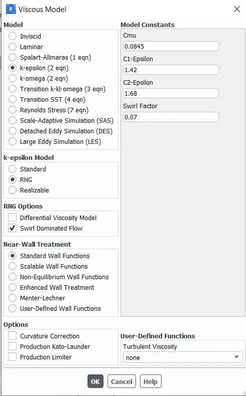
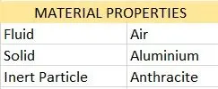
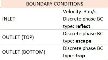
SETUP in FLUENT:
Results:
CASE 1:
1. Inlet velocity: 3 m/s1, Diameters: 1 µm
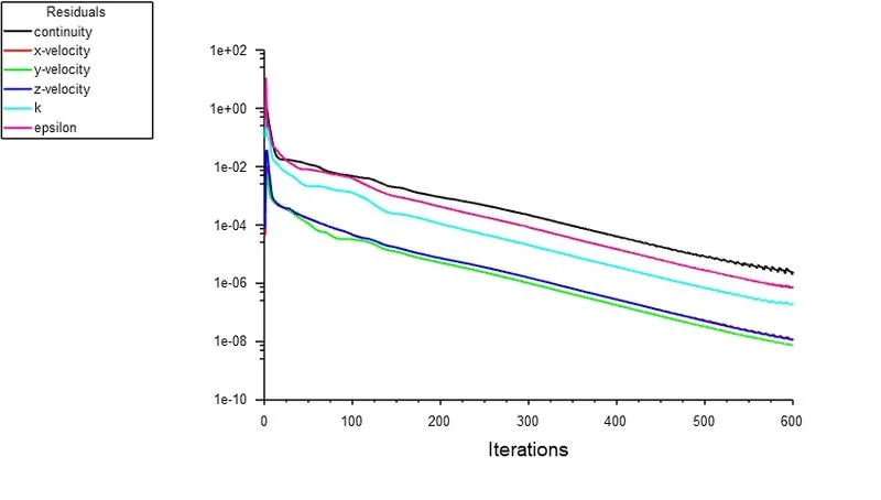
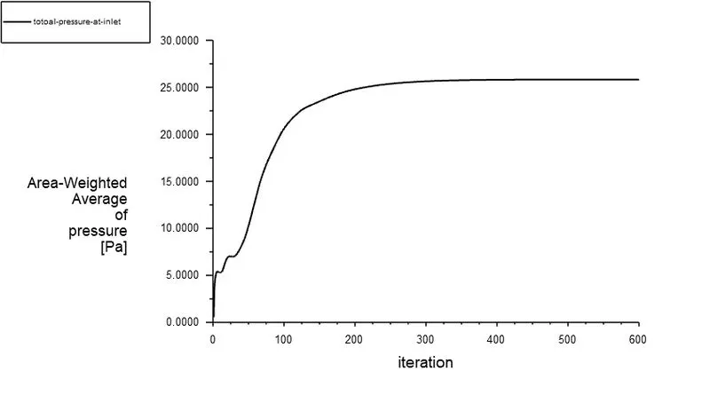
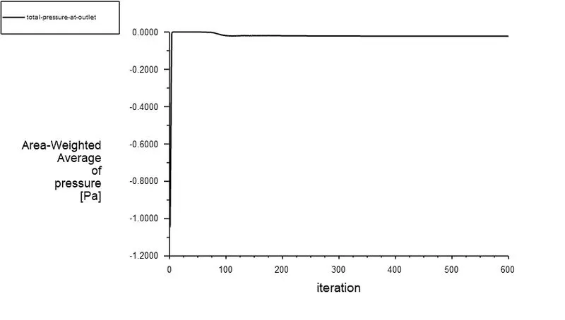
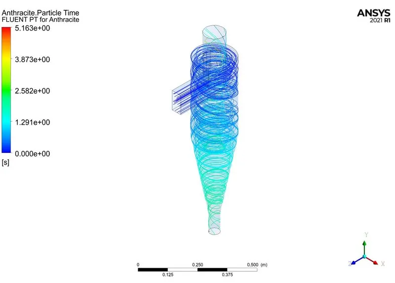
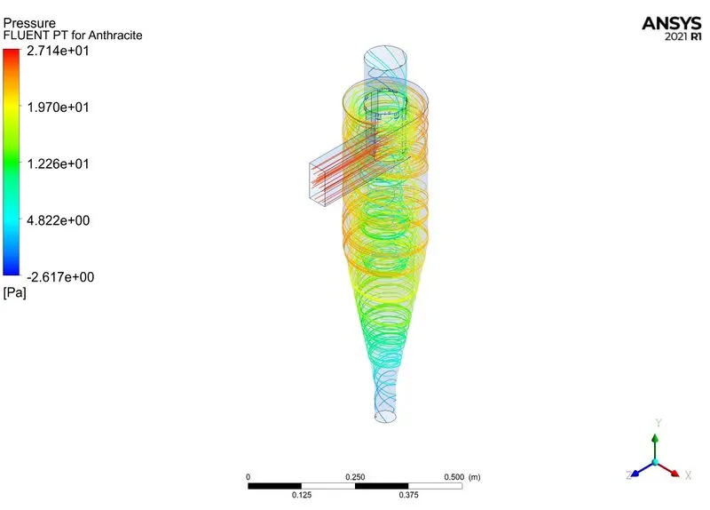
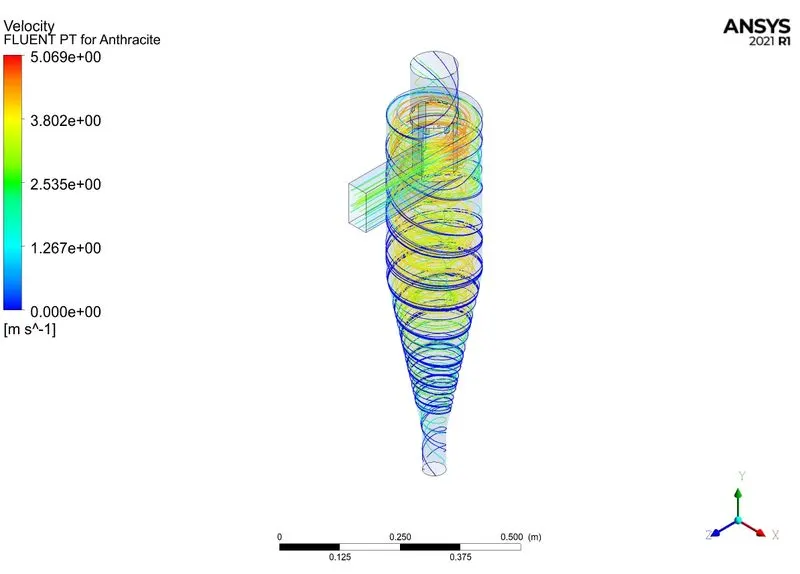
2. Inlet velocity: 3 m/s1, Diameters: 2 µm
3. Inlet velocity: 3m/s, Diameter: 3 µm
4. Inlet velocity: 3m/s, Diameter: 4 µm
5. Inlet velocity: 3m/s, Diameter: 5 µm
CASE 2:
1. Inlet velocity: 1m/s, Diameter: 5 µm
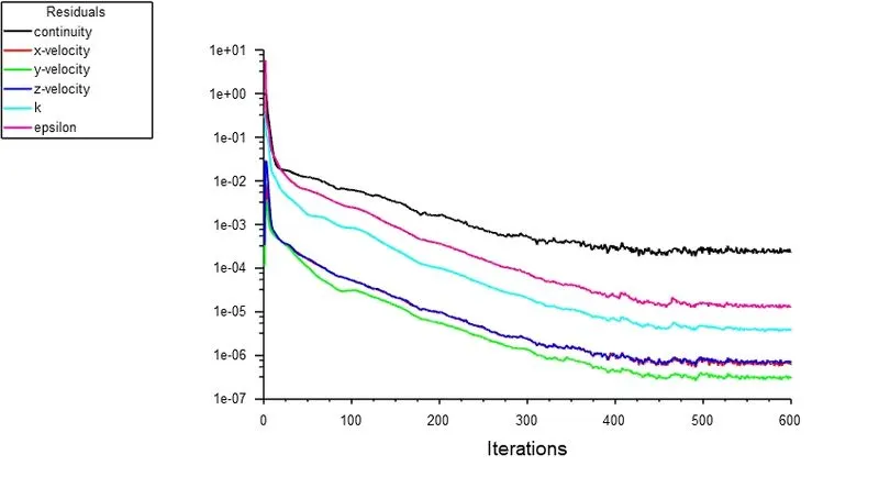
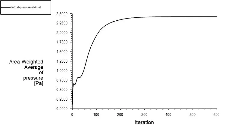
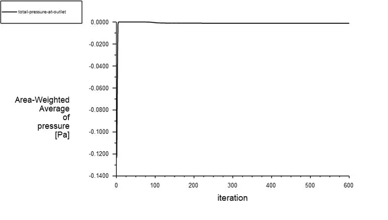
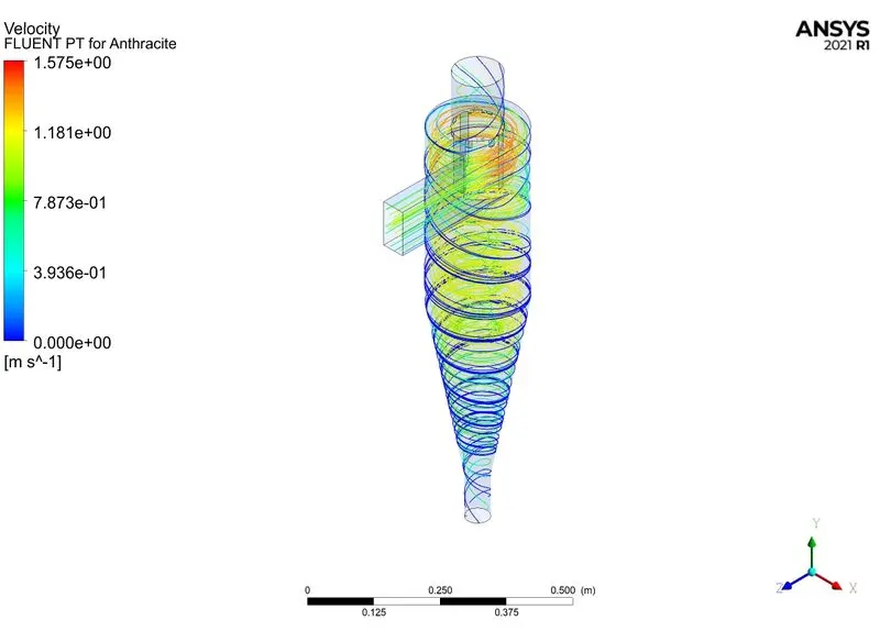
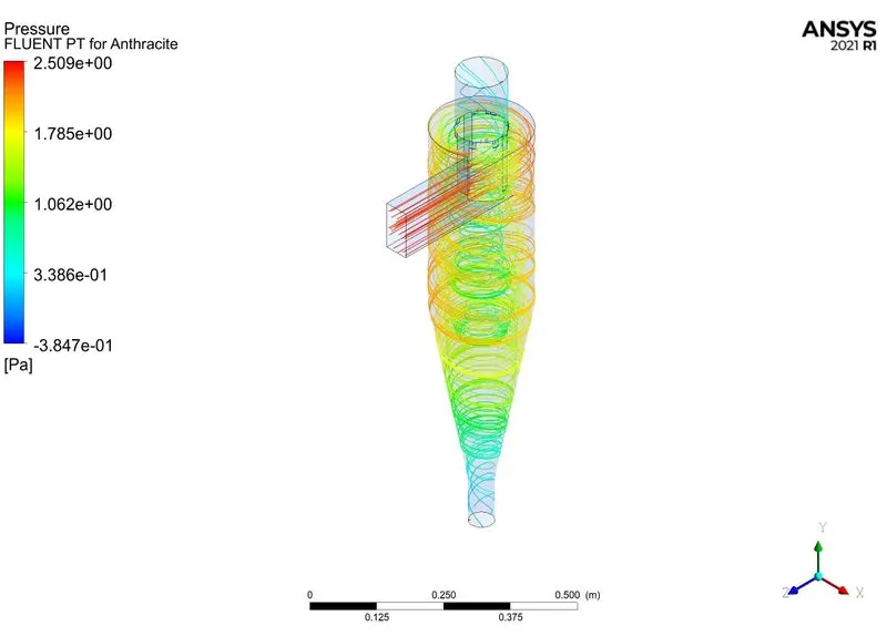
2. Inlet velocity: 2m/s, Diameter: 5 µm
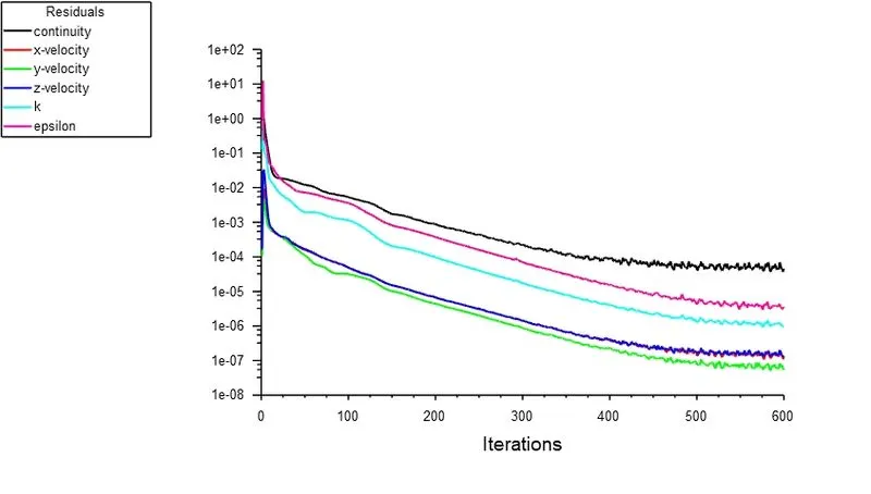
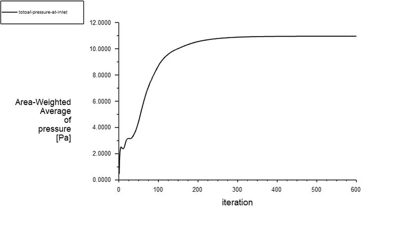
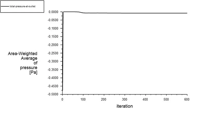
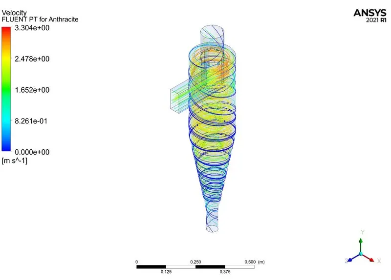
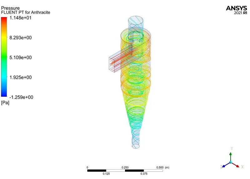
3. Inlet velocity: 4m/s, Diameter: 5 µm
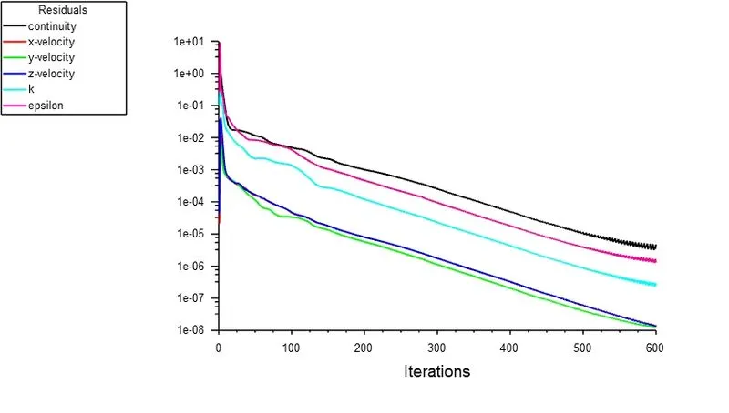
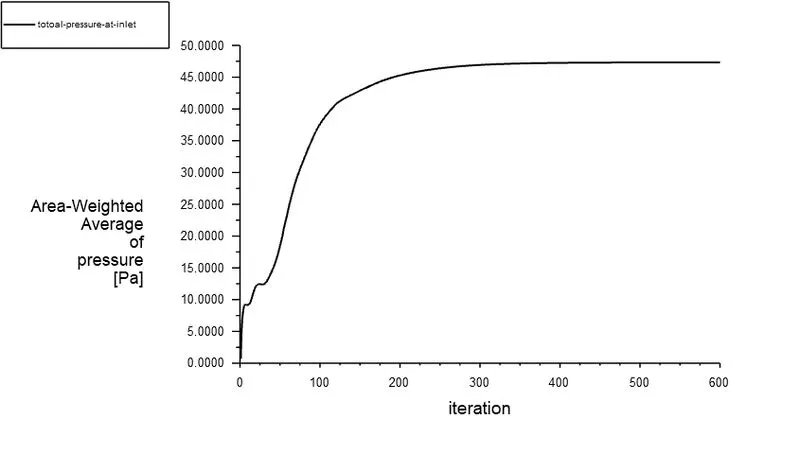
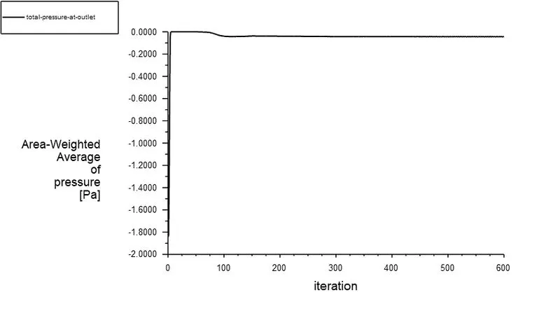
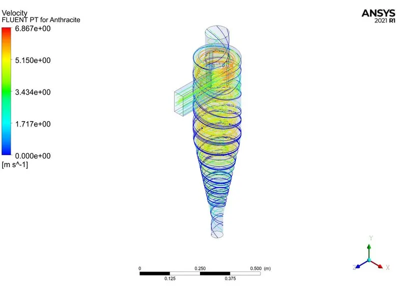
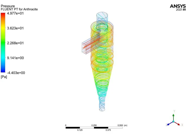
4. Inlet velocity: 5m/s, Diameter: 5 µm
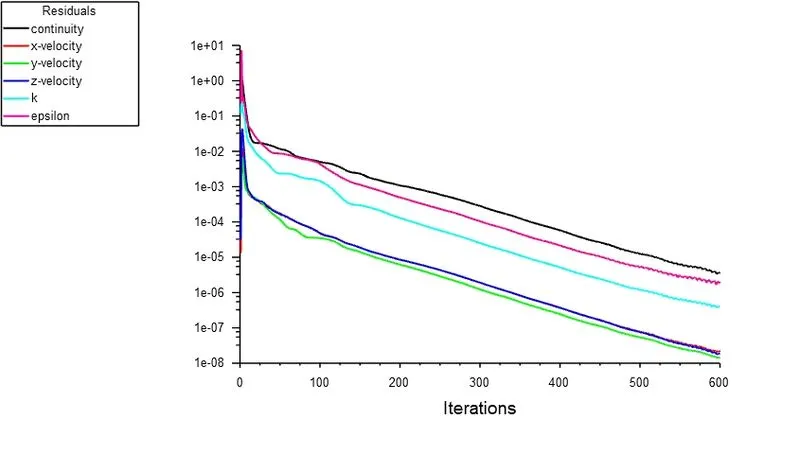
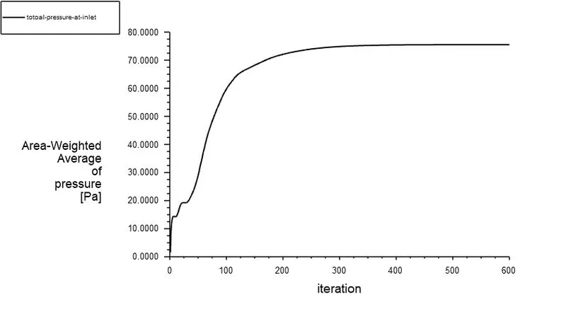
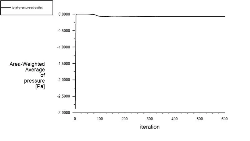
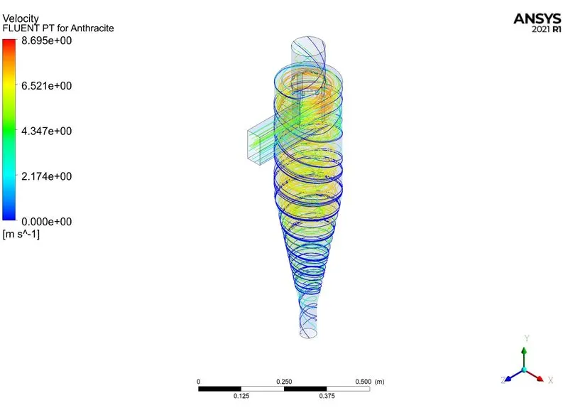
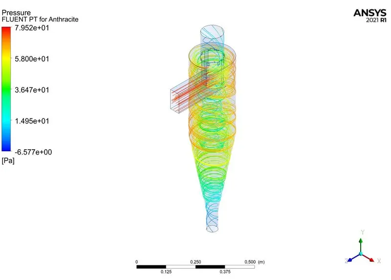
Conclusion:

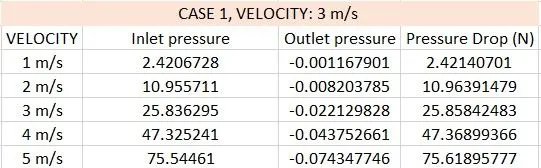
1. With the increase in inlet velocity, the pressure drop increases for a particular diameter of the particle.
2. with the increase in diameter of the particle, the pressure drop remains the same for a particular inlet velocity.
3. The separation efficiency increases with an increase in inlet velocity and particle diameter.