Week 6 - CHT Analysis on a Graphics card
ABSTRACT:
A steady-state conjugate heat transfer analysis on a model of a graphics card.Using appropriate choice of materials for the simulation. Making sure to properly define the correct solid and fluid zones.Running the simulation for best possible mesh with combination of refined mesh in different regions. Explain the reason for choosing the particular mesh settings. Running the simulation by varying the velocity from 1m/sec to 5m/sec for at least 3 velocities. Finding out the maximum temperature and heat transfer coefficient attained by the processor. Identifying the potential hotspots on the model.
Conjugate Heat Transfer (CHT) analysis type allows for the simulation of heat transfer between solid and fluid domains by exchanging thermal energy at the interfaces between them.
Graphics card is a hardware which is used to increase the video memory of a computer, and make its display quality more high-definition. It makes the computer more powerful and gives it the capacity to do more high-level works. The quality of the image depends on the quality of the graphics card. It is very much important for gaming and video editing on a PC. Every game needs a graphics memory to start and it depends on the type of the game, and the requirements are mentioned on the game box.[2]
Graphics Card has 3 Major components:
- Fins
- Processors
- Base
Fins: The reason is because it conducting the heat away from the component and than cooling down with air, it far more efficient. It has high thermal Conductivity. They are made up of copper and aluminium. Below Geometry is of Fins.
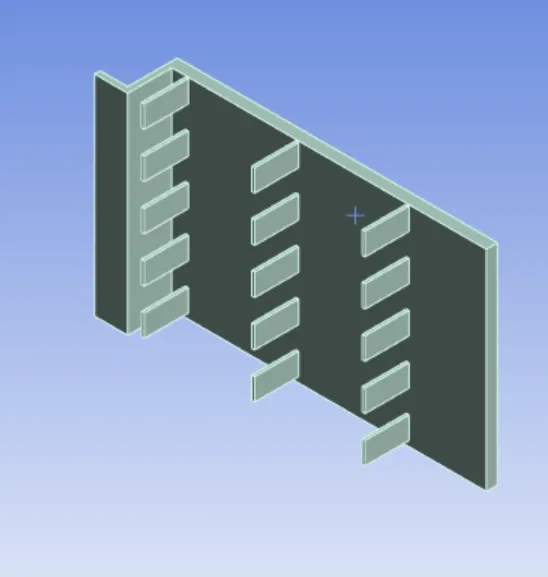
Processor: A specialized processor originally designed to accelerate graphics rendering. GPUs can process many pieces of data simultaneously, making them useful for machine learning, video editing, and gaming applications. It is the heart of the chip made up of Silicon and germanium. It produces the heat while running the chip. Below Geomtry is processor.

Base: It holds the processor, fins and the other components of the graphic unit. The base is made up of ABS(Acrylonitrile butadiene styrene). Below geomtry is of base with components.
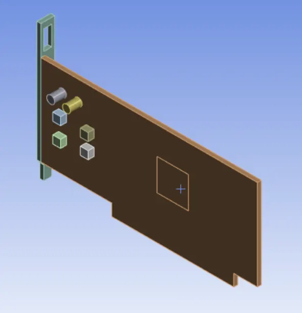
The combining geometry of the graphics user interface card:
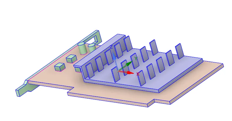
After importing the geometry we have to share the topology where we have to the do the confirmal meshing.
Now, the second phase of this project is to go the meshing and apply the name to the different parts of the components for Boundary Conditions.
After applying the naming for the material and boundary conditions, applying the mesh for it as element size 1.6mm.
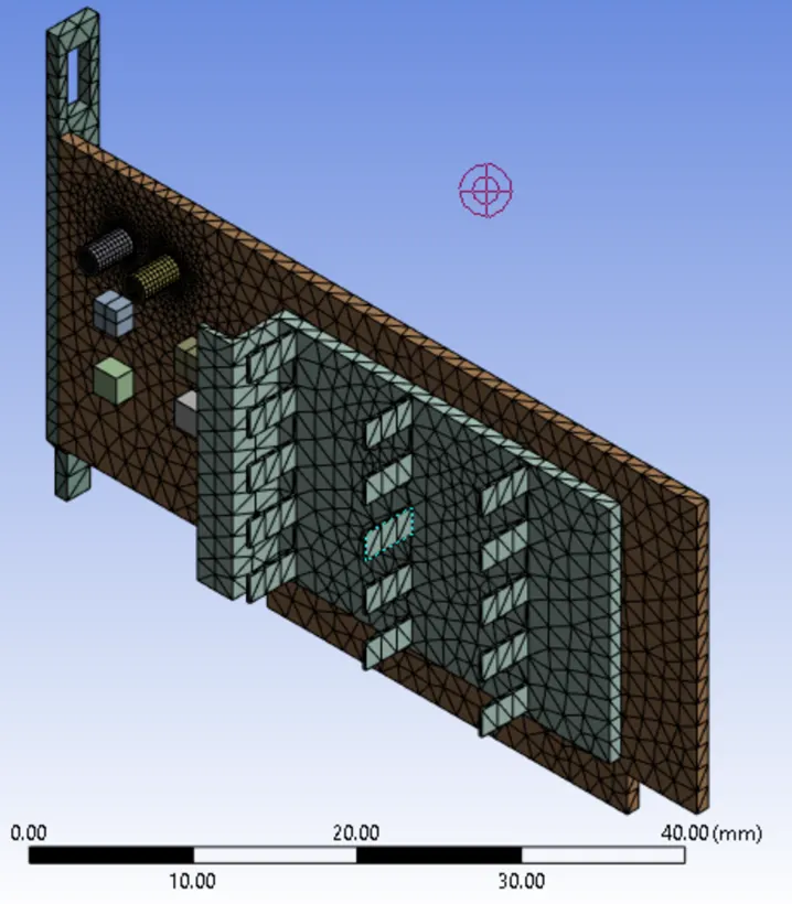
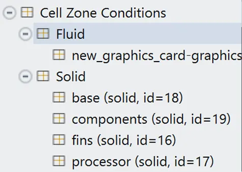
After applying the name we have to seperate the fluid component and solid component as shown in the figure:
Now taking the material for the Solids:
Base= Wood
Components= Titanium
Fins= Aluminium
Processor= Copper
Now simulating this in K-epsilon model and putting the source in processor for generating the heat in it.
Case 1: Velocity with 1m/s
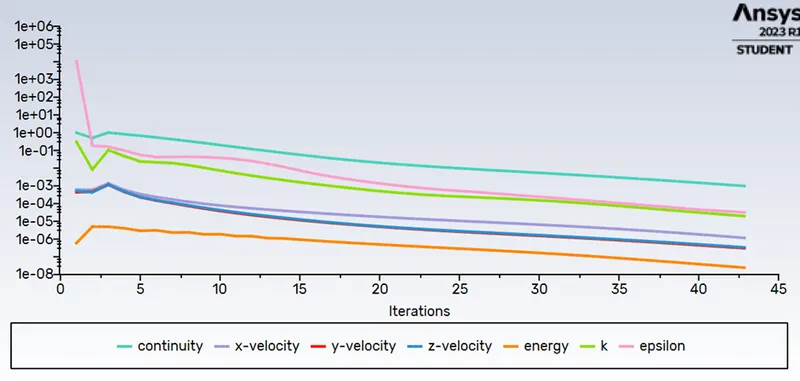
In this case we are taking the inlet velocity as 1 m/s and intializing it and the running for the calculations. It get converged at 43 iterations only as shown in the contour and residual below:
Residual:
Contour of graphic card with temperature:
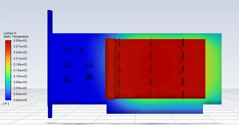
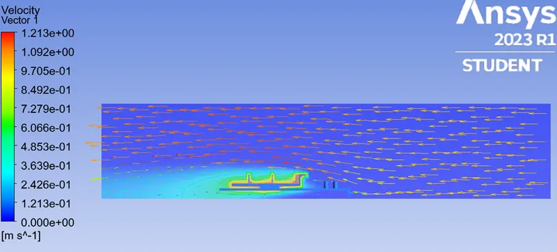
Contour of the graphic card when it is enclosed: we can observe the flow flowing form right direction to left direction as form right side it is inlet and form left sode it outlet.
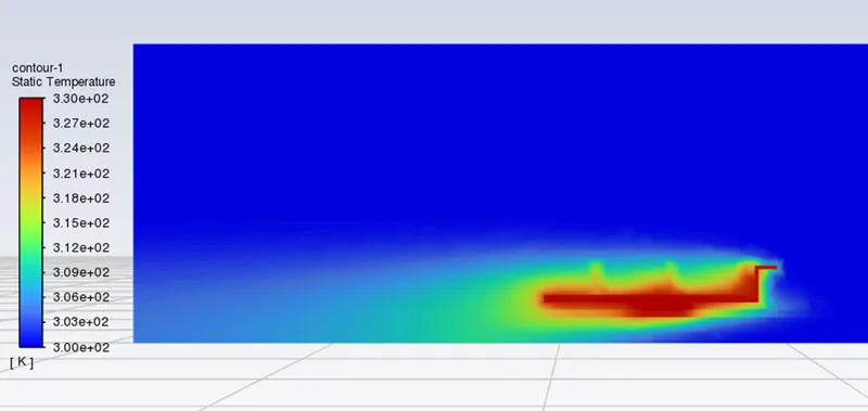
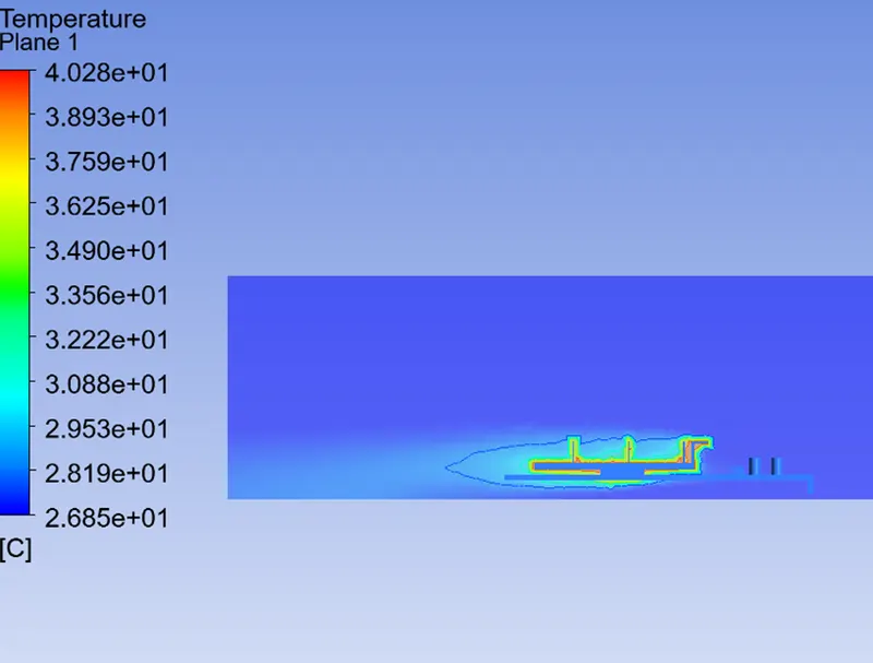
The velocity contour with temperature in it: As the fluid flows form inlet to outlet the temperaure of air gets increased due the presence of heat in the graphic card.
The temperature contour for the flow of heat:
After solving with velocity 1 m/s now with 3 m/s
Case 2: Velocity with 3m/s
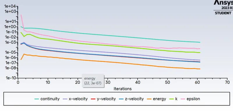
In this case we are taking the inlet velocity as 3 m/s and intializing it and the running for the calculations. It get converged at 69 iterations only as shown in the contour and residual below:
Residual:
Contour of graphic card with temperature:
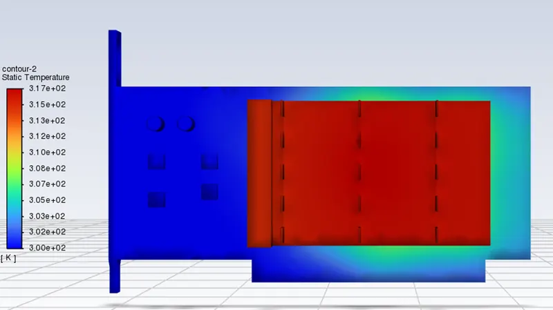
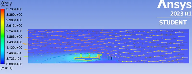
Contour of the graphic card when it is enclosed: we can observe the flow flowing form right direction to left direction as form right side it is inlet and form left sode it outlet.
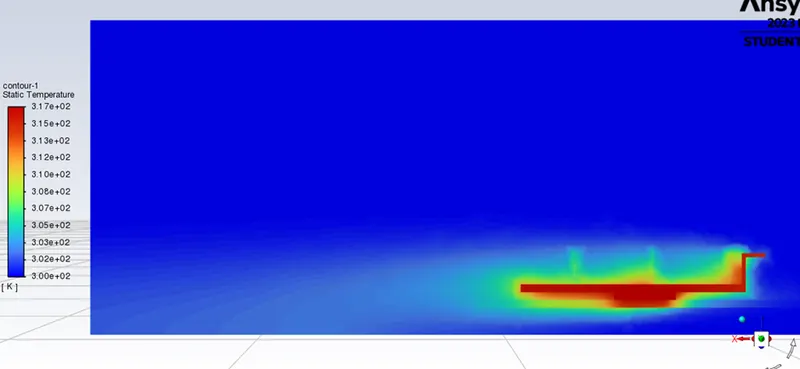
The velocity contour with temperature in it: As the fluid flows form inlet to outlet the temperaure of air gets increased due the presence of heat in the graphic card.
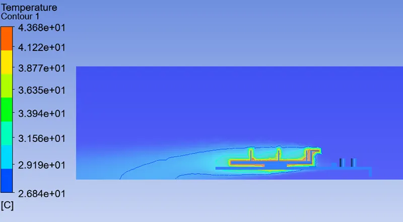
The temperature contour for the flow of heat:
After solving with velocity 3 m/s now with 5 m/s
Case 3: Velocity with 5m/s
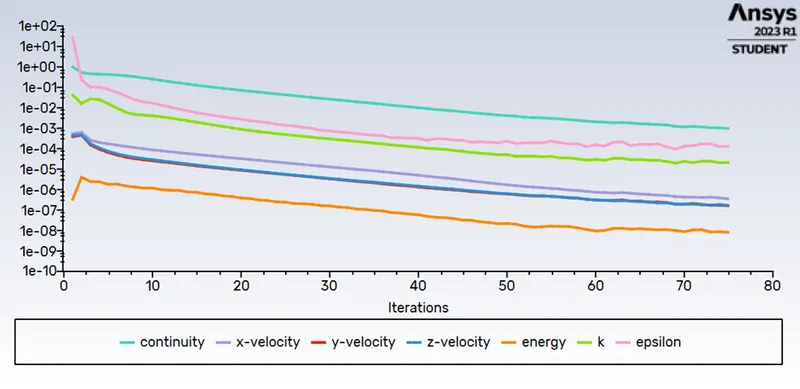
In this case we are taking the inlet velocity as 5 m/s and intializing it and the running for the calculations. It get converged at 75 iterations only as shown in the contour and residual below:
Residual:
Contour of graphic card with temperature:
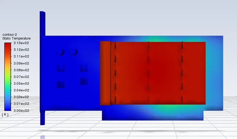
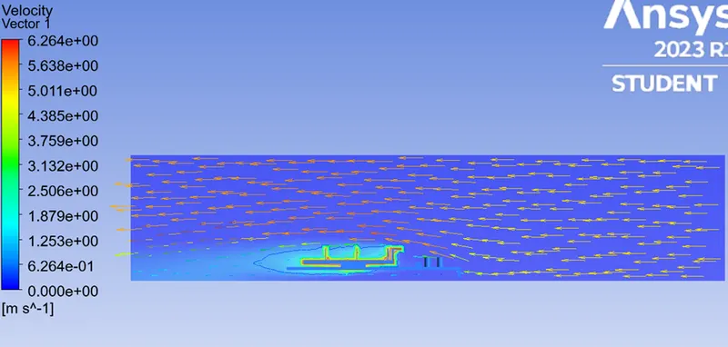
Contour of the graphic card when it is enclosed: we can observe the flow flowing form right direction to left direction as form right side it is inlet and form left sode it outlet.
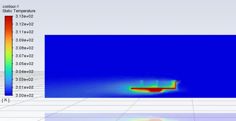
The velocity contour with temperature in it: As the fluid flows form inlet to outlet the temperaure of air gets increased due the presence of heat in the graphic card.
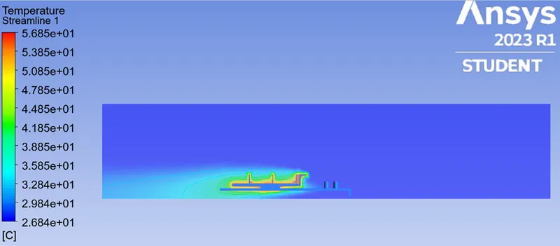
The temperature contour for the flow of heat:
From the above 3 cases we can comapare the Heat Transfer coefficent and Maximum Temparature.
| Cases | Air velocity (m/s) |
Maximum Temperature |
Average Surface Heat Transfer Coefficient `(W)/(m^2k)` |
Minimum Surface Heat Transfer Coefficient (`(W)/(m^2k)`) |
Maximum Surface Heat Transfer Coefficien(`(W)/(m^2k)`) |
| Case 1 | 1 | 446.174 | 19.235 | 0.0657 | 201.314 |
| Case 2 | 3 | 371.927 | 41.19 | 0.3512 | 234.69 |
| Case 3 | 5 | 352.783 | 57.662 | 0.4883 | 362.754 |
- In this study, the processor of the graphics card is responsible for the heat generation in the system and Fins (made of high thermal conducting materials) are used as an extended surface to dissipate heat from the processor.
- In this case, the mode of heat transfer is purely conduction. That is the reason to choose high thermal conducting material to extract/conduct heat as much as possible.
- The base of the processor is made up of an insulating material that has inherent thermal resistance (inverse of thermal conductivity). It curbs the thermal dissipation from the processor to the base, which increases thermal stress on the processor. To negate this cause, the heat dissipation needs to be enhanced from the processor walls
- The problem can be facilitated by introducing high thermal conducting material instead of insulating one. But this will cause the other components on the PCB to conduct heat and will lead to system deterioration. That is the reason to use thermal resistant material which curbs the heat transfer to adjacent circuits or components.
- In order to enhance heat dissipation from the processor walls, it requires forced air circulation and fins to extract more and more heat from the processor and dissipate it to the surrounding.
- The heat dissipation from the processor is dependent on air velocity.
- Air at different velocities has a significant impact on heat dissipation. Initially, air at low velocity is passed over the graphic card to absorb heat from the heated surfaces.
- The resulted heat transfer coefficient is also very less which indicates poor convective heat dissipation.
- However, as the velocity is increased there is further improvement in the convective heat dissipation and the reduced wall temperature. This is because the heat transfer coefficient directly varies with the Reynolds number.
- Accordingly, for higher heat transfer coefficients the heat dissipation increases proportionally
- Also heat transfer coefficient is comparatively maximum on fins than the processor walls.
- This is because much of the air is coming in contact with the fins (large extended surface area) as compared to processor walls which leads to more heat dissipation from the fins surface.[3]
Conclusion:-
- We conducted numerical simulations for heat transfer performance on the graphic card and observe the result on different Air velocities.
- The heat transfer coefficient is proportional to the air velocity, the higher the air velocity the higher the rate of heat transfer
- The results also show that the bigger surface area leads to a higher rate of heat transfer.
- So the Heat transfer coefficient is greater on fins compare to the processor.
References:
[2]:https://www.akshatblog.com/graphics-card-components-explained-in-detail/
[3]:Week 6 - CHT Analysis on a Graphics card (skill-lync.com)