Week 8 - Simulation of a backward facing step in OpenFOAM
Simulation in backward facing step:
In the given challenge we are going to simulate an incompressible-laminar-viscous flow through backward facing step geometry by performing a transient simulation.
Objective:
- Open openFoam tutorials and find the the solver to solve incompressible-laminar-viscous flow problem.
- Next step is to copy required file in solver and paste it in OpenFOAM run folder so that the official file of OpenFoam remain untouched.
- Find out block mesh script file to create domain space and provide mesh specification.
- Find ‘controlDict’ file to edit start and end time for simulation.
- In initial folder ‘0’ edit initial parameter for velocity and pressure according to faces of the given domain.
- Use blockMesh command to generate mesh and checkMesh to verify it.
- Open simulation file in paraView and plot the velocity profile at point 0.085m from inlet.
- Repeat above procedure for grading factor 0.2 to check the differences in results.
- Writing a detailed report explaining all the command and codes used in project.
Problem Statement:-
simulate an incompressible-laminar-viscous flow through the backward facing step geometry.
perform 2 case studies as described below and compare the results.
Case 1 - Simulate the flow without using any grading factor (i.e., GF = 1)
Case 2 - Simulate the flow with grading factor of 0.2. The cells should be finer near the walls (includig the step wall).
Mesh specification:-
- Number of cells along the x direction (longer dimension) = 200
- Number of cells along the longer y direction = 20;
Boundary conditions specifications:
The Boundary conditions specifications are provided in the figure.
Case I - Simulate the flow without using any grading factor (i.e., GF = 1)
Now, creating the folder in the Ubuntu via OpenFOAM tutorial named cavity_Rishi by the help of the terminal. After creating the folder or directory named cavity_Rishi opening the file and chainging the values in the blockMeshDict and the ControlDict.

After, opening the blockMeshDict file changing the values as per requirement in the file as given below:
FoamFile
{
    format      ascii;
    class       dictionary;
    object      blockMeshDict;
}
// * * * * * * * * * * * * * * * * * * * * * * * * * * * * * * * * * * * * * //

convertToMeters 1;

vertices
(
    (0 0 0)            //0
    (0.08 0 0)         //1
    (0.08 0.005 0)     //2
    (0 0.005 0)        //3
    (0.08 0.01 0)      //4
    (0 0.01 0)         //5
    (0.20 0.01 0)      //6
    (0.20 0.005 0)     //7
    (0.20 0 0)         //8
    (0.20 -0.01 0)     //9
    (0.08 -0.01 0)    //10
    (0 0 0.1)         //11
    (0.08 0 0.1)      //12
    (0.08 0.005 0.1)  //13
    (0 0.005 0.1)     //14
    (0.08 0.01 0.1)   //15
    (0 0.01 0.1)      //16
    (0.20 0.01 0.1)   //17
    (0.20 0.005 0.1)  //18
    (0.20 0 0.1)      //19
    (0.20 -0.01 0.1)  //20
    (0.08 -0.01 0.1)  //21
);

blocks
(
    hex (0 1 2 3 11 12 13 14) (80 10 1) simpleGrading (1 1 1)   //Block1
    hex (3 2 4 5 14 13 15 16) (80 10 1) simpleGrading (1 1 1)   //Block2
    hex (2 7 6 4 13 18 17 15) (120 10 1) simpleGrading (1 1 1)  //Block3
    hex (1 8 7 2 12 19 18 13) (120 10 1) simpleGrading (1 1 1)  //Block4
    hex (10 9 8 1 21 20 19 12) (120 20 1) simpleGrading (1 1 1) //Block5
);

edges
(
);

boundary
(
    inlet
    {
        type wall;
        faces
        (
            (0 11 14 3)
            (3 14 16 5)
        );
    }
    outlet
    {
        type wall;
        faces
        (
            (9 8 19 20)
            (8 7 18 19)
            (7 6 17 18)
        );
    }
    fixedWall
    {
        type wall;
        faces
        (
            (4 5 16 15)
            (4 15 17 6)
            (0 1 12 11)
            (9 20 21 10)
            (1 10 21 12)
        );
    }
    frontAndBack
    {
        type empty;
        faces
        (
            (0 3 2 1)
            (11 12 13 14)
            (3 5 4 2)
            (13 15 16 14)
            (2 4 6 7)
            (13 18 17 15)
            (1 2 7 8)
            (12 19 18 13)
            (10 1 8 9)
            (21 20 19 12)
        );
    }
);

mergePatchPairs
(

);


(
);
// ************************************************************************* //
We are changing the vertices of the given figure based on assumption of the structure which is figured down.
Geometry Creation:
Let us consider creating the geometry using 5 blocks as shown in the figure below,
NOTE: We have demonstrated the geometry creation using 5 blocks and have indexed the vertices this way. This can be varied, according to your comfort.
The Isometric View,
Now let’s, start indexing the Vertices on the Back side of the Blocks, Since openFoam uses C++ programming, we start the index from “0”. (The Numbering of the vertices can be varied according to your comfort)
Similarly, the indexing for the frontside of the Blocks are,
To View the Bigger Picture,
Finally, to define the blocks, we need to specify the right order of vertex indices
For example:
to create the 1st Block for this case,
hex (0 1 2 3 11 12 13 14) (1 1 1) simpleGrading (1 1 1)
Similarly proceed by defining the vertices of the other blocks in the Geometry.
To View geometry that you have created, clear out all the entries inside the boundary section of the blockMeshDict file and execute the blockMesh command in the terminal.
Now open paraview and view the geometry that you have created.
Meshing:
Now to mesh the geometry fill in the number of cells in x, y and z direction inside the second parenthesis of the Hex command,
i.e., hex(0 1 2 3 11 12 13 14) (10 10 1) simplegrading(1 1 1).
since this is a 2D problem, increasing the number of cells in the z direction, doesn’t make sense. To view the mesh in paraFoam, select the surface with edges option and view the mesh.
Similarly to refine the mesh near the walls of the geometry, you need to play around with the numbers in the third parenthesis. We leave that for you to figure out, how It can be done.
Boundary Conditions:
Before we run the simulations, we need to specify the initial and boundary conditions.
The given boundary conditions are,
1.Inlet: (Type patch)
The faces that contribute to inlet boundary are shown above. If we are looking at these faces from the outside, the definition of inlet boundary will be in counter-clockwise direction,
(0 11 14 3)
(3 14 16 5)
2.Outlet: (Type patch)
Similarly, we have 3 faces contributing to the outlet boundary condition. Since we are viewing the faces from outside, hence the definition of the outlet boundary will be in counter-clockwise direction,
(9 8 19 20)
(8 7 18 19)
(7 6 17 18)
Now for the other boundary look at the images below and repeat the steps to define the boundaries.
3.Front & Back: (Type empty)
4.No Slip walls: (Type wall)
After defining the boundaries correctly, to check if you have given defined them correctly, execute the blockMesh command in the terminal.Now open paraFoam, select all the patches and click apply. You will now be able to see the boundary conditions that have been applied to the geometry.
After creating the geometry and changing the dimensions of the geometry now we are going to open the controlDict file and make the required changes. We are opening the controlDict file as shown in the figure.

We are making the changes in the file based upon the time interval.
FoamFile
{
    format      ascii;
    class       dictionary;
    location    "system";
    object      controlDict;
}
// * * * * * * * * * * * * * * * * * * * * * * * * * * * * * * * * * * * * * //

application     icoFoam;

startFrom       startTime;

startTime       0;

stopAt          endTime;

endTime         0.5;

deltaT          1e-3;

writeControl    timeStep;

writeInterval   20;

purgeWrite      0;

writeFormat     ascii;

writePrecision  6;

writeCompression off;

timeFormat      general;

timePrecision   6;

runTimeModifiable true;


// ************************************************************************* //
Afer the changing values in the controlDict file we change the values of velocity and pressure as peer the requirement in the model.
To change the values of the velocity and pressure we have to go the cavity_Rishi file and open the 0 folder where we will get the "p" and "u" folder, by opening one of the folder in it and changing the values.


After opening the "p" and "U" directories, change the values in it as shown below:-
For pressure folder "p":
FoamFile
{
    format      ascii;
    class       volScalarField;
    object      p;
}
// * * * * * * * * * * * * * * * * * * * * * * * * * * * * * * * * * * * * * //

dimensions      [0 2 -2 0 0 0 0];

internalField   uniform 0;

boundaryField
{
    inlet
    {
        type            zeroGradient;
    }

    outlet
    {
        type            fixedValue;
        value           uniform 0;
    }

    fixedWall
    {
        type            zeroGradient;
    }

    frontAndBack
    {
        type            empty;
    }
}

// ************************************************************************* //
For the velocity folder "U":-
\*---------------------------------------------------------------------------*/
FoamFile
{
    format      ascii;
    class       volVectorField;
    object      U;
}
// * * * * * * * * * * * * * * * * * * * * * * * * * * * * * * * * * * * * * //

dimensions      [0 1 -1 0 0 0 0];

internalField   uniform (0 0 0);

boundaryField
{
    inlet
    {
        type            fixedValue;
        value           uniform (0.5 0 0);
    }

    outlet
    {
        type            zeroGradient;
    }

    fixedWall
    {
        type            noSlip;
    }

    frontAndBack
    {
        type            empty;
    }
}

// ************************************************************************* //
Now, after changing the values of all the inputs opening the paraview form from the terminal by typing the paraFoam and getting the physical geometry of the dimensions.
Before entering to the paraFoam we check the mesh and when its ok then only we enter it. To check the mesh we enter checkMesh as shown below:
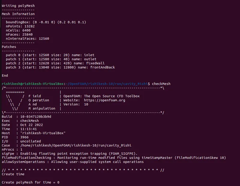
After entering it if we get the "ok" as shown below we can then go to icoFoam to check the incompressible laminar flow interval.
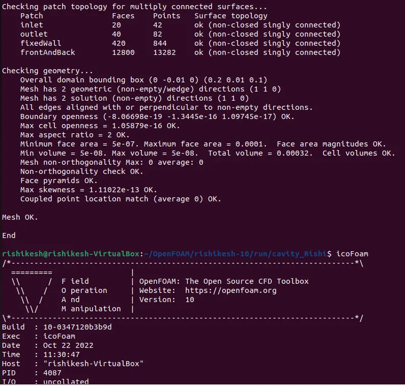
After getting the time interval we can go to the paraFoam command to open the paraview.
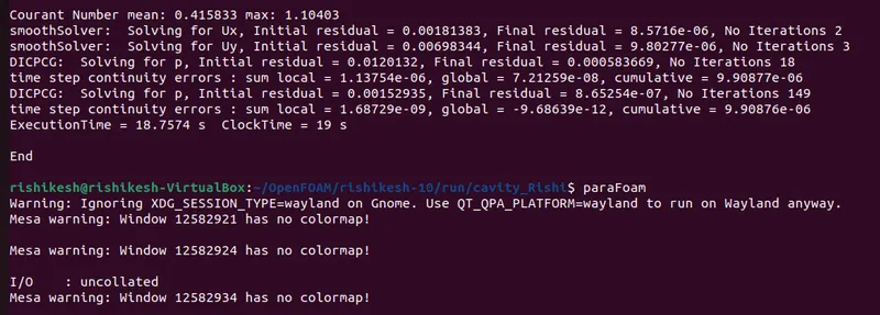
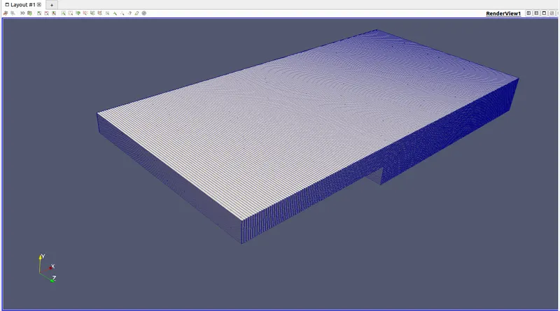
Now we can get the design in the Meshing form from the paraview.
Getting the mesh without a grid as per the dimensions mention in the command
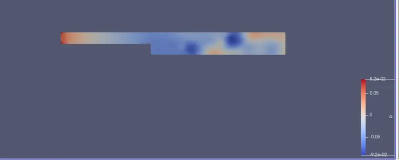
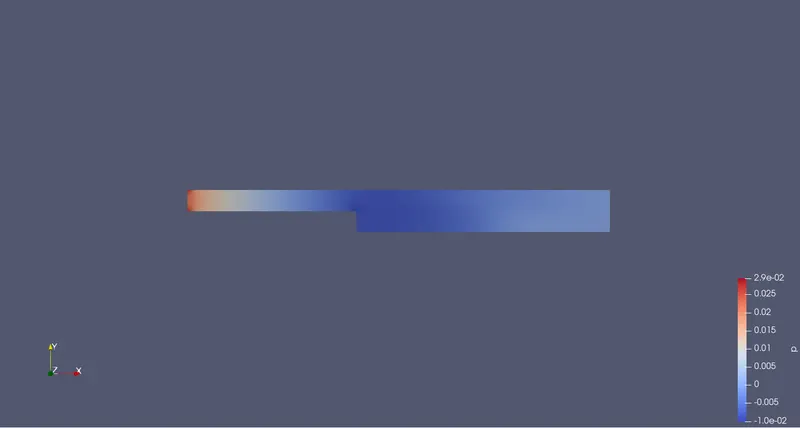
Now getting the contour of the pressure in the structure:
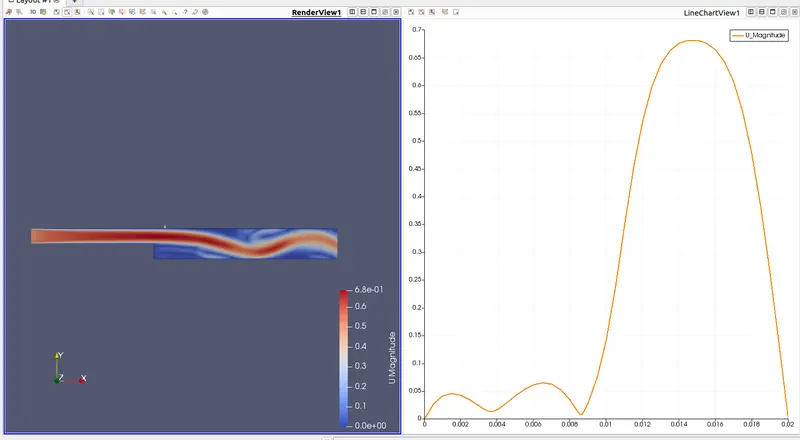
Now getting the contour and profile of the velocity of structure:
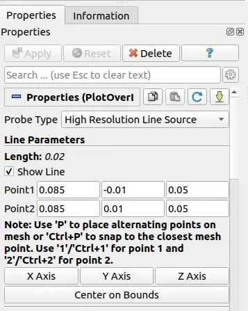
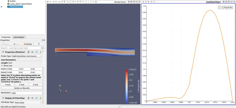
To calculate the velocity at a distance 0.085 from inlet modify the following parametres.
Now the Case II: Simulate the flow with grading factor of 0.2. The cells should be finer near the walls (includig the step wall).
Now by creating a new folder and a new blockMeshdict file with previous dimensions and putting grading factor 0.2 in it as shown below:
*---------------------------------------------------------------------------*/
FoamFile
{
    format      ascii;
    class       dictionary;
    object      blockMeshDict;
}
// * * * * * * * * * * * * * * * * * * * * * * * * * * * * * * * * * * * * * //

convertToMeters 1;

vertices
(
    (0 0 0)            //0
    (0.08 0 0)         //1
    (0.08 0.005 0)     //2
    (0 0.005 0)        //3
    (0.08 0.01 0)      //4
    (0 0.01 0)         //5
    (0.20 0.01 0)      //6
    (0.20 0.005 0)     //7
    (0.20 0 0)         //8
    (0.20 -0.01 0)     //9
    (0.08 -0.01 0)    //10
    (0 0 0.1)         //11
    (0.08 0 0.1)      //12
    (0.08 0.005 0.1)  //13
    (0 0.005 0.1)     //14
    (0.08 0.01 0.1)   //15
    (0 0.01 0.1)      //16
    (0.20 0.01 0.1)   //17
    (0.20 0.005 0.1)  //18
    (0.20 0 0.1)      //19
    (0.20 -0.01 0.1)  //20
    (0.08 -0.01 0.1)  //21
);

blocks
(
    hex (0 1 2 3 11 12 13 14) (80 10 1) simpleGrading (0.2 5 1)   //Block1
    hex (3 2 4 5 14 13 15 16) (80 10 1) simpleGrading (0.2 0.2 1)   //Block2
    hex (2 7 6 4 13 18 17 15) (120 10 1) simpleGrading (5 0.2 1)  //Block3
    hex (1 8 7 2 12 19 18 13) (120 10 1) simpleGrading (5 5 1)  //Block4
    hex (10 9 8 1 21 20 19 12) (120 20 1) simpleGrading (5 5 1) //Block5
);

edges
(
);

boundary
(
    inlet
    {
        type wall;
        faces
        (
            (0 11 14 3)
            (3 14 16 5)
        );
    }
    outlet
    {
        type wall;
        faces
        (
            (9 8 19 20)
            (8 7 18 19)
            (7 6 17 18)
        );
    }
    fixedWall
    {
        type wall;
        faces
        (
            (4 5 16 15)
            (4 15 17 6)
            (0 1 12 11)
            (9 20 21 10)
            (1 10 21 12)
        );
    }
    frontAndBack
    {
        type empty;
        faces
        (
            (0 3 2 1)
            (11 12 13 14)
            (3 5 4 2)
            (13 15 16 14)
            (2 4 6 7)
            (13 18 17 15)
            (1 2 7 8)
            (12 19 18 13)
            (10 1 8 9)
            (21 20 19 12)
        );
    }
);

mergePatchPairs
(

);


(
);
// ************************************************************************* //
Now changing the values in controlDict file:
FoamFile
{
    format      ascii;
    class       dictionary;
    location    "system";
    object      controlDict;
}
// * * * * * * * * * * * * * * * * * * * * * * * * * * * * * * * * * * * * * //

application     icoFoam;

startFrom       startTime;

startTime       0;

stopAt          endTime;

endTime         5;

deltaT          0.001;

writeControl    timeStep;

writeInterval   20;

purgeWrite      0;

writeFormat     ascii;

writePrecision  6;

writeCompression off;

timeFormat      general;

timePrecision   6;

runTimeModifiable true;


// ************************************************************************* //
Now changing the vlaues of pressure :
FoamFile
{
    format      ascii;
    class       volScalarField;
    object      p;
}
// * * * * * * * * * * * * * * * * * * * * * * * * * * * * * * * * * * * * * //

dimensions      [0 2 -2 0 0 0 0];

internalField   uniform 0;

boundaryField
{
    inlet
    {
        type            zeroGradient;
    }

    outlet
    {
        type            fixedValue;
        value           uniform 0;
    }

    fixedWall
    {
        type            zeroGradient;
    }

    frontAndBack
    {
        type            empty;
    }
}

// ************************************************************************* //
Now changing the values of Velocity:
FoamFile
{
    format      ascii;
    class       volVectorField;
    object      U;
}
// * * * * * * * * * * * * * * * * * * * * * * * * * * * * * * * * * * * * * //

dimensions      [0 1 -1 0 0 0 0];

internalField   uniform (0.1 0 0);

boundaryField
{
    inlet
    {
        type            fixedValue;
        value           uniform (0.2 0 0);
    }

    outlet
    {
        type            zeroGradient;
    }

    fixedWall
    {
        type            noSlip;
    }

    frontAndBack
    {
        type            empty;
    }
}

// ************************************************************************* //
Again repeating the same by clicking the blockMesh, checkMesh and icoFoam.
Now, by opening this in paraview via paraFoam.
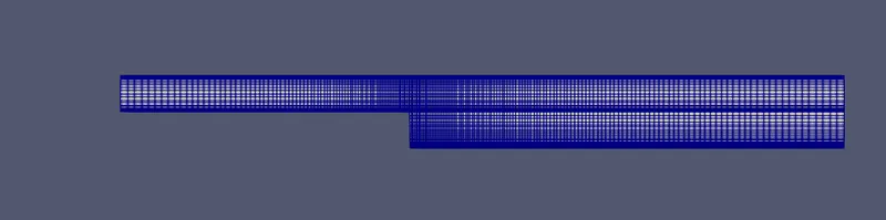
Meshing with the grading factor 0.2 is shown in the figure.
Now, Contour of the pressure:
Now the Contour and proflile of the velocity:
Conclusion:
We have done plotting velocity plot for both, without grading factor and with 0.2 grading factor, cases. If we take a look at all the three line graph, we can see, the plot for velocity without grading factor seems more smooth and accurate than other two plot. So one can say, grading can disrupt out result. But it is incorrect. Because, if we take good look at it, we can notice, the mesh is fine at step wall along the X-axis but very coarse along Y-axis. Therefore, we are not getting smooth plot for velocity at 0.085 point at Y-axis.
To understand this thing clearly, we can see the above Contours and profile where we can see- on the left side there is coarse mesh and on the right side fine mesh. There respective graphs are presented, which can really convince anyone how at any given point mesh produce a plot. With grading factor 1 mesh is giving very smooth plot except one small pick near point 0.01 and on the other hand, for coarse structured mesh, the curve of graph the curve is not smooth, there are sharp corner forming at the top of the curve.