Week 6 - CHT Analysis on a Graphics card
OBJECTIVE
- To perform conjugate heat transfer analysis on Graphics Card for different inlet velocities
- To find out the maximum temperature attained by the processor
Conjugate Heat Transfer:
Conjugate heat transfer (CHT) is a method of analysis which is used to measure the heat transfer between the body and the fluid flowing over or inside it as a result of interaction between two objects. The Conjugate Heat Transfer analysis type allows for the simulation of heat transfer between solid and fluid domains by exchanging thermal energy at the interfaces between them.
Conjugate heat transfer analysis gives a thorough understanding of the velocity distribution and fluid heat transfer mechanism, such as in engines, as well as the temperature distribution in solids and fluids.
For this challenge, the CHT analysis is used to find out the maximum temperature attained by the processor. The inlet velocities are varied and heat dissipation is observed through the fins.This is important to study as todays processors are becoming more and more powerful and as a result are generating a lot of heat. So an efficient cooling system has to be designed in order to maintain the temperature of the processor under safe levels.
PREPARING THE GEOMETRY
The model was loaded into Spaceclaim and checked. Shared topology was enabled in order to generate a common interface with diferent components of the graphics card. This allows us to create a conformal mesh.
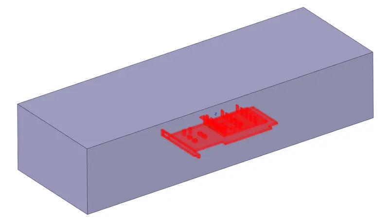
NAMED SELECTIONS-
1.BASE
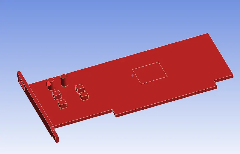
2. FINS
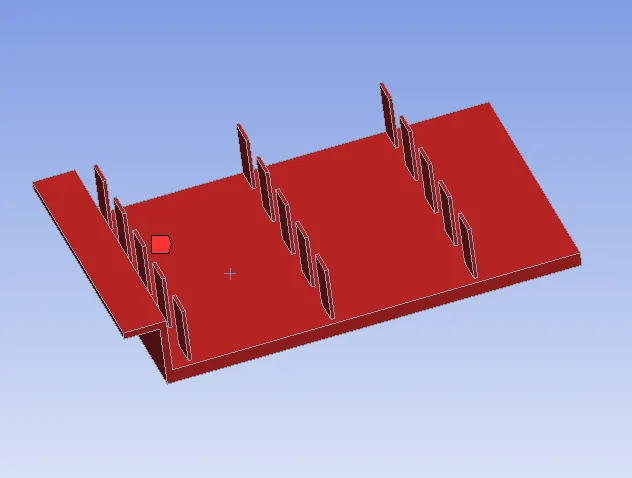
PROCESSOR

ENCLOSURE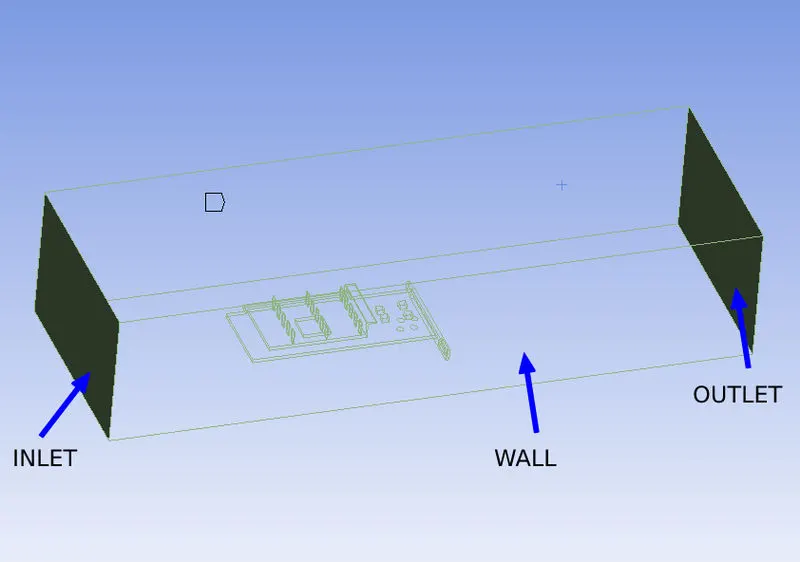
MESHING (CASE 1)
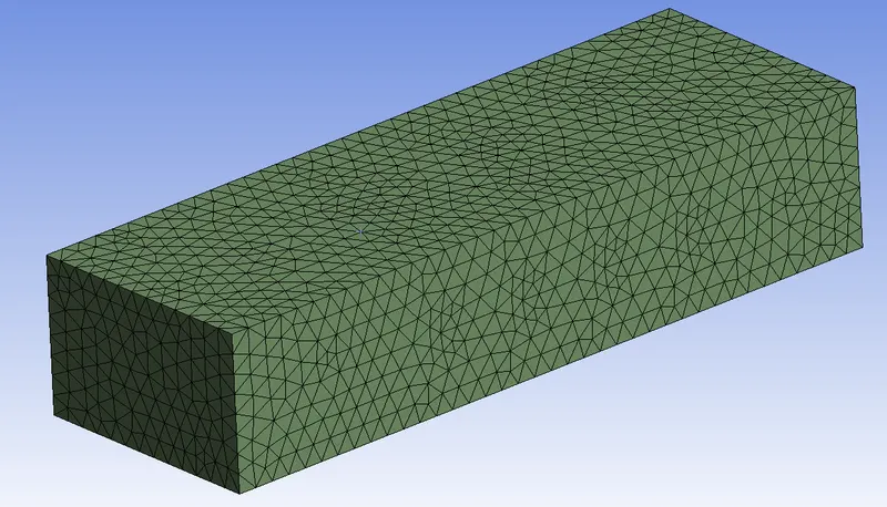
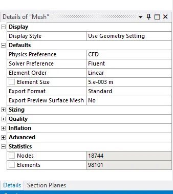
For the first case, a base mesh of 5mm was created.
SIMULATION SETUP
Solver: Steady State
Type: Pressure Based
Turbulence Model: k-Omega(SST)
Materials used-
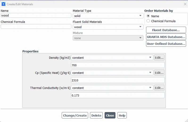
Base- Wood
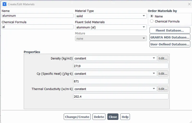
Fins - Aluminium
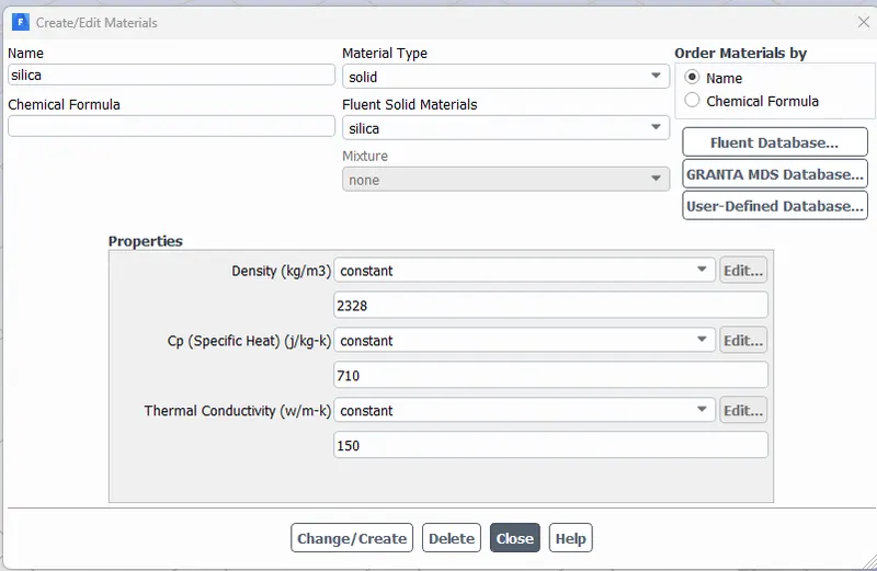
Processor - Silica
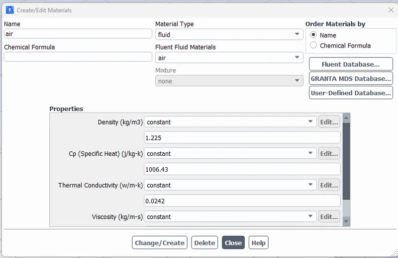
Enclosure - Air
Boundary conditions:
Inlet:
Type: Velocity Inlet
Velocity: 2 m/s
Temperature: 300 K
Outlet:
Type: Pressure Outlet
Pressure: 0 Pa(Gauge Pressure)
Temperature: 300 K
- Symmetry: Symmetry
- Wall: Wall
Cell Zone Conditions:
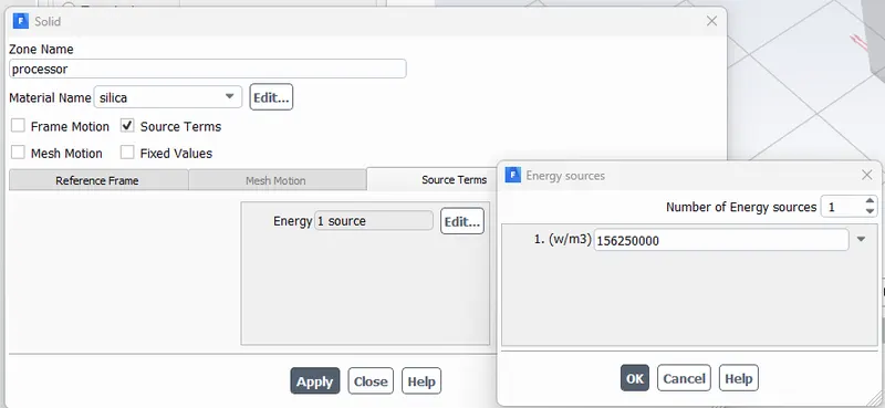
The heat source was selected as processor. In the source term tab, Energy source is selected as 1.
The heat generated by the card is calculated as below-
Power consumed is assumed as 10W
Volume of the processor - 8x8x1=64mm3 = 64e−9m3
Heat generated - P/V = 10/64e−9
= 156250000 w/m3
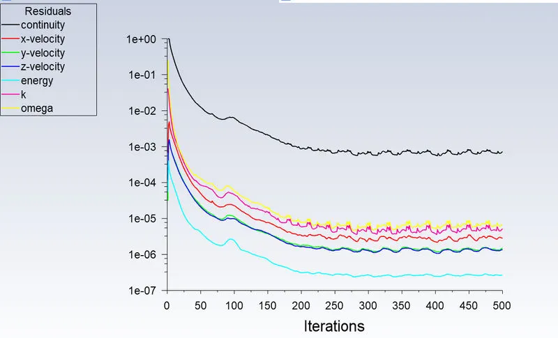
Solution (Case1):
Method- Standard
Number of Iterations - 500
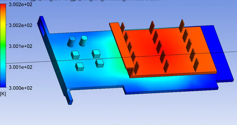
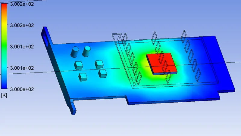
MESHING (CASE 2)
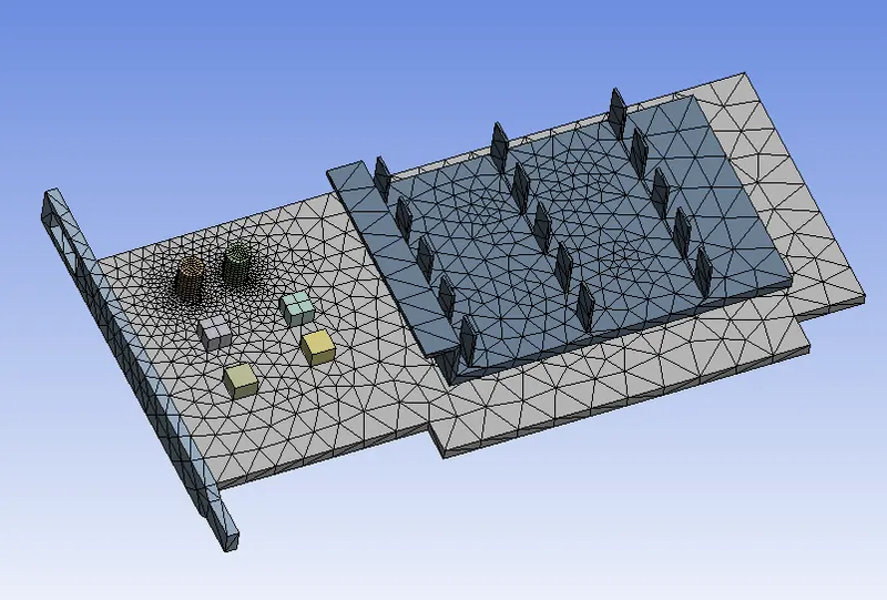
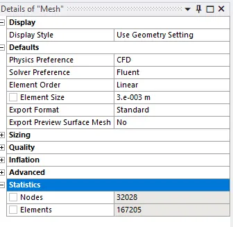
Element size - 0.003m
Body sizing:
Processor - 0.001m
Fins - 0.001m
Base - 0.003m
Boundary conditions:
All the conditions are same as case 1 except the inlet velocity whic has been changed.
Inlet:
Type: Velocity Inlet
Velocity: 3 m/s
Temperature: 300 K
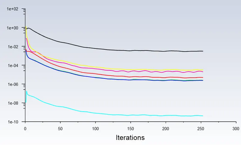
Solution (Case2):
Method- Standard
Number of Iterations - 250
MESHING (CASE 3)
Element size - 0.003m
Body sizing:
Processor - 0.0005m
Fins - 0.0005m
Base - 0.003m
Boundary conditions:
All the conditions are same as case 1 except the inlet velocity whic has been changed.
Inlet:
Type: Velocity Inlet
Velocity: 5 m/s
Temperature: 300 K
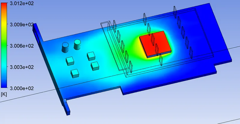
Solution (Case2):
Method- Standard
Number of Iterations - 250
RESULTS:
| Inlet Velocity of Air(m/s) | Temperature at Processor (K) | Temperature at Fins (K) |
| 2 | 16.42 | 16.36 |
| 3 | 16.40 | 16.32 |
| 5 | 16.37 | 16.34 |
CONCLUSIONS:
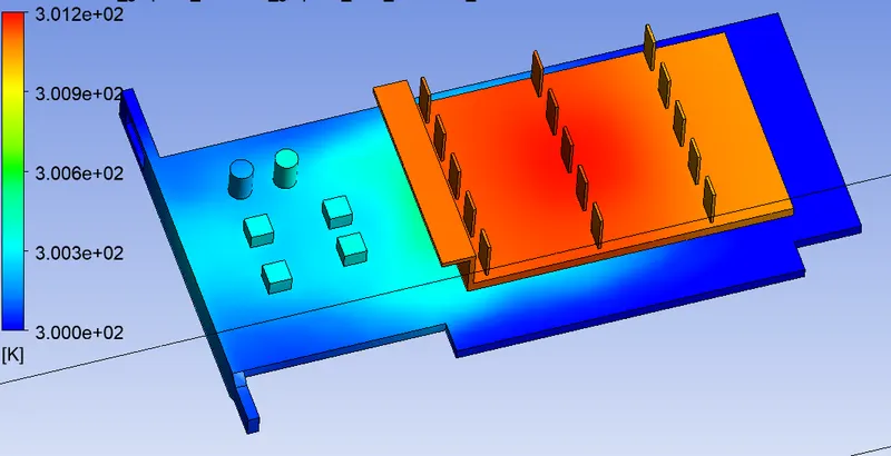
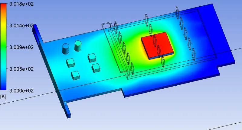
- With the decrease in mesh size and increase in the number of elements, the temperature distribution is better observed. It yields a more accurate picture of the simulation.
- From the above data represented in the table, we can clearly notice the temperature differences for different inlet velocities. The net temperature of the components tends to decrease with the increase in inlet velocities.
- Hence for better cooling and to limit the thermal throttling in graphic cards, the velocity of air needs to be increased. This increases the rate of heat transfer and helps protect the components from damage.