Week 2 Challenge : Surface meshing on a Pressure valve
First thing I did was to check the model topo. To do this I went checks and selected geometry.
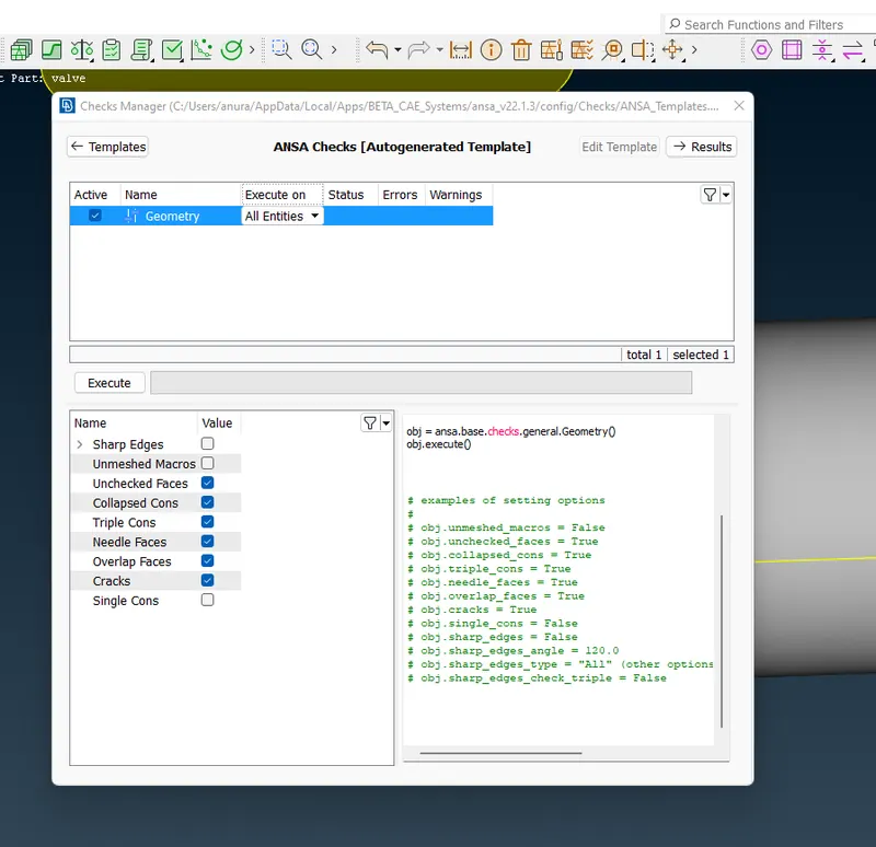
Unmeshed macros is uncheked because model is not meshed yet. Then I clicked execute. The results showed me multiple single cons are present in the model.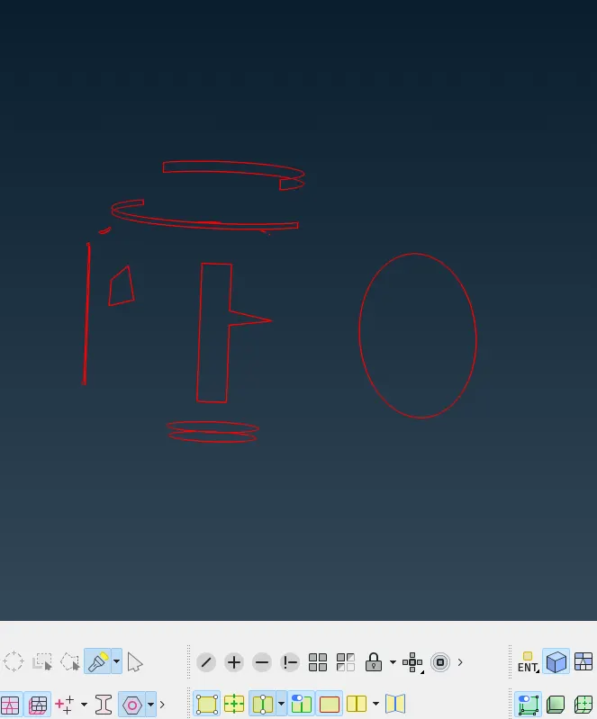
Single cons can be checked with double & triple cons turned off and holding ctrl + shift for wireframe mode.
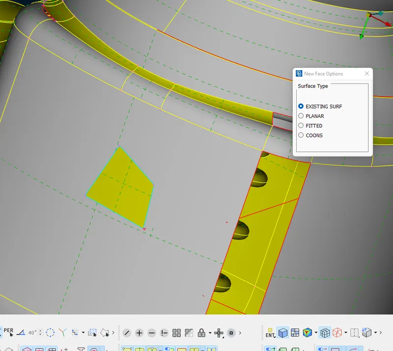
To fix these errors, I went to topo module, and in faces I selected new face option and created a new face wih surface type as existing surface.
For the next patch I selected coons options and turned on loop option.
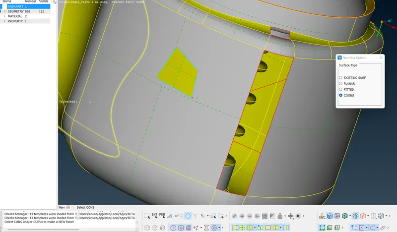
Similaly I filled the other patches with Coons with entity selection and filled all the gaps.
Next by checking in the wireframe mode, there were stll some single cons present and i needed to be solved.
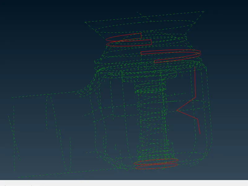
For some of the covered patches with single cons, I deleted the covered patch and deleted the existing face and then created a new face with coons.
To patch the other single cons on top and bottom, I selected 2 single cons with loop but it did not work. With entity option also its not generating correct face as the length of cons are different.
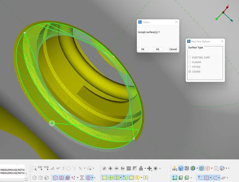
To solve this, I selected the cons with same length, and now the face is generated correctly.
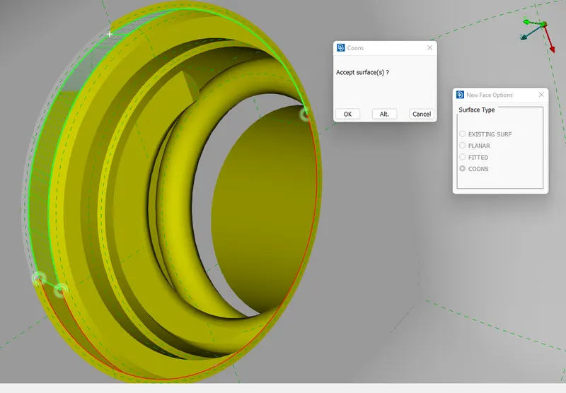
Similaly, I patched the other single cons.
The opening at the bottom of the model also needs to be closed. For that, I used fill hole to patch it.
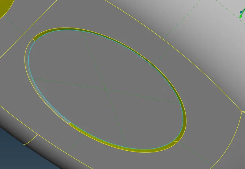
After that I again did a geometry check to check for errors. It showed that single cons are eliminated but 4 triple cons were present.
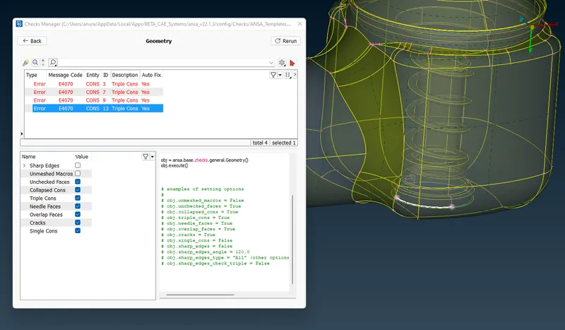
To check this, I used the INOT option to isolate the 3 surfaces.
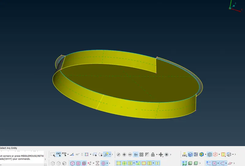
Since this suface is needed and cannot be avoided, the triple con is not considered as an error in this case. 4 triple cons are there which cannot be avoided since the model needs to closed. In this case all 3 surfaces are required.
Next I checked for errors again.I checked for single cons with perim points, double and triple cons and shadow mode turned off at the bottom and turning on wireframe mode.
Before meshing we need to check for small surfaces because if surface is smaller than mesh length, then the mesh will not generate properly. The surace should be greater than target length of the mesh. I eliminated the small surfaces by using cut option and doing right click.
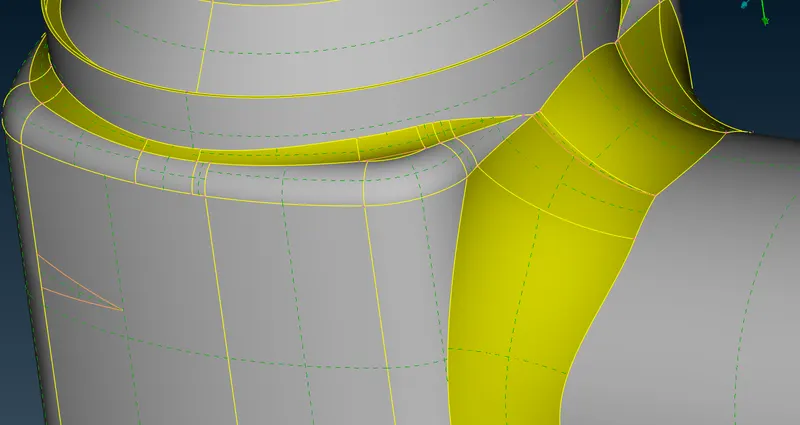
This is how I did Topology cleanup.
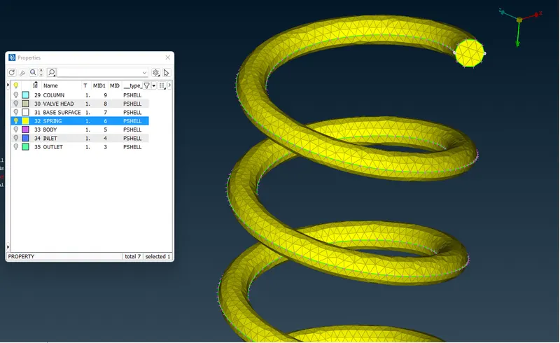
Next I needed to create and assign PIDs. I went to PID manager and created new PID for each part of the model like inlet and outlet. I gave different colors for different PID. Next step I applied PID to the different surfaces.
To assign PID to the body, I used OR boolean with PID region selected. This enables us to select only the body and not other surfaces. We can check our selection by rotating the model or in the wireframe mode.
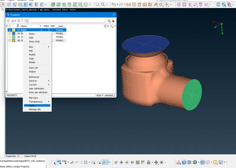
After the body is isolated then I assigned the BODY PID to the body surface. Then I created PID for the remaining parts i.e spring, valve head and base surface.
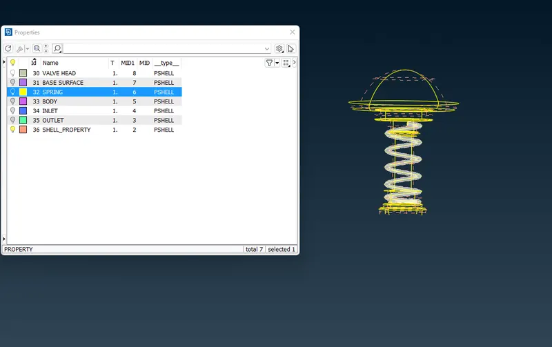
For the base surface I select using entity mode. Then I applied Spring PID by selecting using PID region option.
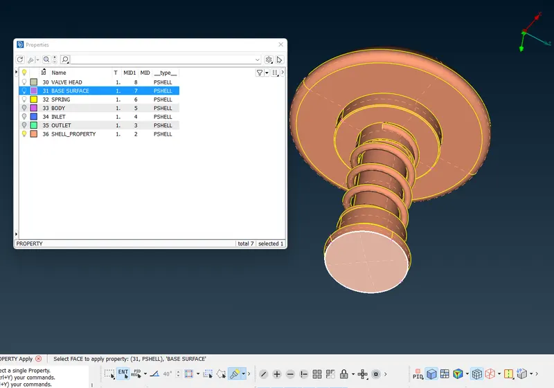
Next I had to apply PID to other innner surfaces also. But I was not able to isolate the valve head fom the column. To separate the valve head I use lock option to lock the current view. then I select the surface between the valve head and column using NOT option with entity. Now I was able to assign the PID to VALVE HEAD and other sufaces.
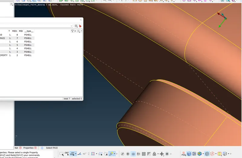
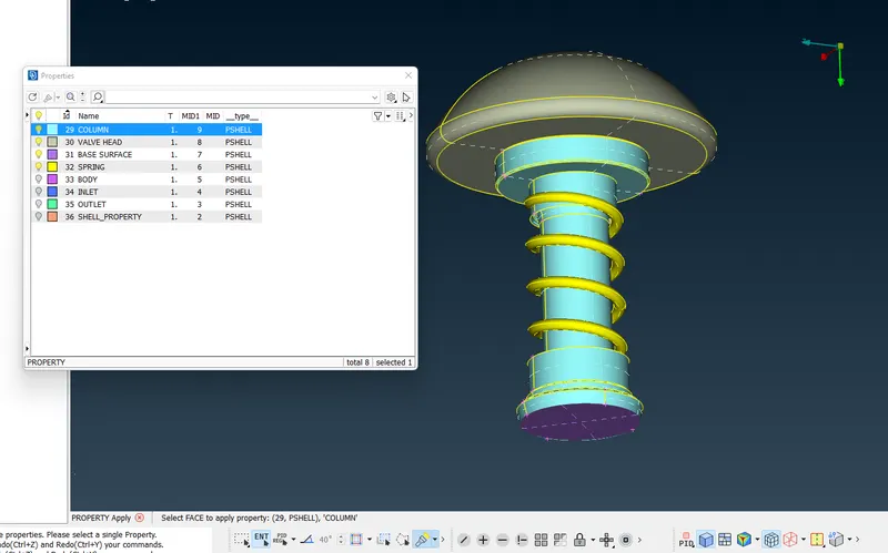
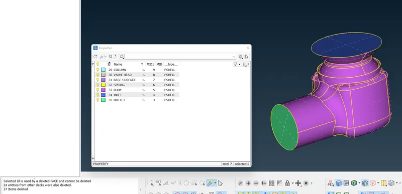
In PID manager SHELL PROPERTY PID is still present which is the surface that we have hidden to separate the valve head. So now I have to assign a PID for this surface.So I assign the Colum PID to this surface. Now the 36 SHEEL_PROPERTY Pid is empty but its not getting deleted since there is a deleted face.
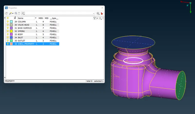
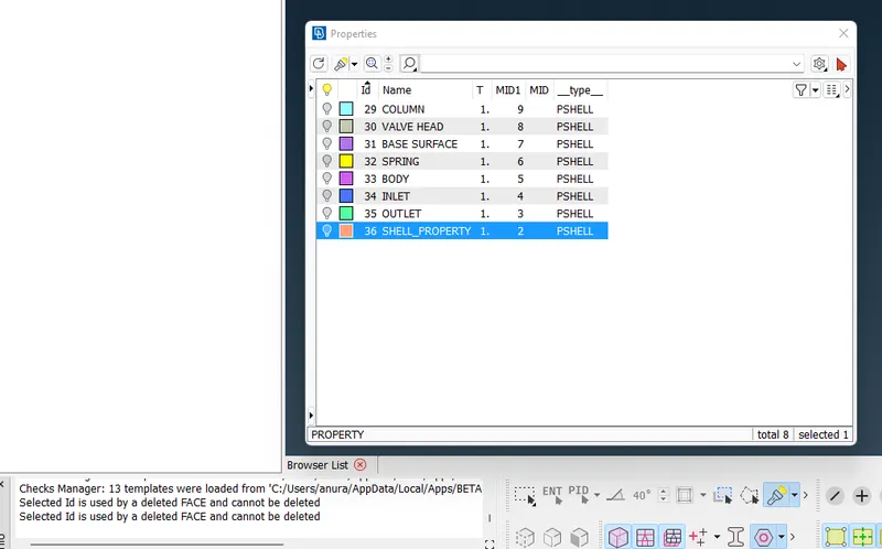
To see the deleted faces, I go to TOPO module and select undelete and it showed me all the deleted faces.
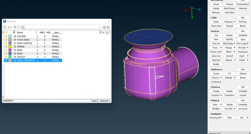
Now the face is overlapping. So now i use topo option to join the 2 faces and now it is forming a triple con. Then in PID manager i selected the SHELL PROPERTY Pid and deleted it. So now there ae no unwanted surfaces of PIDs
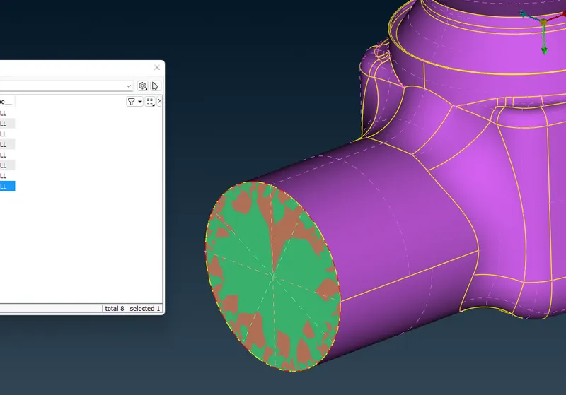
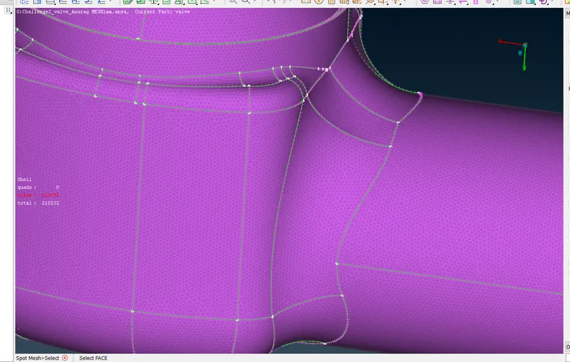
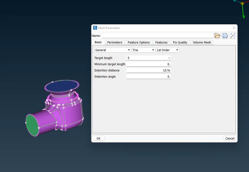
Now before meshing, I gave the mesh length as 5 and also in mesh parameters the length as 5 and in quality critera I gave max min lengt as 3 and 7. Now in mesh generation I selected spot mesh and then I mesh all the surfaces one by one.
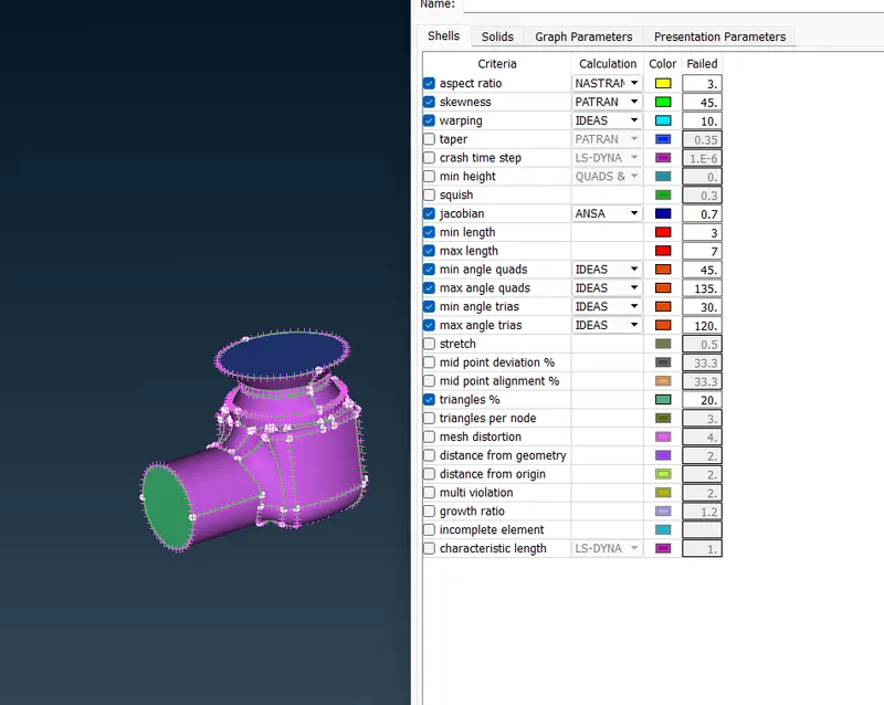
The inner surfaces were meshed after hiding the outer surfaces in the PID manager.
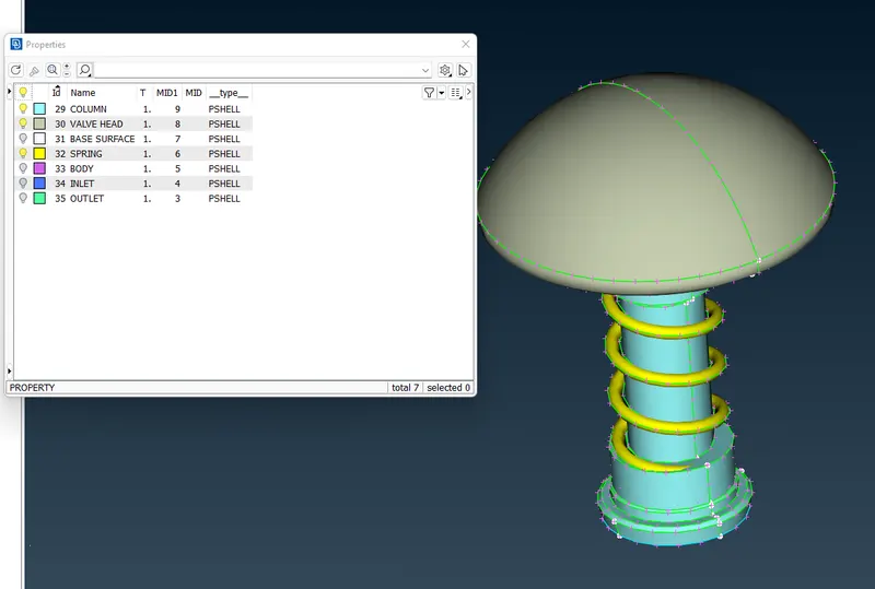
Now when the spring is meshed, it changes shape because the mesh lenght is greater than the dia of the spring. Hence we should give target length accoding to the size of the surfaces.
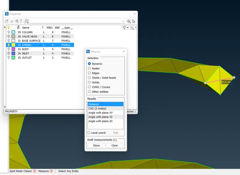
Next I created a copy of the model and gave the mesh lengh as 3. The mesh is finer and rhe shape of the model, specially the spring appears more round now. The 3mm length is giving better results than 5mm.
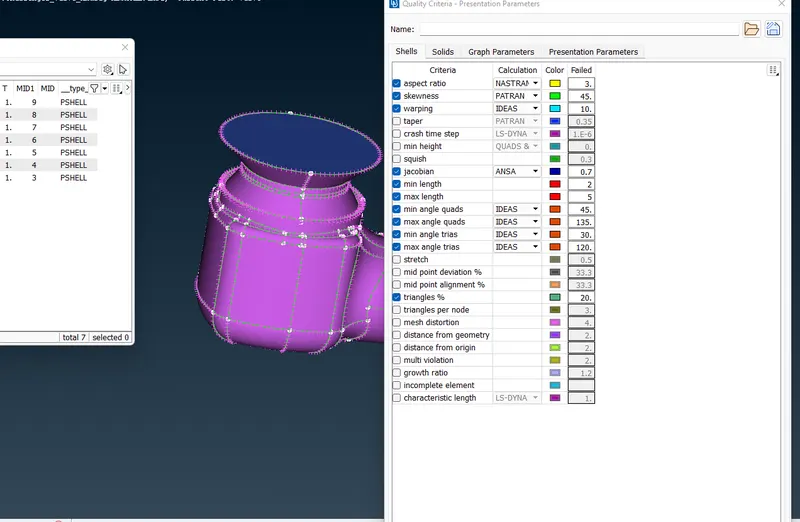
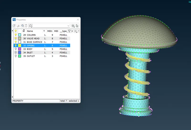
For the next model, I gave target lengh as 1mm and gave min and max length as 0.5 and 2. The model with 1mm mesh length is giving the best results.