Week 3 Challenge : CFD meshing on Turbocharger
AIM- To conduct volumteric mesh for the given turbocharger model
First I did Topo cleanup. I noticed that there are overlapped sufaces. To confim the overlap surfaces, I checked with TOPO and checked for triple cons. There are also single cons present.
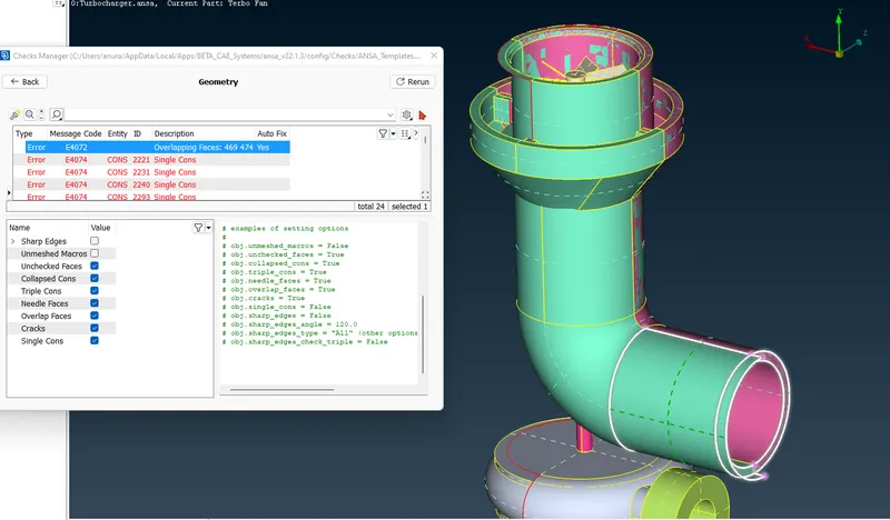
I tried to delete the unwanted faces directly by enabling PID Region then selecing the cross hatch of the surface.
For the remaining surface i hid the green surface with NOT boolean. This made the unwanted surface visible. Then I selected the unwanted surface and deleted it. Then i notices there is an over extending surface in the exhaust pipe. So i slected it with Entity and deleted it. Then I created a new surface with COONS.
Now there ae some single cons and triple cons present at the top. To delete the triple cons, I hide the surface using NOT boolean and select and delete the unwanted faces.
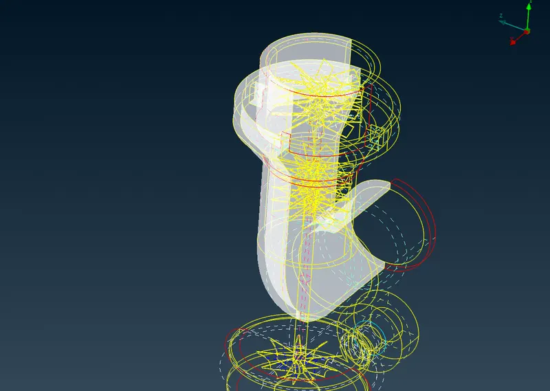
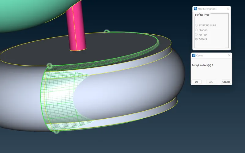
To fill the surface I selected the loop and used COONS to fill it, but its not creating the surface correctly since it is uneven.
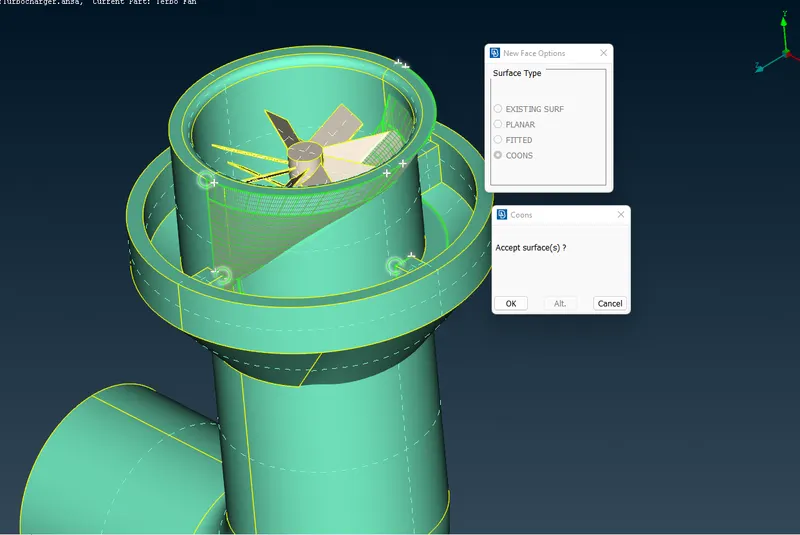
To solve this, I projected the points to the top and created multiple small surfaces. Then I used fill hole command to fill the rest of the spaces.
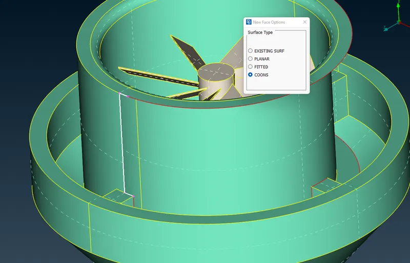
To check for any other single cons I used wieframe mode. Now there is a single con present inside the pipe which is not visible from the outside. So I hid the outside surfaces using NOT. Now there are extended surfaces passing each other.
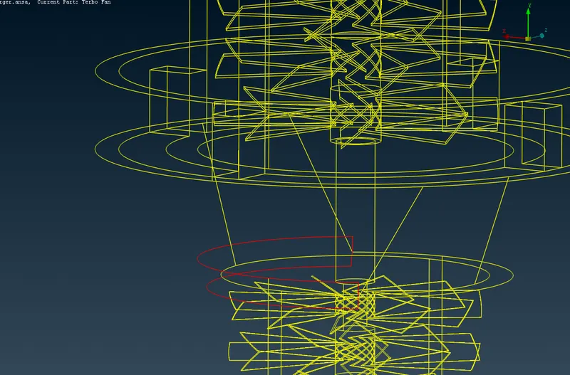
After checking in wireframe mode, This is showing as single con and not as triple cons. Now with intersect command i select the 2 sufaces. Now the surfaces become intersected. These sufaces can now be selected and deleted.
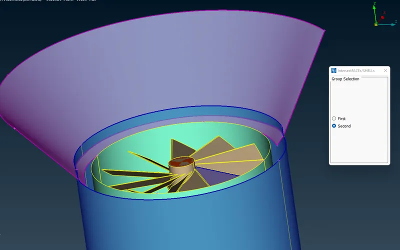
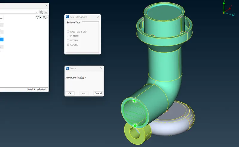
At the bottom, there is and open patch present which needs to be closed. But by selecteing the fill hole option its not generating the correct surface. Even with Coons and Fitted option the surface is not generated correctly.
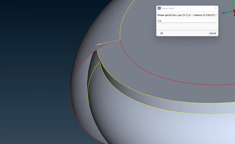
In order to solve this, I created multiple hot points in the con with parametric option with 0.5 spacing to create them exactly in the centre of the cons.The same method is repeated for the other open side as well.
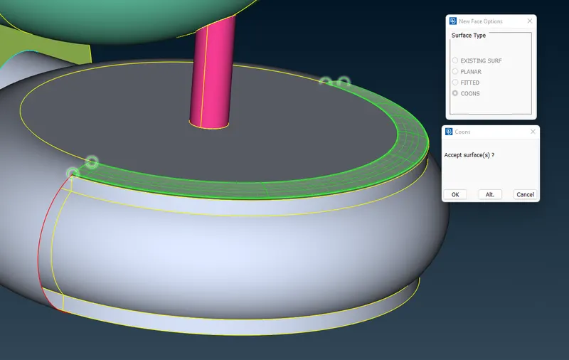
Now wih Coons option with Entity select, I created surfaces one by one.
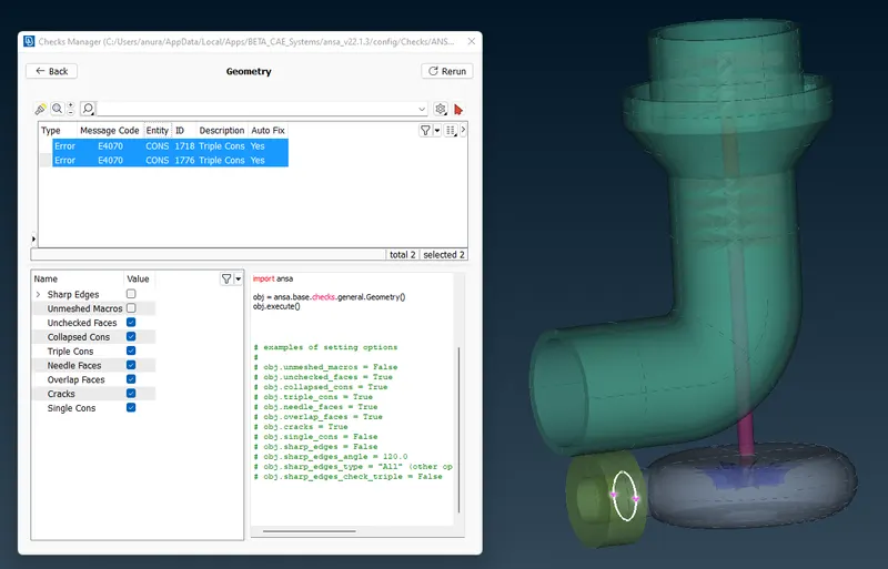
Then I performed a geometry check and it showed there is a single con present on the shaft.
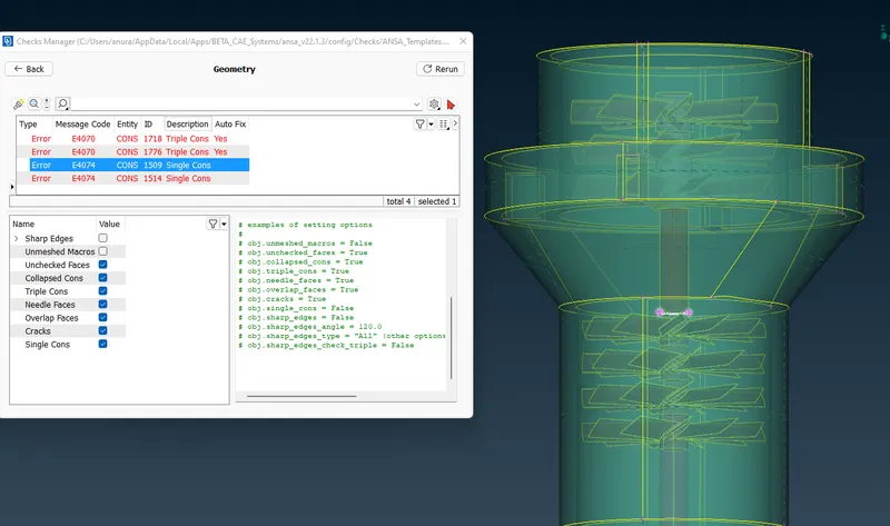
Now I isolated the surface with single and it's neighbor surface in PID manager. Then I did TOPO to merge the surfaces.Now a triple con is created in that area.
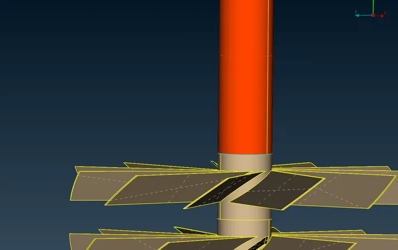
I again do the gemotery check if any single cons are present. There is no single cons but a lot of triple cons are there.I checked for the triple con near the compressor outlet. Since all the surfaces are important we cannot consier this as an error.
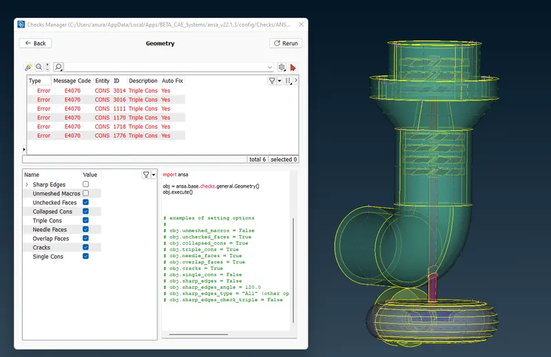
There is triple cons in the shaft with overlapping surfaces. This needs to be solved. I selected the overlaping surfaces and then deleted them one by one.
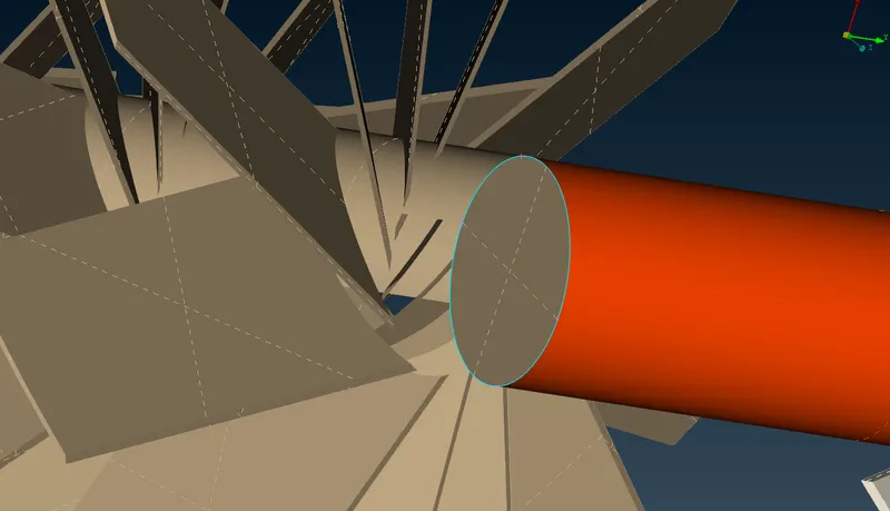
The shaft is now overlapping with the turbine hub. So to separate this, I made a cut on the shaft by projecting the cons of the blades hub.
Now the surface near the cut is not smooth. I used the fine option in the auxiliaries tab to smoth out the surface. Then I deleted the overlapped surface. Now by ddeleting all the unecessaty suraces I joined the 2 PIDs with TOPO.
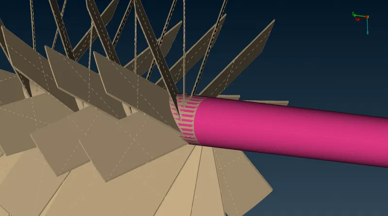
At the top of the shaft there was overlapping as well. Before deleting that surface, I projected the con on the sirface of the blades hub. Since the diameterr of the shaft and blade ub is not the same, I had to create a new surface there.
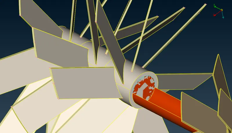
At the bottom of the shaft, there is also a triple con. But the surfaceis not having any cross hatch and it is not separated from the compressor blades. To solve this I projected the shaft cons to the surface and created the cut an deleted the suface.
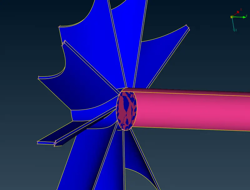
I again performed the geomtry check and it showed 2 triple cons are present but they are necessary and should not be deleted.
Before doing meshing we need to check for any pen surfaces. In the PID manager, I checked each of the PID individually for any open sufaces. In the pipe there are open spaces so I closed them.
Now I have to assign new PIDs for the new suraces. So I created new PIDs and assigned to all of them.
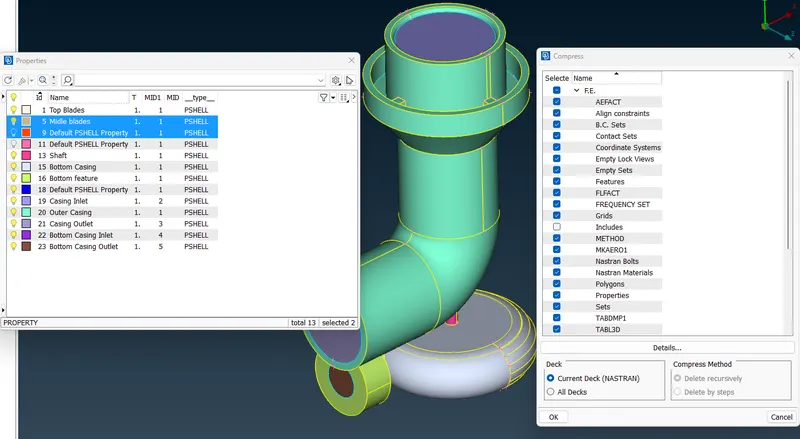
After assigning the correct PIDs to the correct parts, there are some empty PIDs. I deleted them with compress command
Now I have set target for for each PID.
Blade Stage 1 = 1mm
Blade Stage 2 = 1mm
Impeller = 2mm
Shaft rotor = 1mm
Tubo casing = 5mm
Compressor casing = 5mm
Inlet Casing Cover = 5mm
I isolated the parts with the same target length. For parts with 5mm length, i.e Turbo casing, compressor casing and inlet casing I set the mesh parameters target length as 5 ans slelectd the tria option. In quality criteria, I set the max and min length as 3 and 7. Then I selected the perimeters and macros and give it as 5. Now I meshed them one by one.
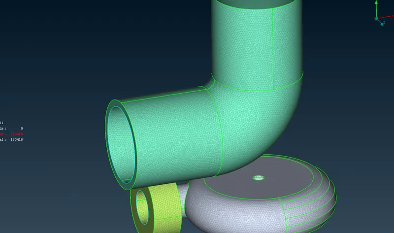
I isolated the the blades, shaft rotor and impeller. I now meshed the shaft and the blades with 1mm length. Now when I meshed the impeller with mesh length as 2mm, the mesh in the shaft was not visible.
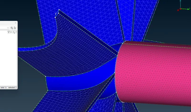
So i again meshed the shaft and then i meshed the impeller surfaces individually. I individually selected each surface of the impeller and meshed it. Now at the joining of the the shaft and impeller, the mesh size is varying.
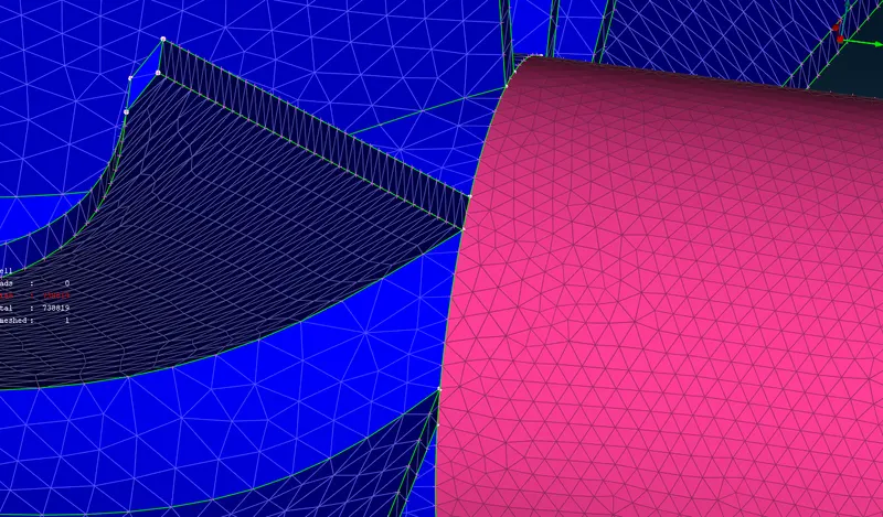
Now all the surfaces has been meshed. It was now time to do volumetric mesh.
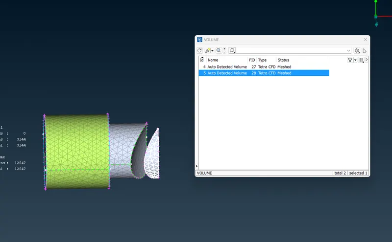
In the volumteric mesh deck, I selected define and selected auto detect. I kept the option as whole db and clicked OK. Now it is showing a list of undmeshed volumes.
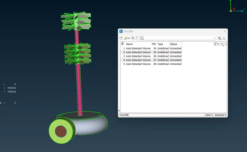
Now I need to find out which volumes are required and which ones are not. I have to mesh volumes which are not occupied by the parent geometry thickness. for the space or voids present indside the component. So only thickness components will be deleted.
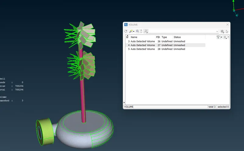
For the remaining volumes, I did volmteric mesh using Remesh option and selecting Tetra CFD (Tetra is element type and CFD is for application). Now the status is meshed.
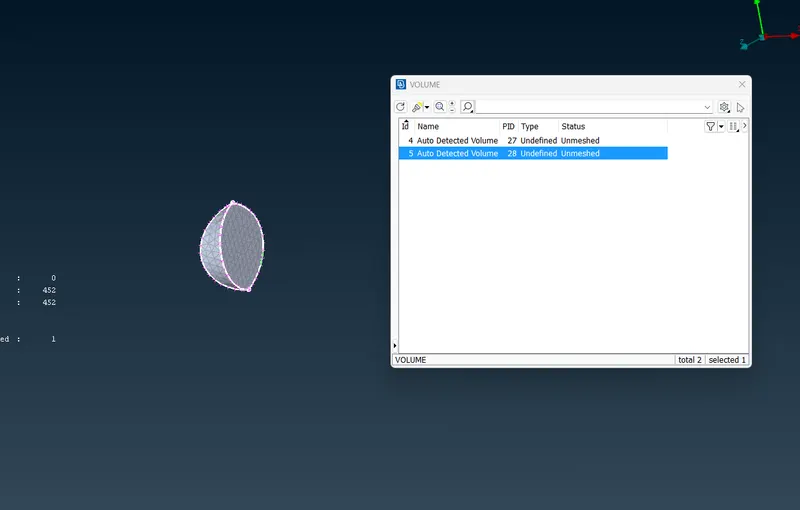
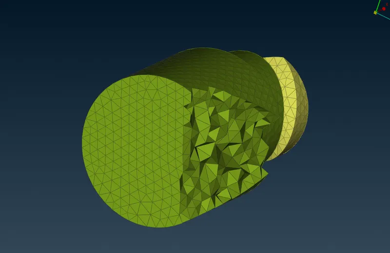
To view the volumtric mesh inside, I used the NOT option with Entity and selected the area to hide.
Now we can see the volumteric mesh formed.