Week 6 - CHT Analysis on a Graphics card
Problem statement:
Perform a steady-state conjugate heat transfer analysis on a model of a graphics card. You can use appropriate materials of your choice for the simulation. Make sure to properly define the correct solid and fluid zones. Refer the video for further clarification and the model is provided below the video.
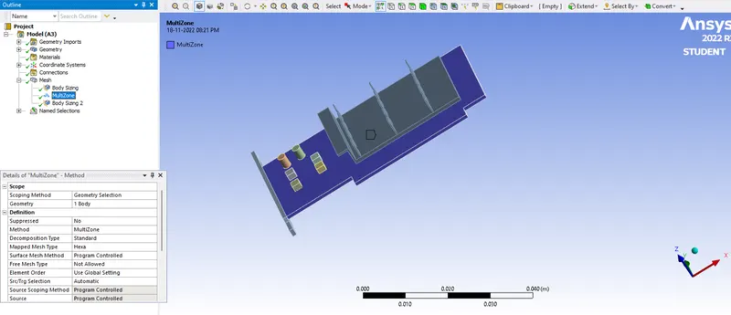
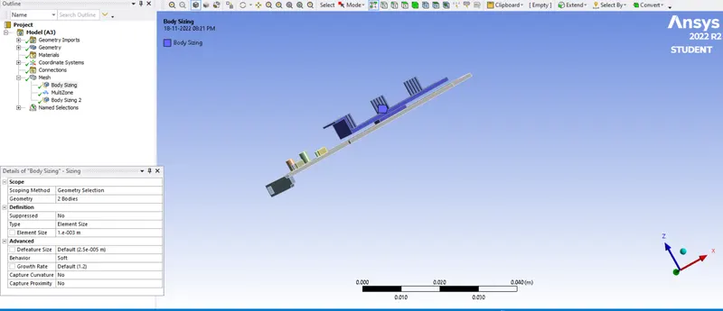
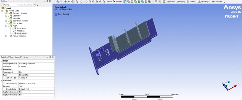
Run the simulation for best possible mesh with combination of coarse and refined mesh in different regions. Explain the reason for choosing the particular mesh settings.
Objective:
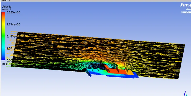
- Run the simulation by varying the velocity from 1m/sec to 5m/sec for at least 3 velocities and discuss the results.
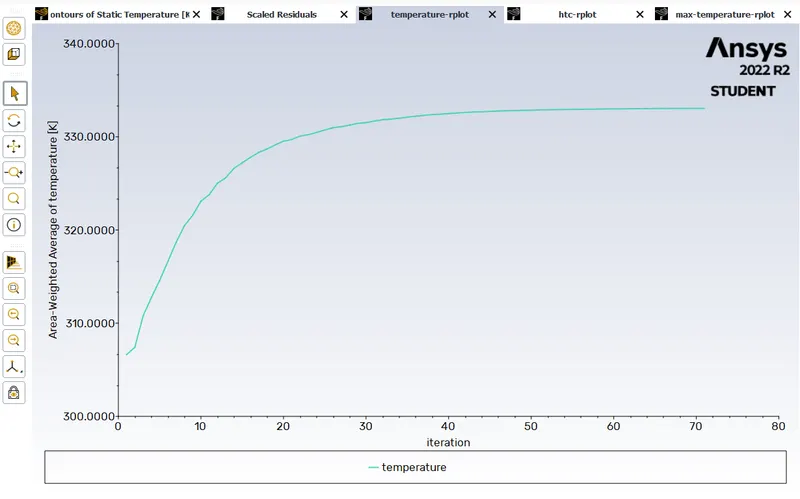
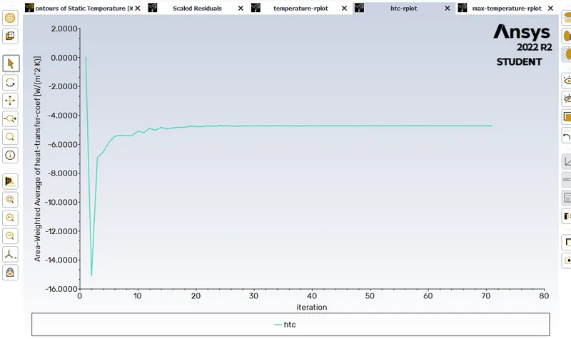
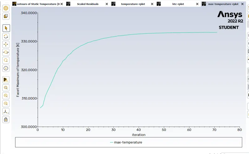
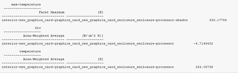
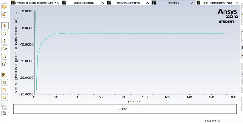
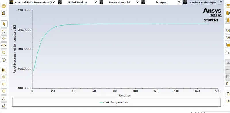
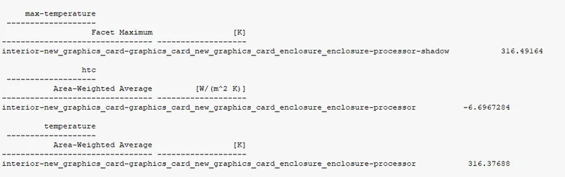
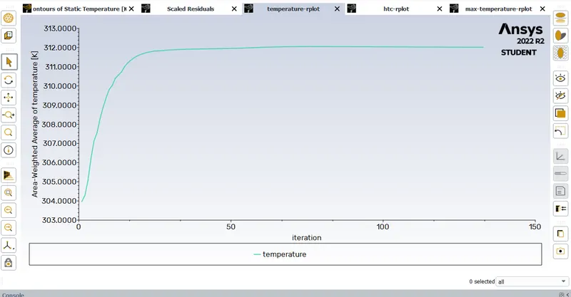
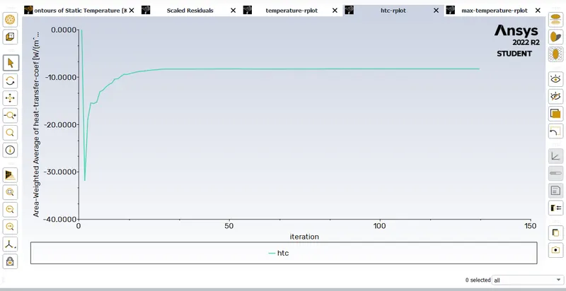
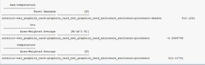
- Find out the maximum temperature and heat transfer coefficient attained by the processor.
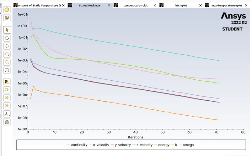
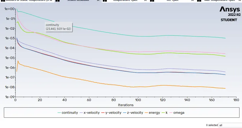
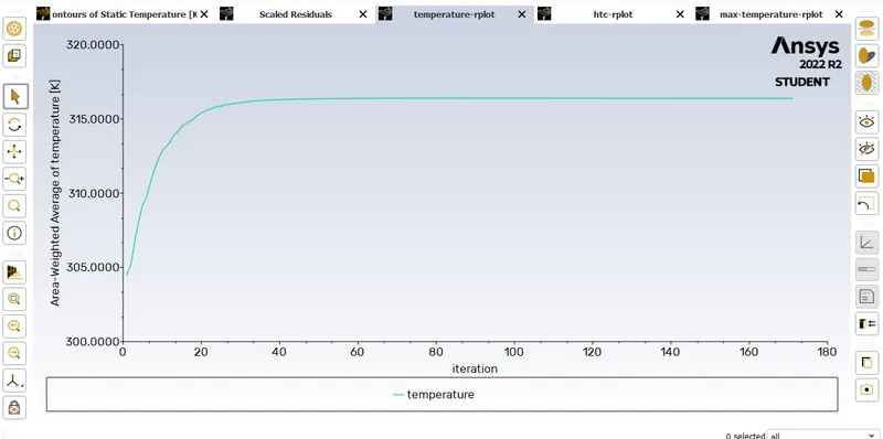
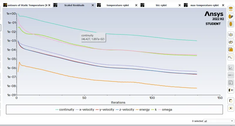
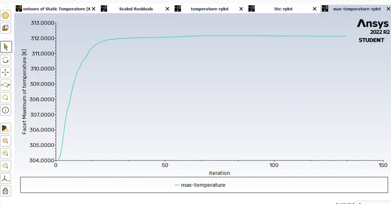
- Prove that the simulation has achieved convergence with appropriate images and plots.
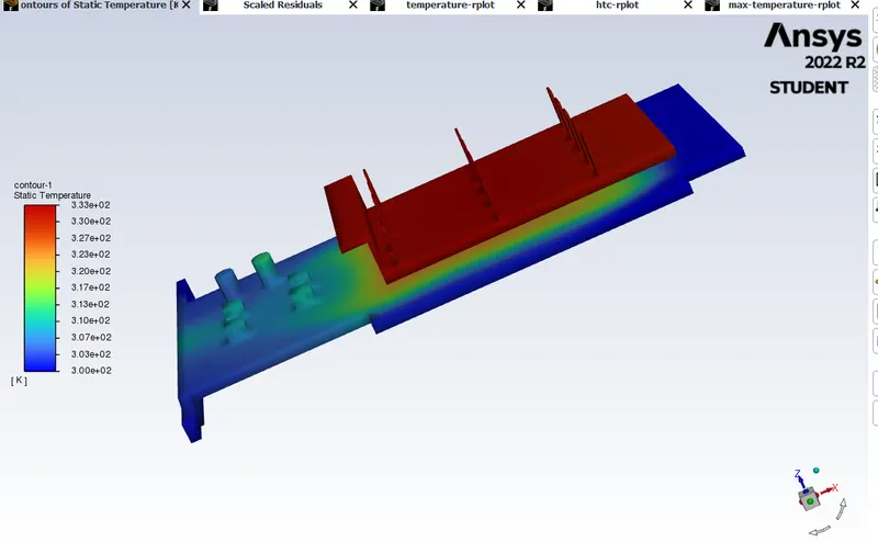
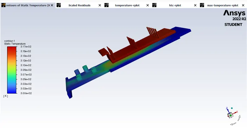
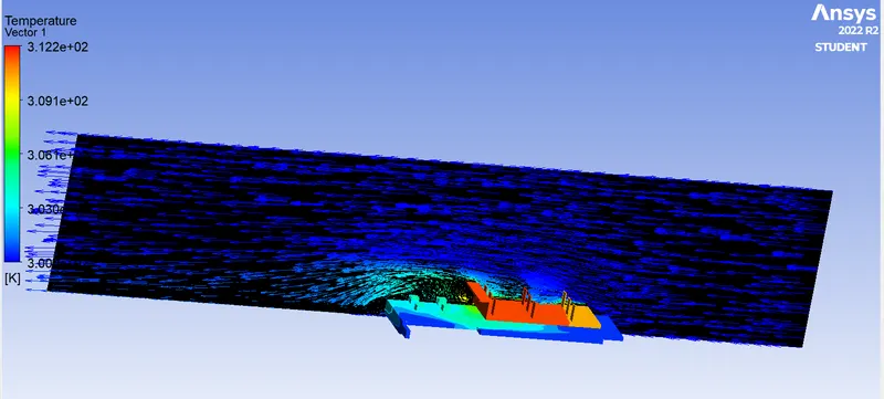
- Identify potential hotspots on the model.
Theory:
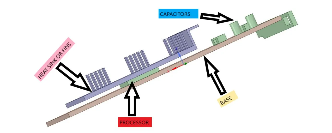
PCB heat sinks are generally used for dissipating heat from the processor. The graphic processor which performs the computational task gets heated up very fast. This can lead to thermal damage to the PCB board and other electronic components. Most modern graphics cards need a proper thermal solution. This can be the liquid solution or heatsinks with an additional connected heat pipe usually made of copper for the best thermal transfer. The correct case; either Mid-tower or Full-tower or some other derivative, has to be properly configured for thermal management. This can be ample space with a proper push-pull or opposite configuration as well as liquid with a radiator either in lieu or with a fan setup.
Graphic Card
Materials:
In this study conjugate heat transfer analysis is performed, so different materials are assigned to solid and fluid domain, which are given below in table.
|
Components |
Materials |
Density |
Specific heat |
Thermal conductivity |
|
Base / PCB |
polystyren |
55 |
1210 |
0.027 |
|
Heat sink/fins |
Aluminum |
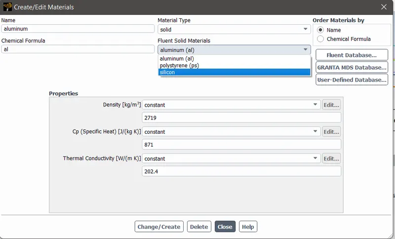
2719 |
871 |
202.4 |
|
Processor |
Silicon |
2330 |
703 |
153 |
|
Enclosure(heat transfer fluid) |
Air |
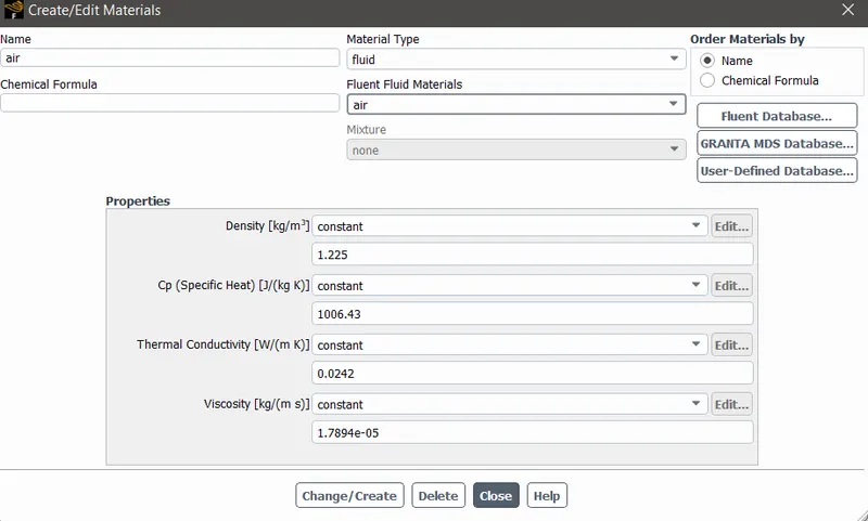
1.225 |
1006.43 |
0.0242 |
Geometery
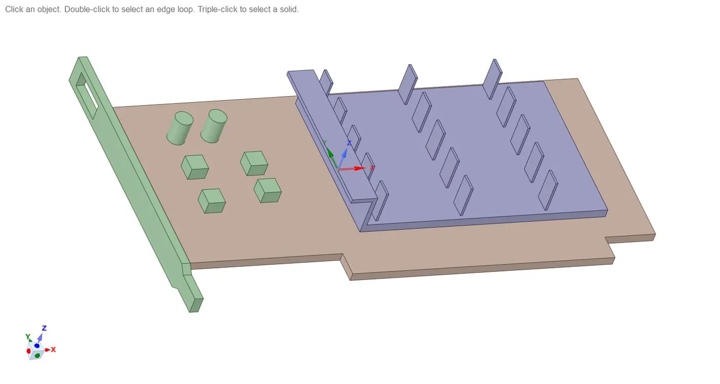
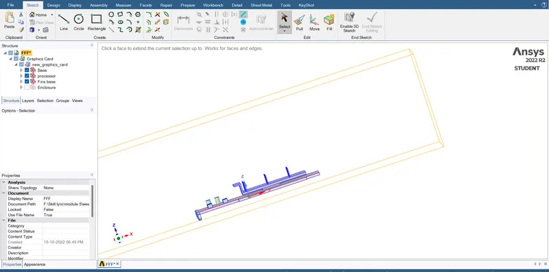
create shared topology, to avoid overlapping of mesh pattern at different regions of domain.
Mesh
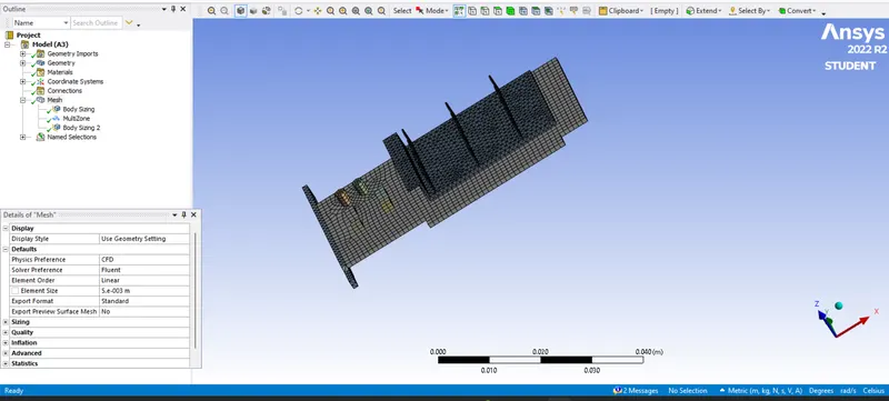
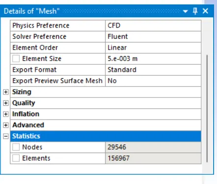
Base mesh =5 mm
mesh size for fins processor and base =1 mm
number of elements
Setup
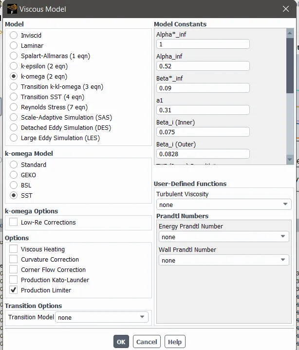
Steady state analysis is performed .
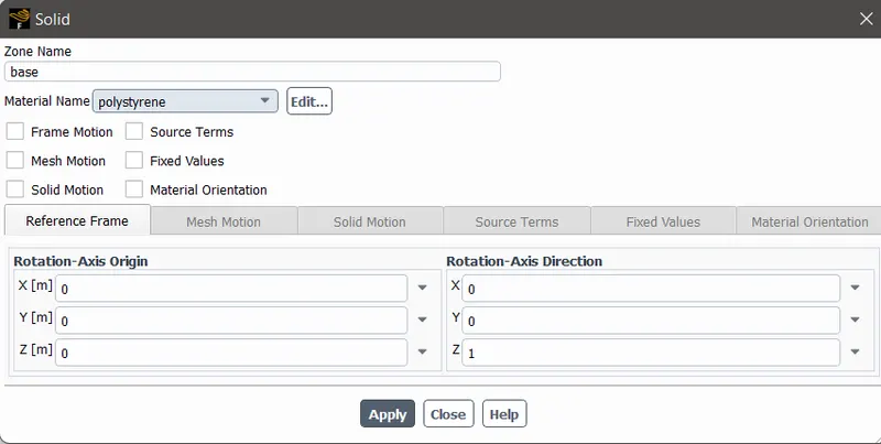
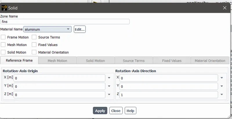
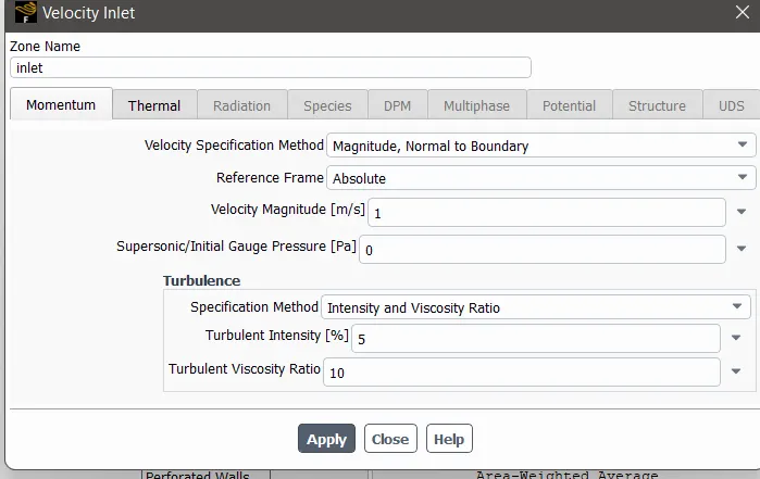
according to the given data material is created
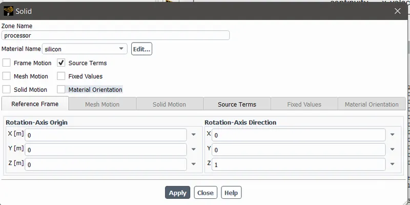
Heat generated rate =Q/Volume
Let us assume Q=1 watt
Volume of the processor = 64mm^3
Heat Generated rate = 15625000 W/m^3
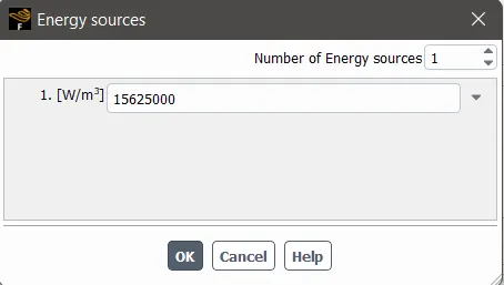
similarly all the materials are assigned to their respective zones
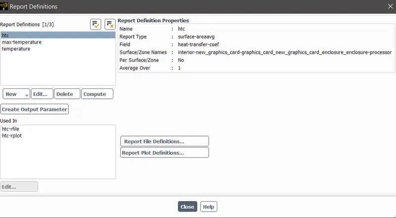
Create definations for heat transfer cofficient , Temerature and Maximum temperature.
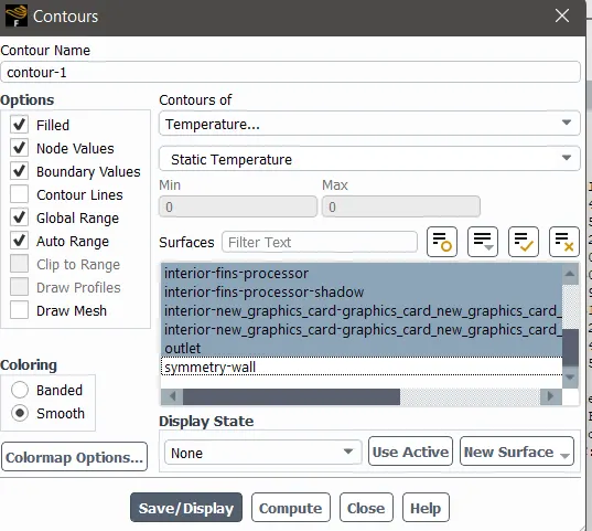
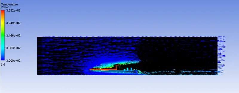
Create contour for temperature
Case-1
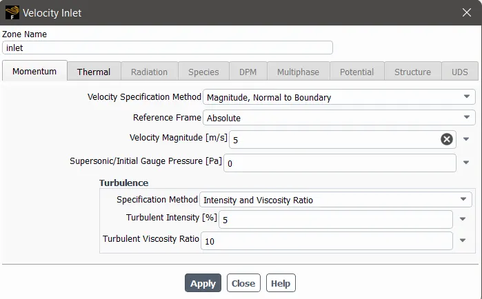
Velocity=1 m/sec
Output
Case -2
Velocity=3m/sec
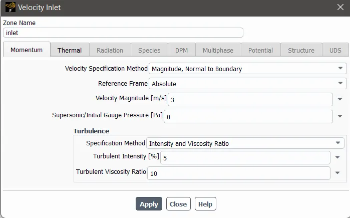
Output
Scaled Residuals
Case -3
Velocity=5 m/sec
output
Scaled Residuals
Conclusion -
|
Inlet velocity (m/s) |
Temperature of processor(k) |
Heat transfer coefficient |
Maximum Temperature |
|
1 |
333.057 |
4.7149 |
333.177 |
|
3 |
316.37 |
6.6967 |
316.49 |
|
5 |
312.017 |
8.2566 |
312.1261 |
- The thermal performance is seen to get improved increasing velocity of air and refining the mesh more.
- The maximum temperature of the processor is seen to decrease with the increase in velocity of air.
- The convergence criteria are satisfactorily achieved for baseline and refined mesh setup.
- The hot spot zones are clearly mentioned, which shows the area prone to thermal damage.