Week 6 - CHT Analysis on a Graphics card
CHT Analysis on a Graphics card
OBJECTIVE
- To perform steady-state conjugate heat transfer analysis on Graphics Card
- To find the effect of different velocities on the temperature
Discription:
CHT provides the temperature prediction and the hotspot regions at the solid-fluid interface and we can also predict the heat transfer accurately for example- Conduction through solids, convection through fluid, and thermal radiation. It also provides the velocity and pressure distribution of fluid moving inside the solid. We can also use CHT in design optimization for improvement for heat transfer and cooling capacity.
Ansys Setup:
Geometry:
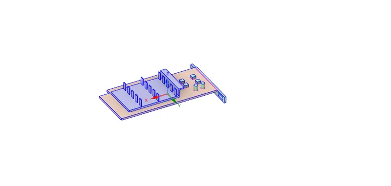
There are three parts in the graphics
1.Base
2.Fins
3.Processor
create the enclosure for setting up fluid domain
Meshing
Mesh the geomerty with required element size.
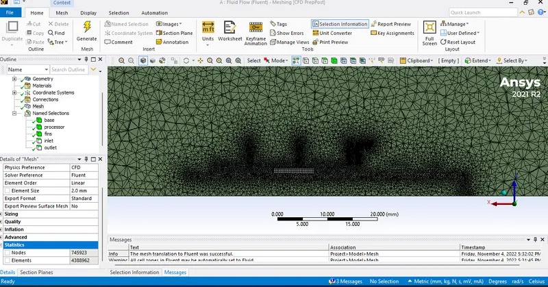
Fluent set up:
complete the all reqisite all attributes like
solution type: pressure based;
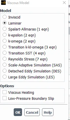
physical Model : Laminar
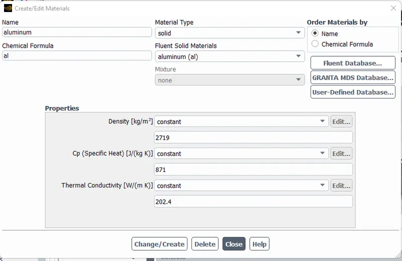
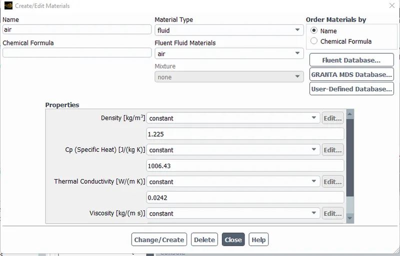
Material : base- wood;
: Fins - Alluminium
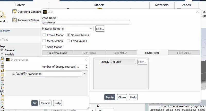
: Processor - Silicon;
: Air
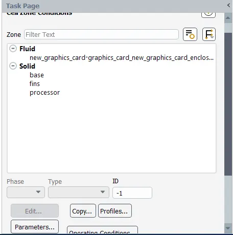
Cell zones - Air-fluid zone
Base, Alluminium,Silcon-solid zones
Sourse - Heat sourse as Processor
Boundary conditions : input - velocity input as 1 m/s
: out put - pressure output
solution Method : Simple ,
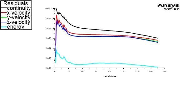
Run the siulations
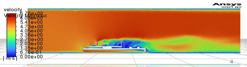
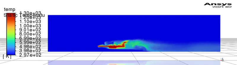
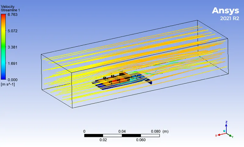
Results
| vel(m/s) | processor(w/m^2K) |
| 5 | 626.19599 |
| 3 | 443.70367 |
| 1 | 287.89605 |
Disccusions :
1.As the number of elements increases the accurate results of temperature distribution is obtained
2.As velocity is increased heat transfer coefficient is increased
3. From the above table, it is fairly notable that, the net temperature of components of graphics cards decreases with an increase in inlet velocity.