Week 6 - CHT Analysis on a Graphics card
AIM:
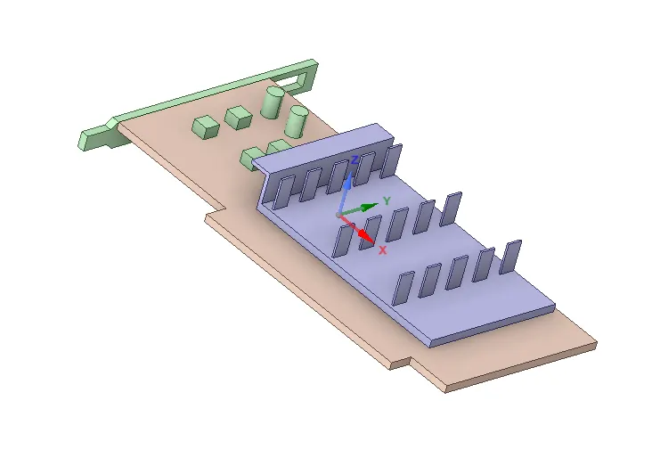
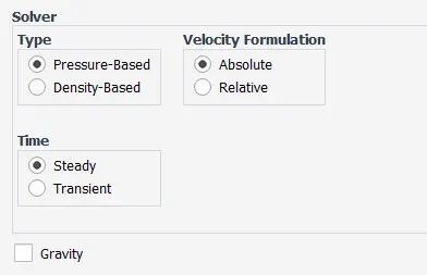
To perform a steady-state conjugate heat transfer analysis on a model of a graphics card.
PROJECT OBJECTIVE:
- Run the simulation by varying the velocity from 1m/sec to 5m/sec for at least 3 velocities and discuss the results.
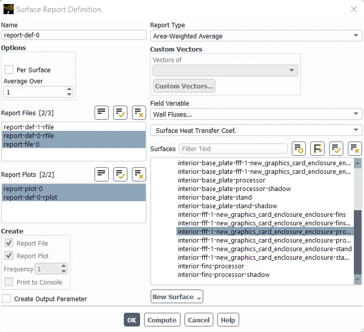
- Find out the maximum temperature and heat transfer coefficient attained by the processor.
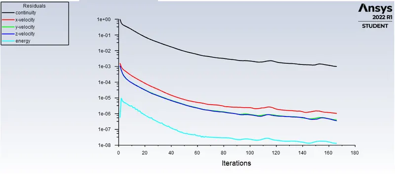
- Prove that the simulation has achieved convergence with appropriate images and plots.
- Identify potential hotspots on the model.
SOLUTION:
CHT analysis:
The Conjugate Heat Transfer (CHT) analysis type allows for the simulation of heat transfer between solid and fluid domains by exchanging thermal energy at the interfaces between them. This type of heat transfer includes both convection (between fluids) and conductive (between solids) heat transfer, as well as both forced and natural convection.
Common applications and use cases of this thermal simulation type include electronics cooling, heat exchangers, industrial machinery, some AEC cases, and more.
The CHT approach has an advantage over FE thermal analyses in that wall heat transfer coefficients and their local variations on surfaces are directly calculated within the model rather than based on simplified empirical calculations. The CHT approach therefore has benefits for those applications where heat transfer is either non-uniform or difficult to calculate empirically. Heat sinks are optimized to combine heat transfer by conduction in the heat sink with the convection in the surrounding fluid.
Heat Transfer in a Solid
In most cases, heat transfer in solids, if only due to conduction, is described by Fourier’s law defining the conductive heat flux, q, proportional to the temperature gradient:  .
.
For a time-dependent problem, the temperature field in an immobile solid verifies the following form of the heat equation:

Heat Transfer in a Fluid
Due to the fluid motion, three contributions to the heat equation are included:
- The transport of fluid implies energy transport too, which appears in the heat equation as the convective contribution. Depending on the thermal properties on the fluid and on the flow regime, either the convective or the conductive heat transfer can dominate.
- The viscous effects of the fluid flow produce fluid heating. This term is often neglected, nevertheless, its contribution is noticeable for fast flow in viscous fluids.
- As soon as a fluid density is temperature-dependent, a pressure work term contributes to the heat equation. This accounts for the well-known effect that, for example, compressing air produces heat.
Accounting for these contributions, in addition to conduction, results in the following transient heat equation for the temperature field in a fluid:

Efficiently combining heat transfer in fluids and solids is the key to designing effective coolers, heaters, or heat exchangers.
The fluid usually plays the role of energy carrier on large distances. Forced convection is the most common way to achieve high heat transfer rate. In some applications, the performances are further improved by combining convection with phase change (for example liquid water to vapor phase change).
Even so, solids are also needed, in particular to separate fluids in a heat exchanger so that fluids exchange energy without being mixed.
Heat sinks are usually made of metal with high thermal conductivity (e.g. copper or aluminum). They dissipate heat by increasing the exchange area between the solid part and the surrounding fluid.
Energy Savings
Heat transfer in fluids and solids can also be combined to minimize heat losses in various devices. Because most gases (especially at low pressure) have small thermal conductivities, they can be used as thermal insulators… provided they are not in motion. In many situations, gas is preferred to other material due to its low weight. In any case, it is important to limit the heat transfer by convection, in particular by reducing the natural convection effects. Judicious positioning of walls and use of small cavities helps to control the natural convection. Applied at the micro scale, the principle leads to the insulation foam concept where tiny cavities of air (bubbles) are trapped in the foam material (e.g. polyurethane), which combines high insulation performances with light weight.
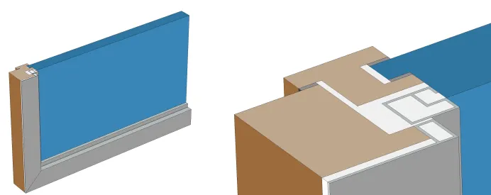
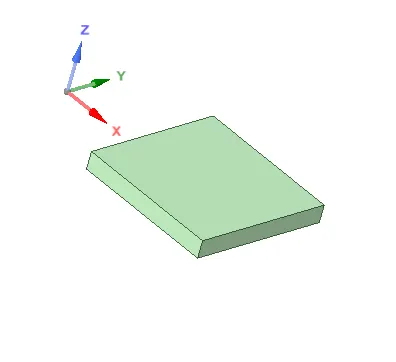
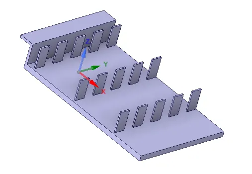
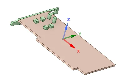

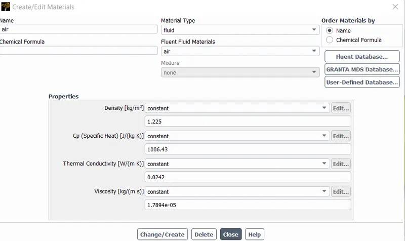
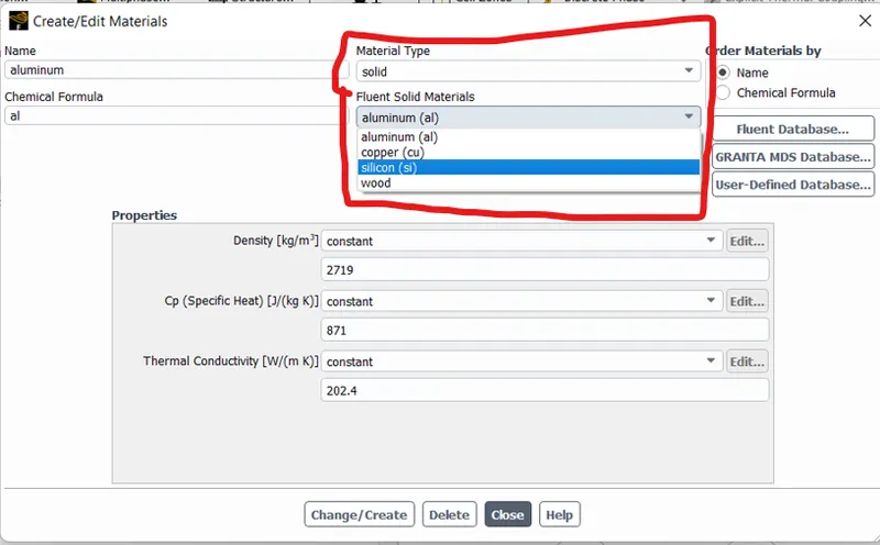
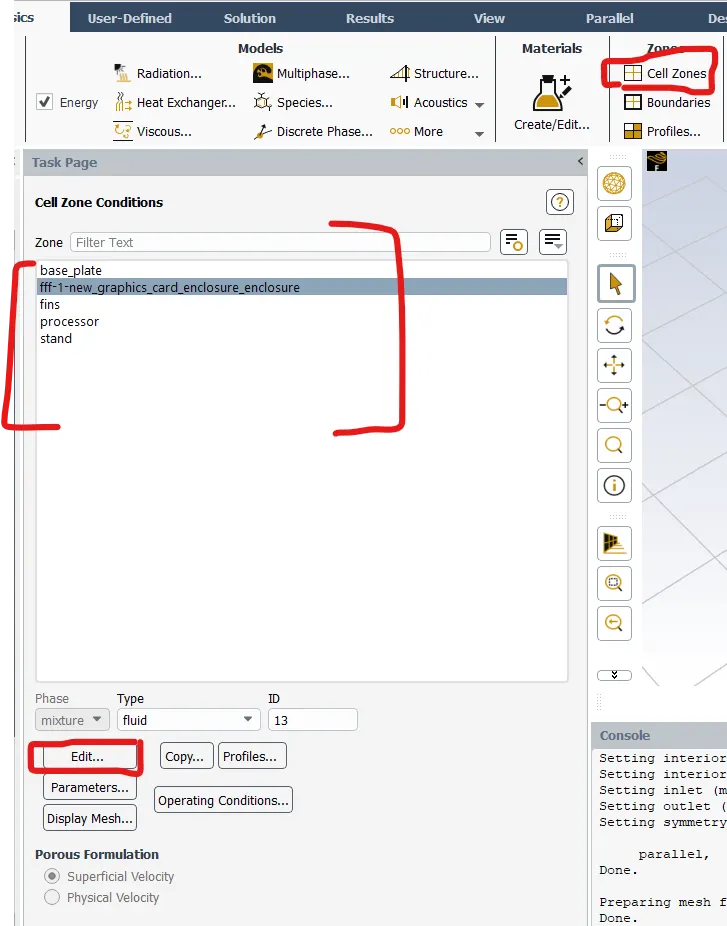
- The above solid materials can be assigned to the components in the cell zones. Click cell zones in zones ribbon tab.
- Then select the required component and click edit.
- Then change the required materials as required which is entered in the materials section that has been taken from the fluent database or the properties of the materials has been entered manually.
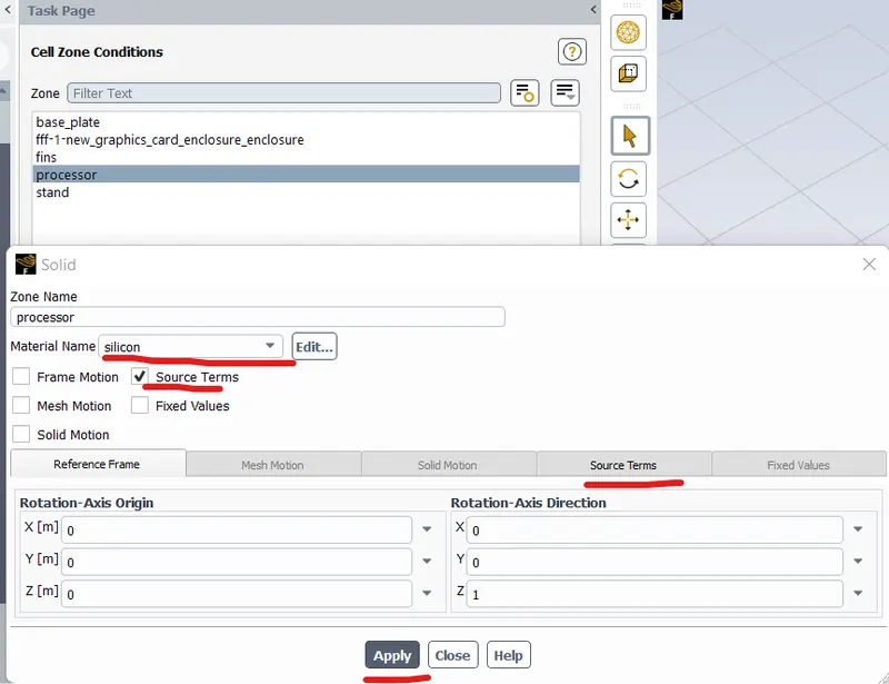
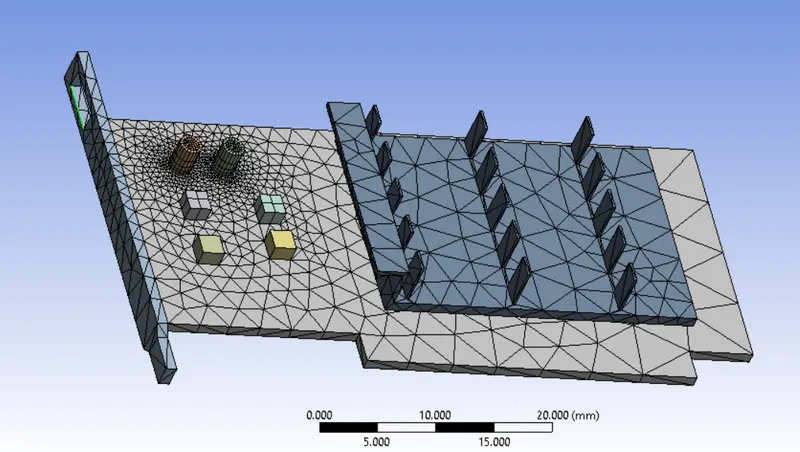
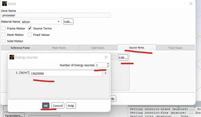
- Since the processor is generating heat, we need to provide the heat generation in W/m^3 in source terms.
- Assuming the processor is generating 1 Watt of heat and the heat generation will be in W/m^3. So Heat generated divided by volume of the processor gives the heat generation rate.
- Volume of the processor= 8x8x1 mm^3 = 64 mm^3
Therefore, Heat generation per unit volume is (1 W)/(64 * e-9 m^3 ) = 15625000 W/m^3.
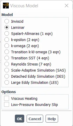
Viscous model:
The flow is taken as laminar.
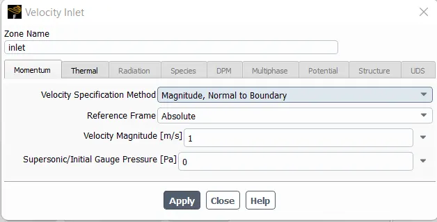
Boundary conditions:
The inlet velocity is taken as 1 m/s, 3 m/s and 5 m/s and the ambient temperature condition is taken as 300 K and simulation is performed.
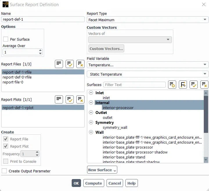
- To find the maximum temperature in the processor where the heat is generated, we have to create the Facet maximum in the surface report.
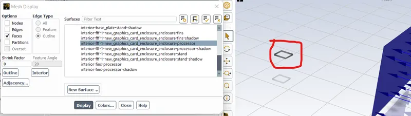
- Then select field variable as Temperature and Static temperature and select the processor in the named selection list to find the maximum temperature in that component.
Time scale factor: 1
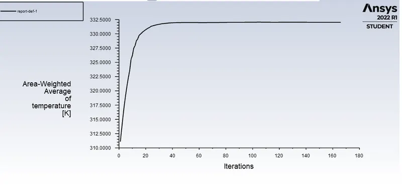
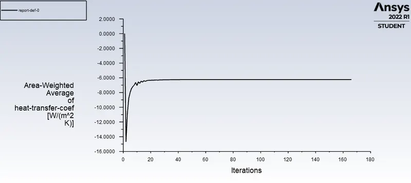
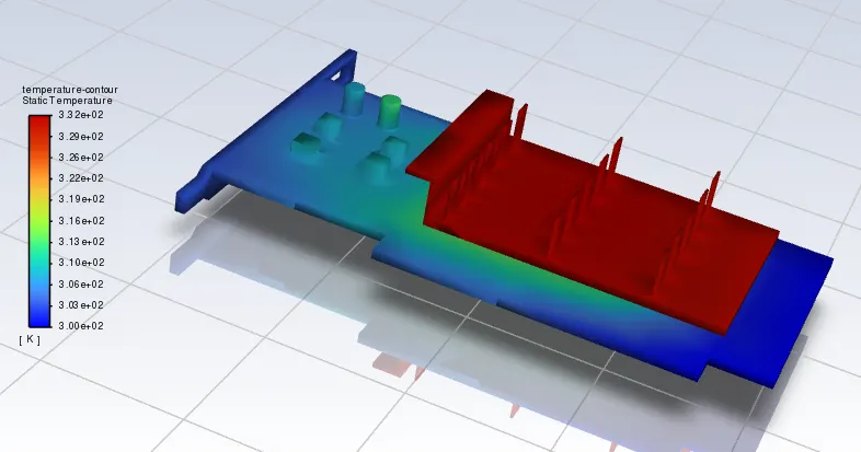
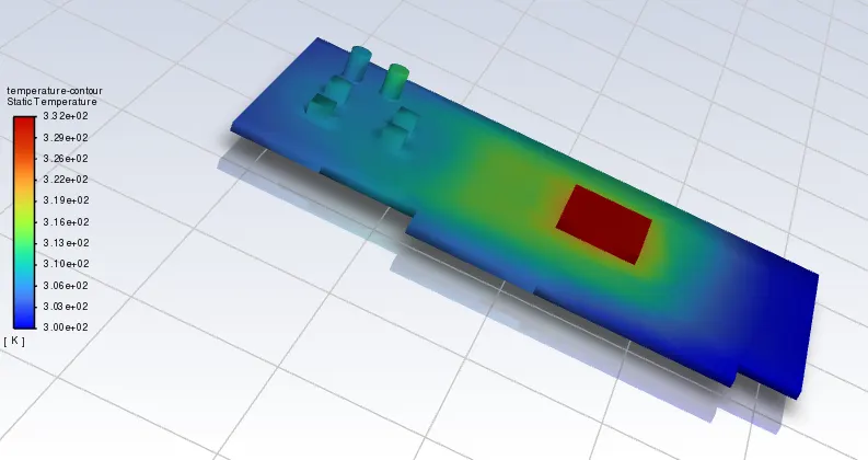
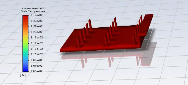
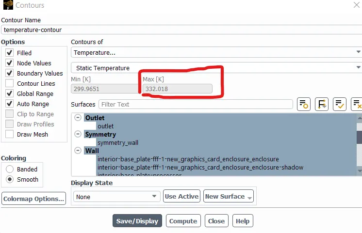
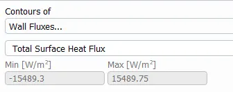
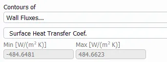

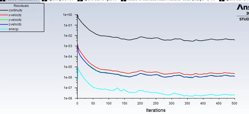
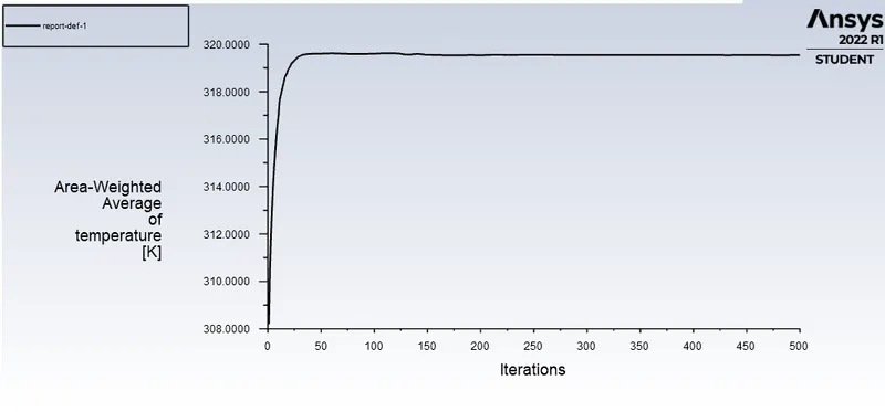
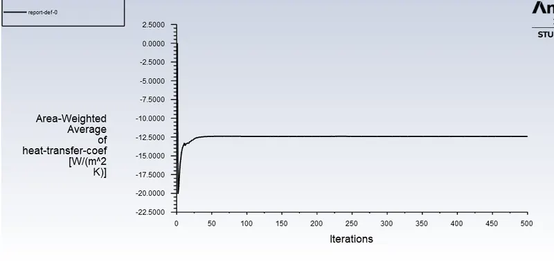
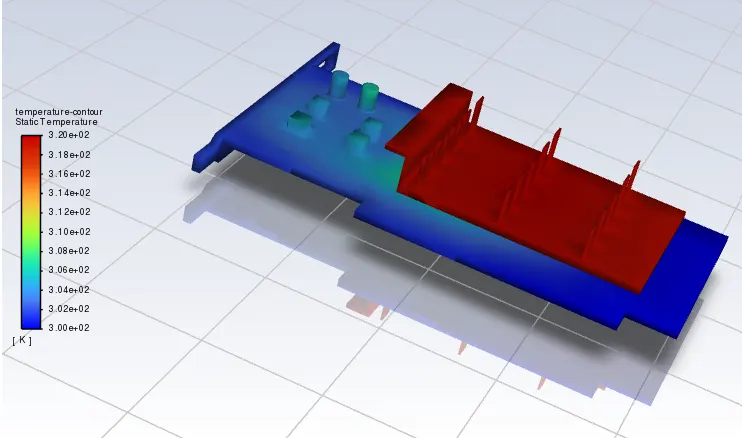
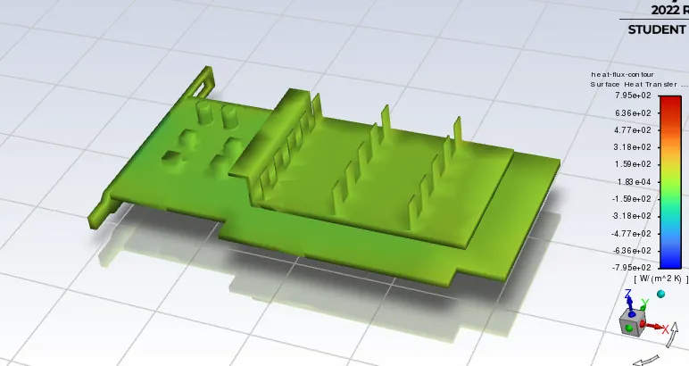
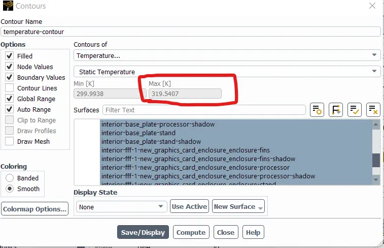
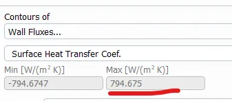
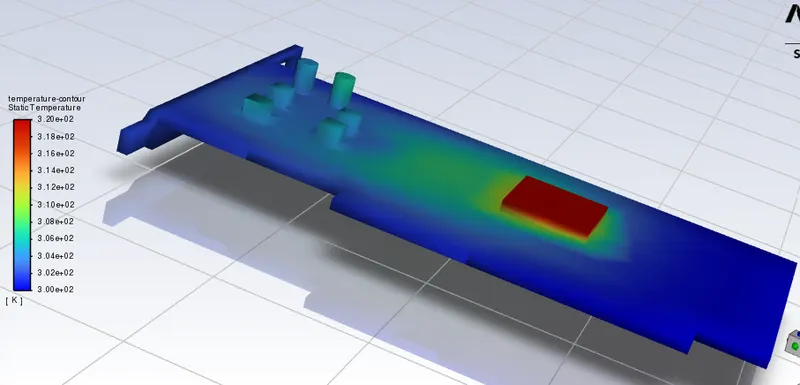
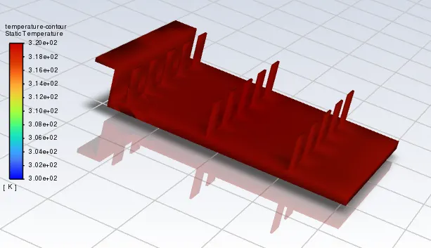
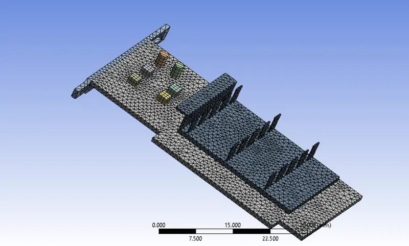

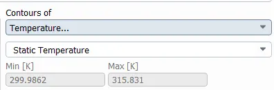
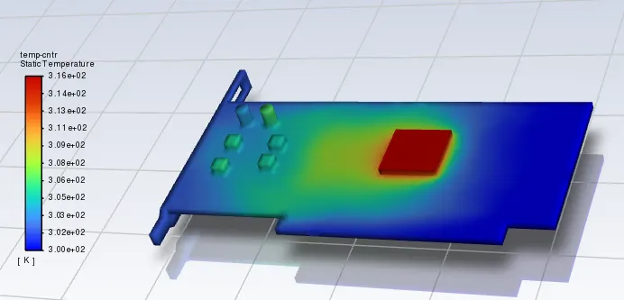
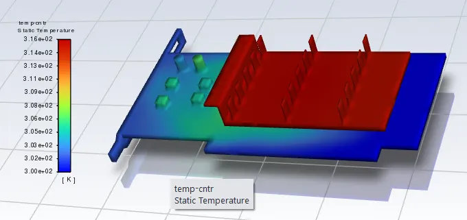
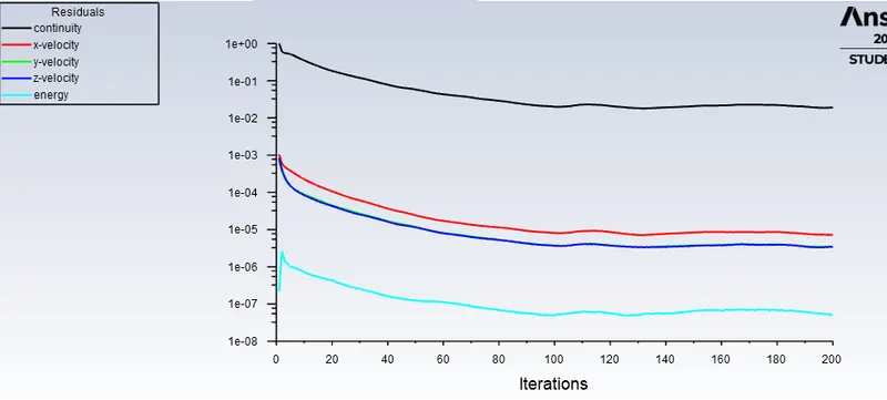
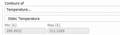
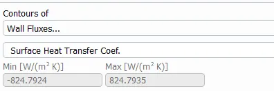
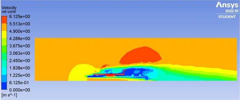
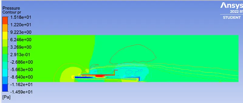
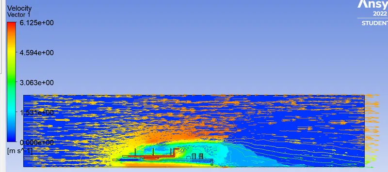
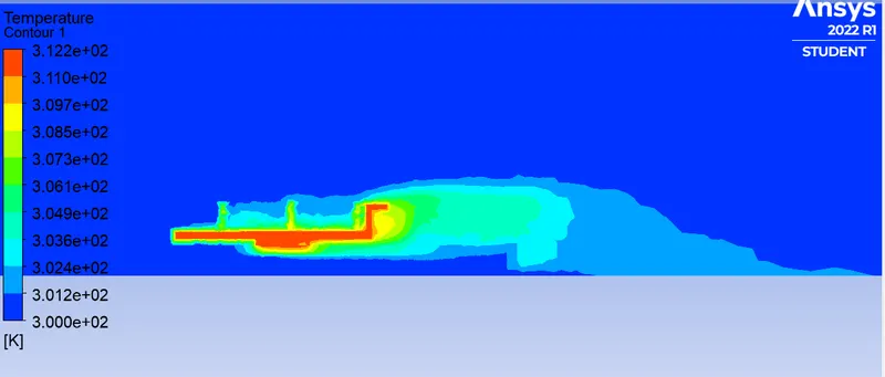
- It is observed that as the velocity of the air increases, the maximum temperature at the processor decreases.
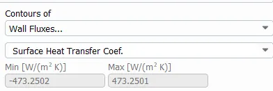
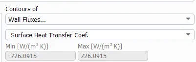
- As the velocity of the air increases, the surface heat transfer co-efficient also increases.
- The temperature at the processor and the fins are at maximum compared to the other surfaces of the graphic card.
- There is some vortex formations at the end of the fins at the graphics card.
- The velocity is maximum before coming in contact with the graphic card and decreases at the surfaces surrounding to the card and the peak values are observed in the region above the card.
- The pressure is maximum at the entry of the graphic card board where the air rushes the card at entry.
- As the velocity of air increases, the heat carried by the air from the surface increases, thus decreasing the peak temperature and increasing the surface heat transfer co-efficient. The heat transfer co-efficient is nothing but the heat observed per unit surface area per unit temperature.
- From the results, it is observed that the values of the processor and fins are almost equal which we can conclude that fin efficiency is satisfied.
- In my opinion, the flow of the air can be taken in 'Y' direction instead of choosing 'X' direction since in 'Y' direction it covers maximum surface area in coming contact with the air flow thus increasing heat transfer which the fin effectiveness can be increased further.