Week 6 - CHT Analysis on a Graphics card
The aim of this exercise is to simulate steady state conjugate heat transfer analysis on a model of a graphic card by assigning appropriate materials and varying velocity of air flow.
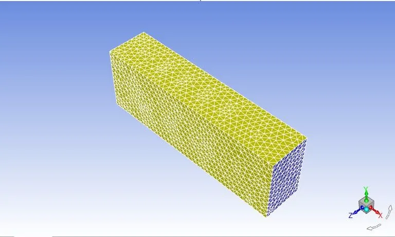
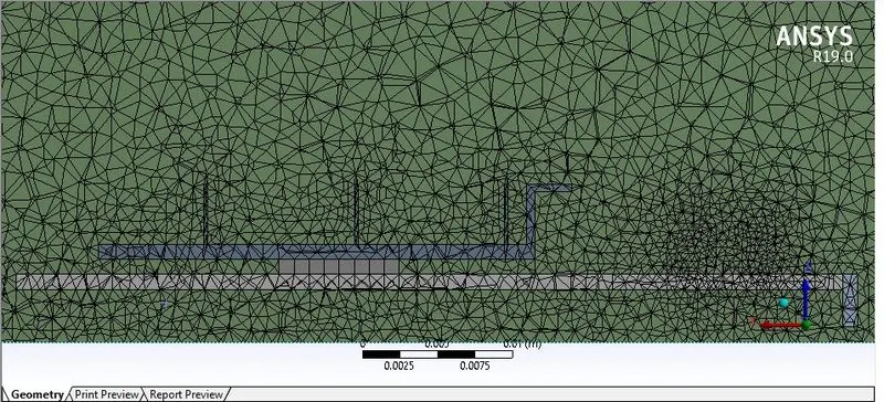
For this, we import the model of the graphics card into spaceclaim, we enable share topology for the components and the load into meshing. In meshing, we name the components individually as walls, processor, pcb and fins and then specify the sizing according to the mesh type required (coarse or fine). Then after generating the mesh, we enter fluent where we specify double precision and then in setting up domain, we use the check option to check the mesh quality. After checking the mesh for any deficiencies, we proceed to setting up physics where we choose steady state pressure based, absolute solver with energy equation turned on. Now, we choose k-epsilon viscous model for the problem and move on to material specification.
In material, we first have air as fluid in the enclosure, user defined material for the pcb, and processor and finally, aluminium for fins. Then in zones, we specify each of the materials to the components and set the processor as the source with heat flux. Then in boundaries, we specify the boundary conditions with velocity at the inlet ranging from 1 to 3 and the pressure at outlet set to 0. Now, we initialize the process and then add the necessary contours required and then run the simulation.
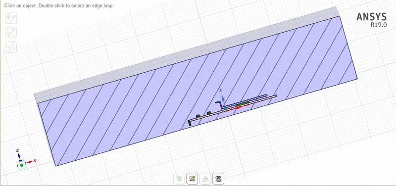
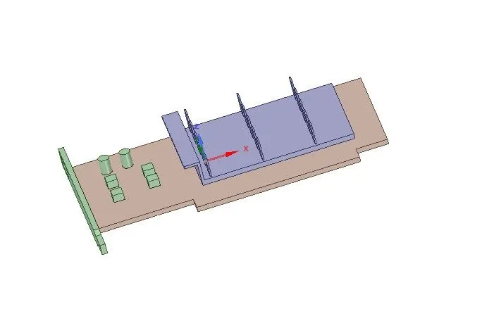
For coarse mesh with size of 0.5mm:
Velocity = 1m/s:
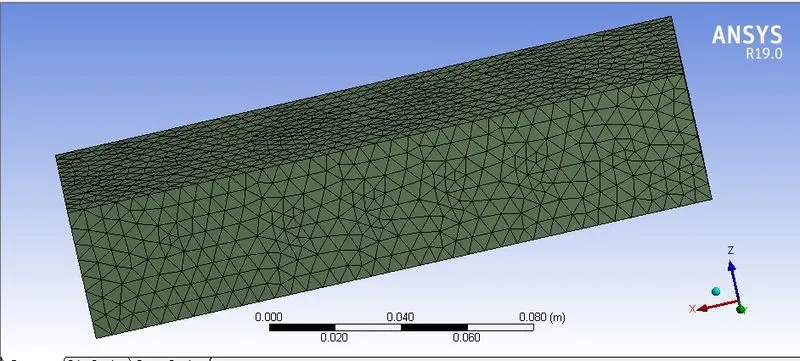
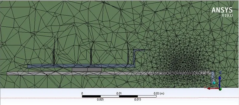

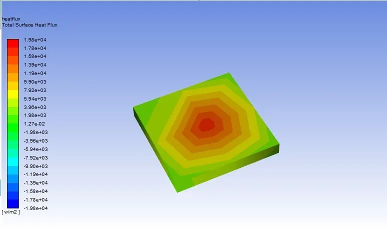
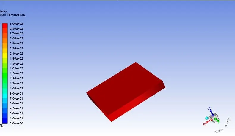
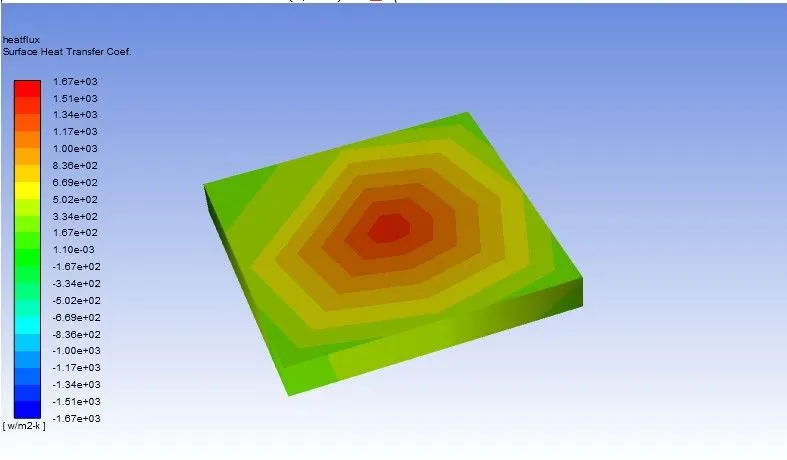
For velocity = 3m/s:
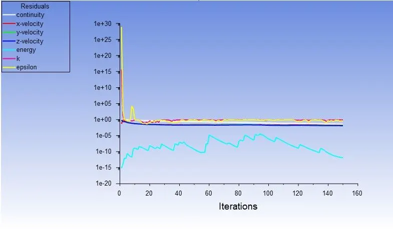
For velocity = 5m/s:
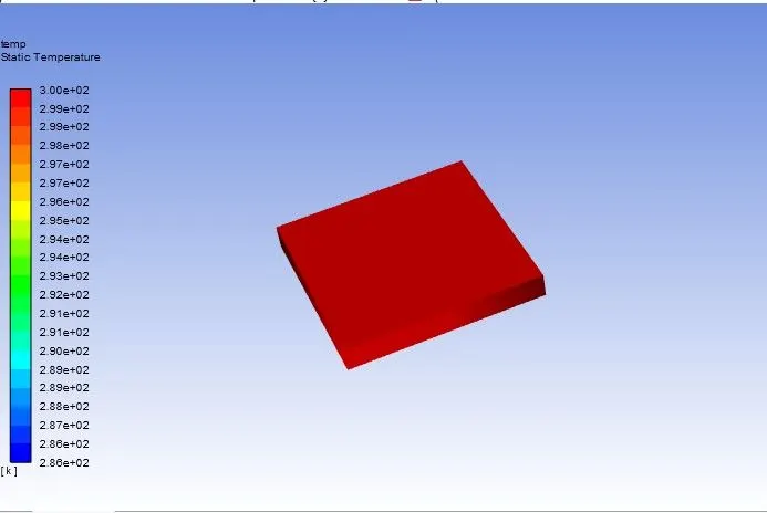
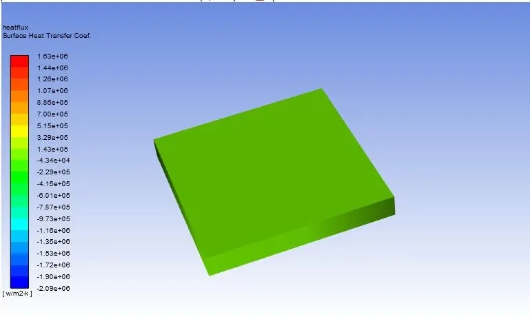
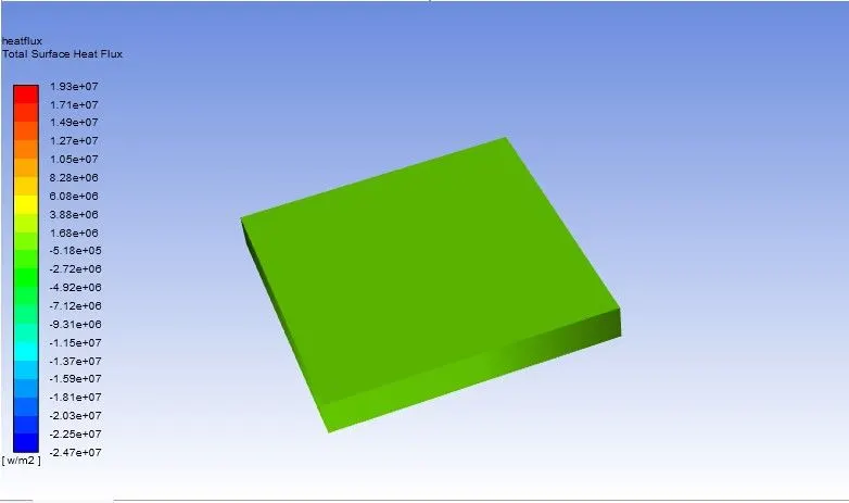
For fine mesh with mesh size of 1mm:
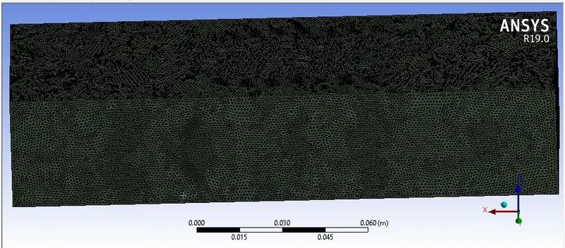
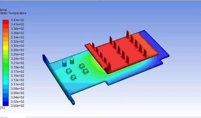
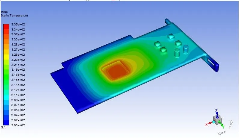
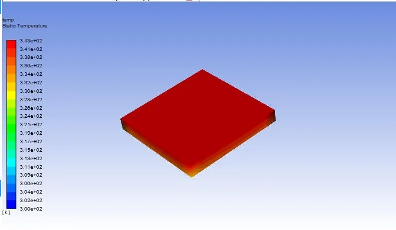
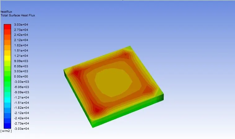
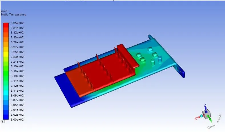
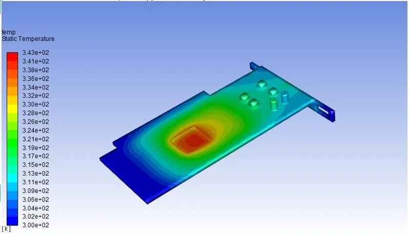
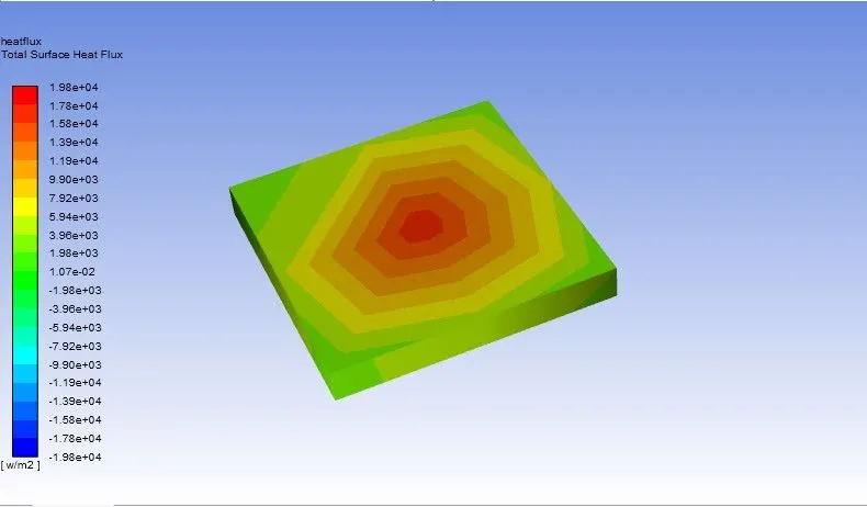
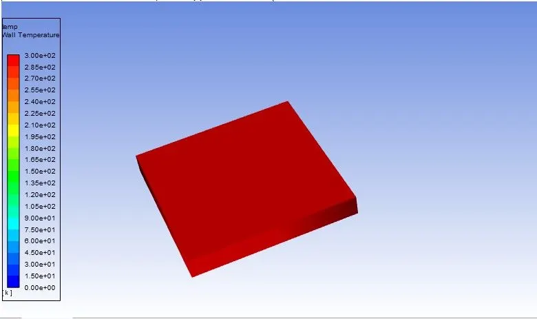
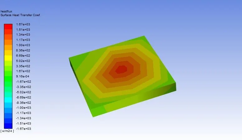
From the above plots, it is evident that with refined mesh size, we can accurately find the locations of hotspots due to the source of heat flux generated. Also, as mesh size is increased, the simulation time increases and the heat transfer is clearly evident in the regions where the walls are adjascent to each other. Also, when the inlet air velocity is increased, there is less heat transfer between the components as the fins are efficiently cooled which helps to regulate the processor temperature at optimum levels.
In the case of higher inlet velocities, the maximum temperature decreases and the heat transfer coefficient increases and this helps us to monitor the region where the hotspots are present.
Some of the hotspot regions are the adjacent surfaces to the processor, which is the source like the fins and the pcb. Apart from the fins, the heat transfer takes place from the fins to the components in the pcb and this can be seen in the plots.