Week 6 - CHT Analysis on a Graphics card
Aim
To perform a steady-state conjugate heat transfer analysis on a model of a graphics card.
Introduction
The contemporary conjugate convective heat transfer model was developed after computers came into wide use in order to substitute the empirical relation of proportionality of heat flux to temperature difference with heat transfer coefficient which was the only tool in theoretical heat convection since the times of Newton. This model, based on a strictly mathematically stated problem, describes the heat transfer between a body and a fluid flowing over or inside it as a result of the interaction of two objects. The physical processes and solutions of the governing equations are considered separately for each object in two subdomains. Matching conditions for these solutions at the interface provide the distributions of temperature and heat flux along the body–flow interface, eliminating the need for a heat transfer coefficient.
Theory
The Conjugate Heat Transfer (CHT) analysis type allows for the simulation of heat transfer between solid and fluid domains by exchanging thermal energy at the interfaces between them. Typical applications of this analysis type exist as, but are not limited to, the simulation of heat exchangers, cooling of electronic equipment, and general-purpose cooling and heating systems.
Objectives
- Run the simulation by varying the velocity from 1m/sec to 5m/sec for at least 3 velocities and discuss the results.
- Find out the maximum temperature and heat transfer coefficient attained by the processor.
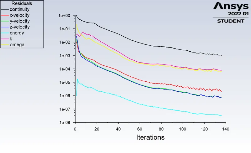
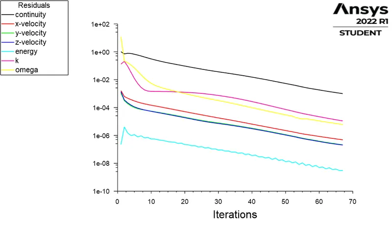
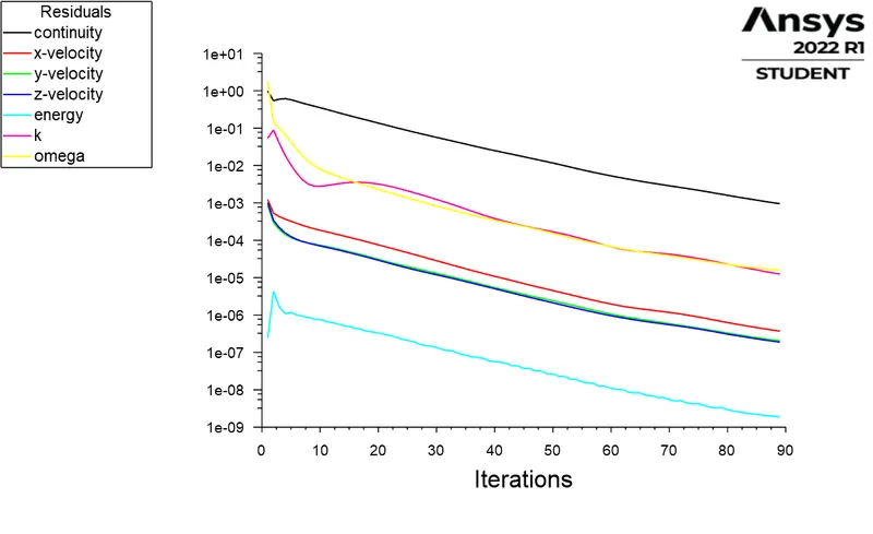
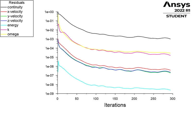
- Prove that the simulation has achieved convergence with appropriate images and plots.
- Identify potential hotspots on the model.
Procedure
Pre-processing
Spaceclaim
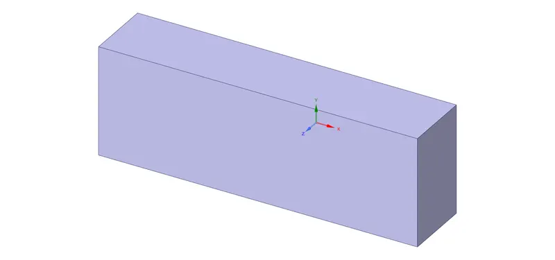
The geometry is imported into spaceclaim and using the options structure`rarr`Analysis`rarr`topology to share and the using the Share option in workbench the edges and the surfaces are shared between the solid bodies and the enclosure
Processor
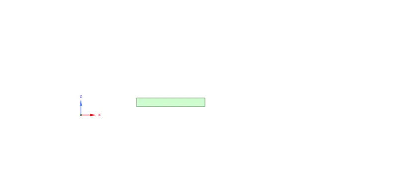
Fins
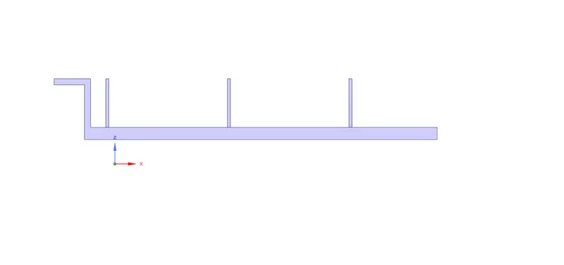
Base
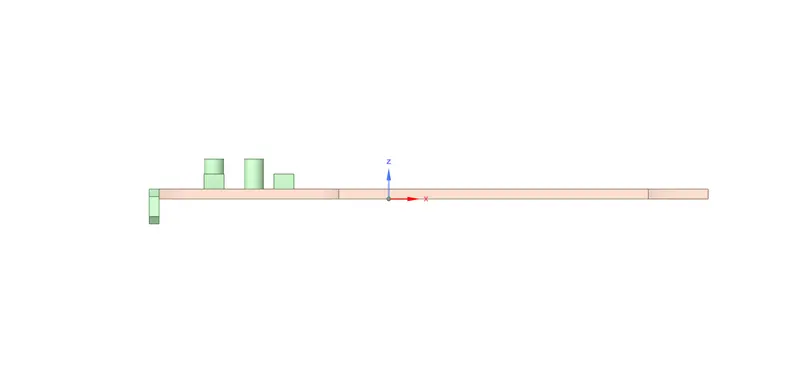
Graphic card
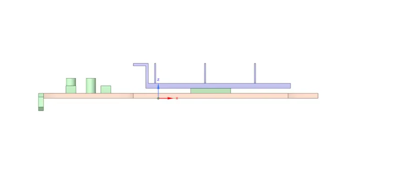
Enclosure
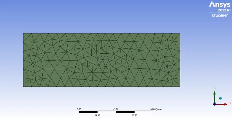
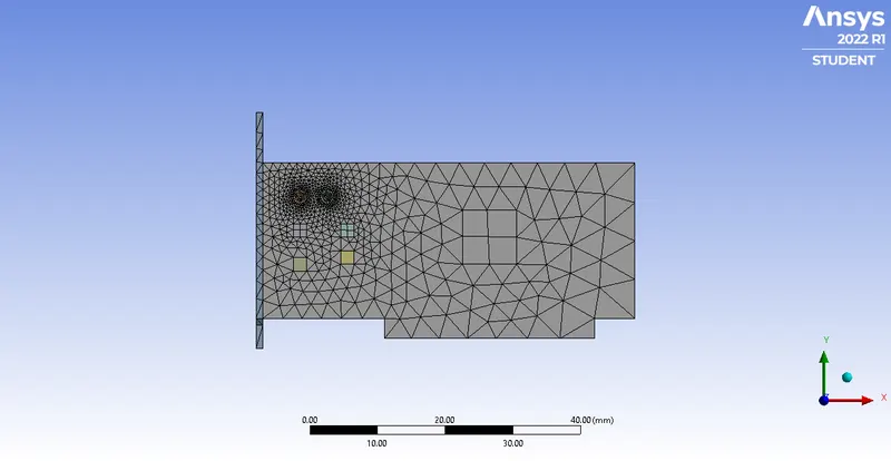
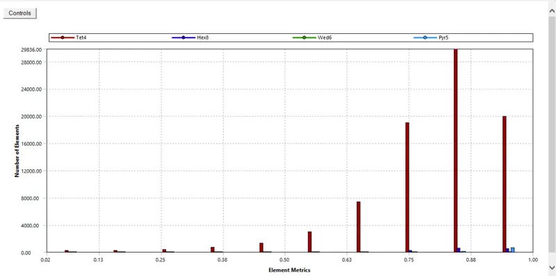
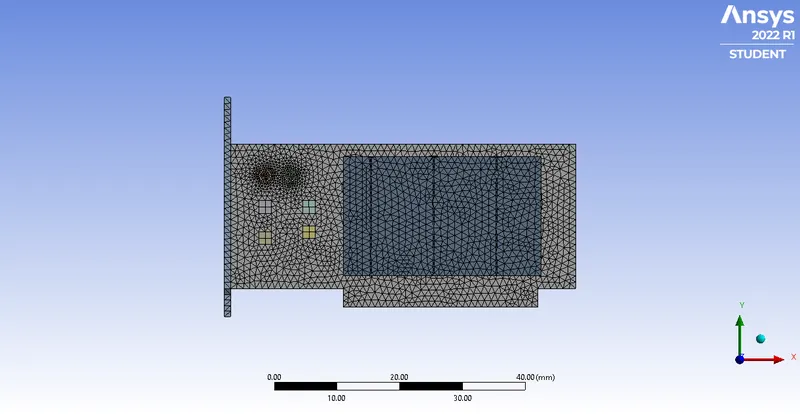
Base mesh
The default mesh is used here
No of elements:83706
Setup
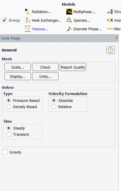
The setup begins with setting up the physics, beginning with energy and selecting k-`omega`model flow
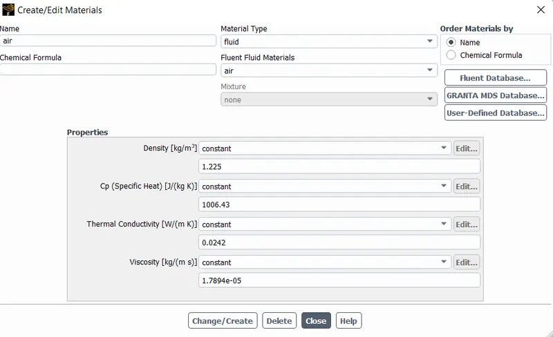
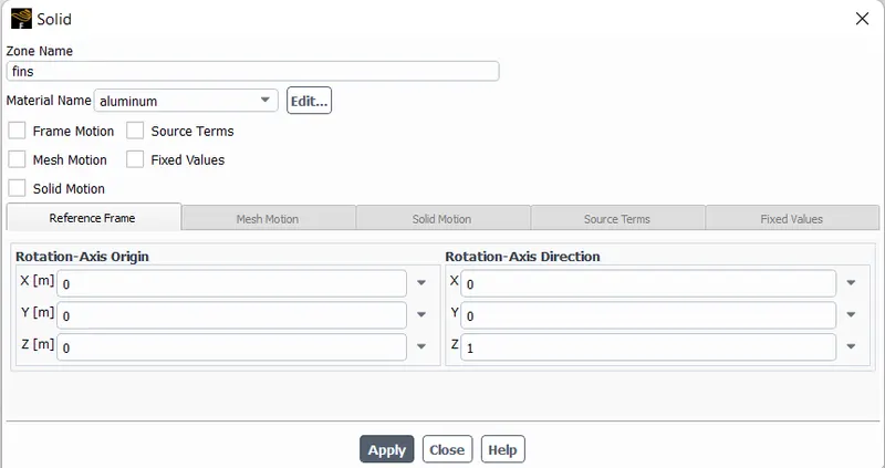
Diiferent parts of the graphic card are assigned with different solids
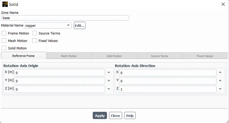
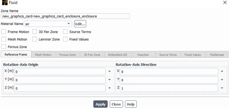
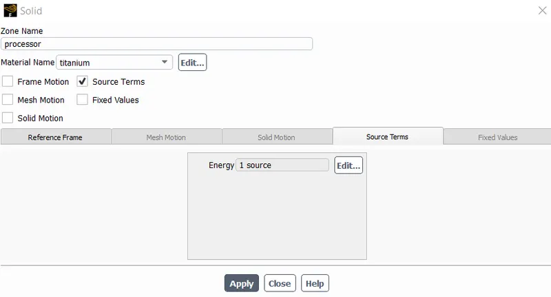
The processor is where the heat gets generated so the source term is added
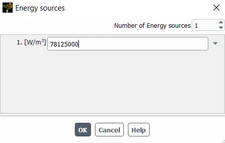
The heat generated is calculated using the formula = Power/volume in this case the volume of the enclosure is 8mm*8mm*1mm = 62*`10^-9``mm^3` and the Power is 5W.
After applying we get 78125000`W/(m^3)`
Post-processing
CFD post
A plane is created along xy and zx and the temperature distribution is graphed
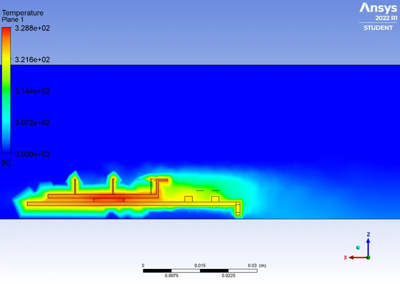
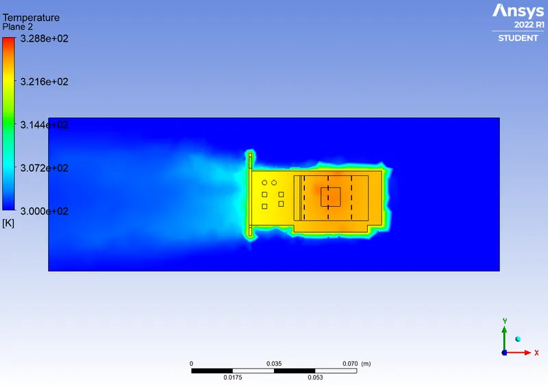
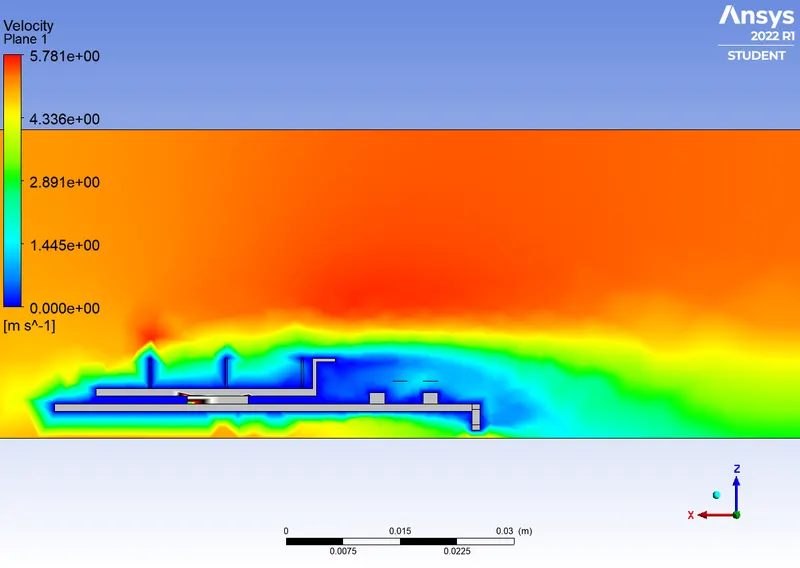
Converged at 136 iterations
Maximum heat:328.8K
Refned Mesh
The processor, fins and the base are where the convection takes place. So the mesh is refined there to 1mm.
No of elements : 434453
graphic car refinment : 0.65mm
Enclosure refinement: 5mm
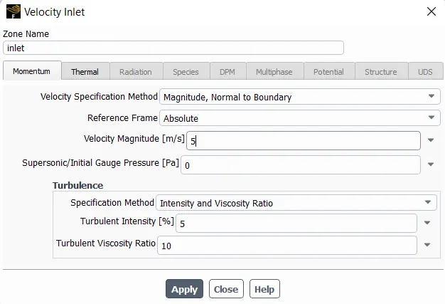
Inlet velocity - 1ms
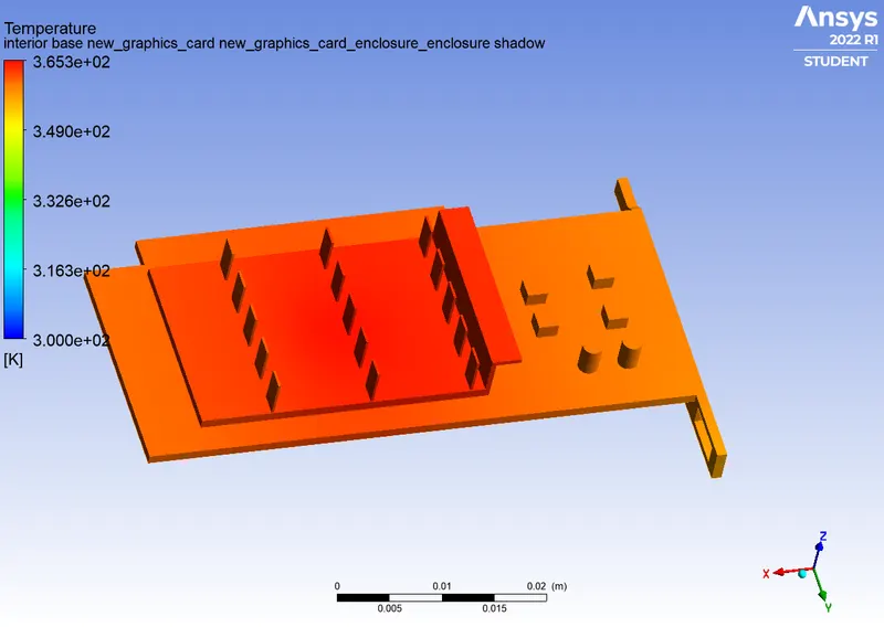
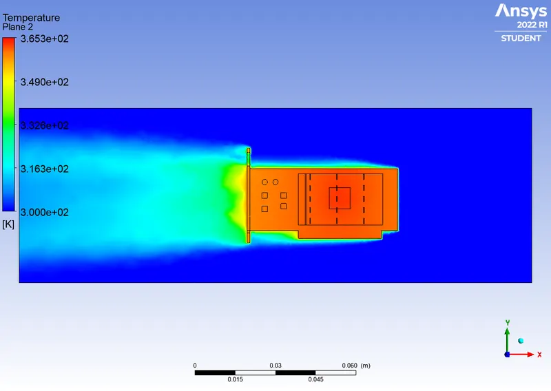
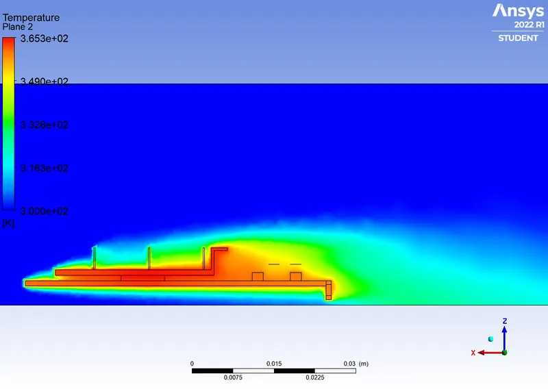
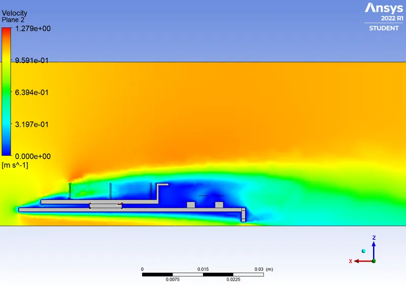
Maximum heat:365.3K
Inlet velocity : 2.5
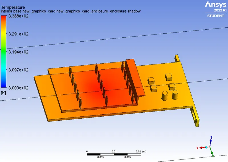
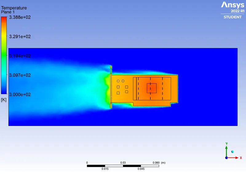
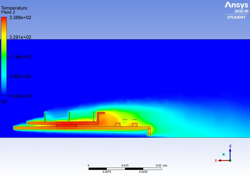
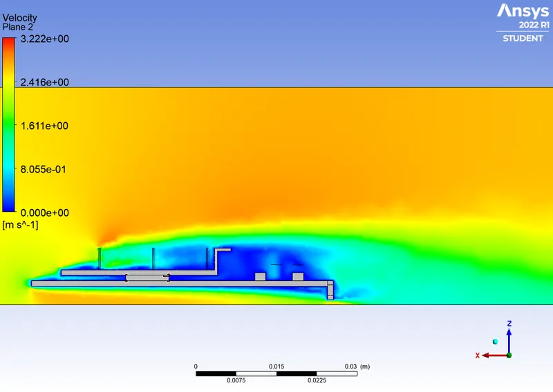
Maximum heat:338.8K
Inlet velocity : 5ms
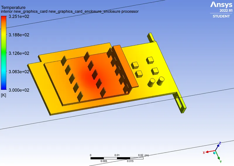
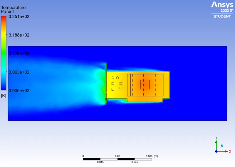
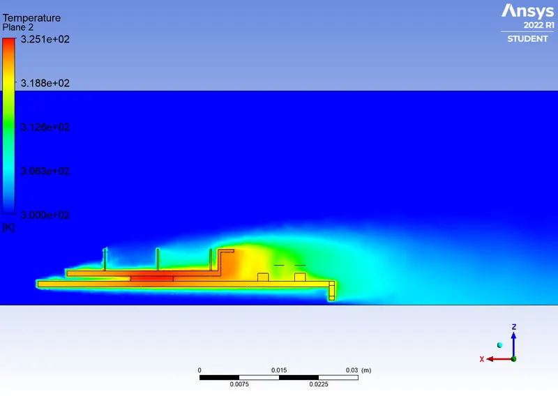
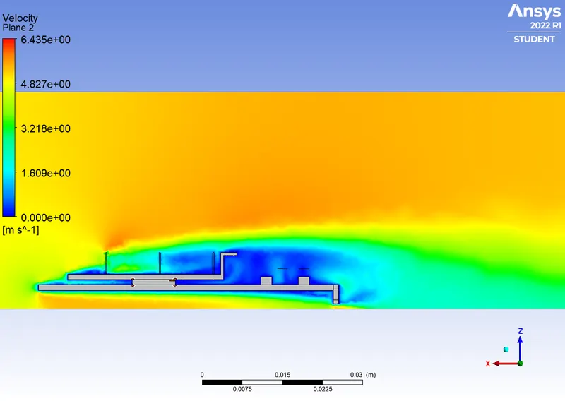
Maximum heat:325.1K
Animation
Both the animations were run for an inlet velocity of 5m/s
Refined mesh
Base mesh
Inferences
As the mesh size is increased, more iterations are needed to converge but the result gets closer to experimental data.
Conclusion
Thus a steady-state conjugate heat transfer analysis on a model of a graphics card for the multiple cases.