Week 6 - CHT Analysis on a Graphics card
Aim- To perform a steady state conjugate heat transfer analysis on a model of graphics card.
Select an appropriate material for simulation.
Mesh the geometry with a desirable combination and explain the mesh setting used on this model.
Simulate the result by varying bthe velocity of v = 1m/sec to v = 5 m/sec.
Find the maximum temperature and heat transfer coefficient obtained by the processor.
To prove the simulation has converged with image and plots.
Identify the potential hot spots .
#) Procedure-
1) First we have to import the geometry of the graphics card that is provided. Then we have to modify the geometry by the tools in spaceclaim.
2) Then we import the geometry in the mesh . Mesh the model using proper inflation layers and proper face sizing.
3) Open fluent setup0 and perform steady state conjugate heat transfer analysis.
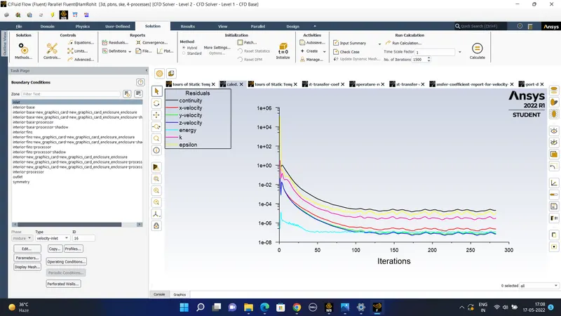
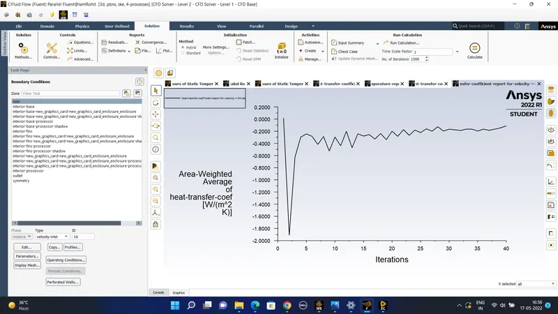
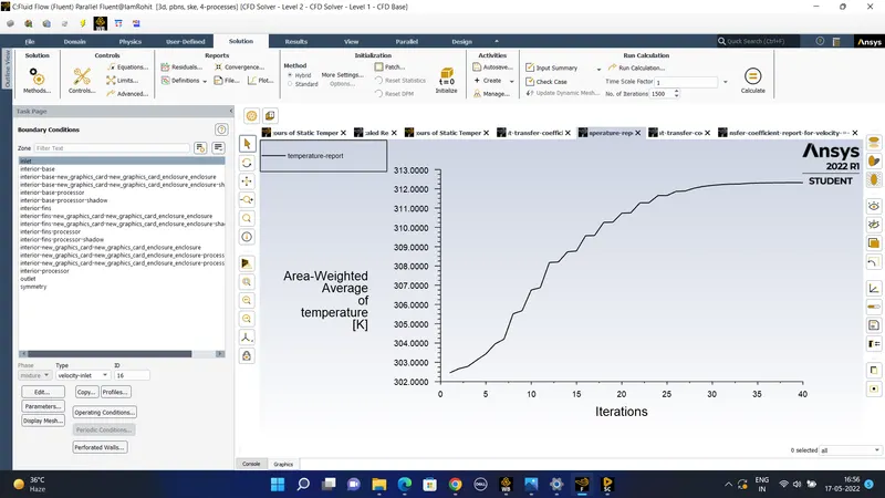
4) then we look for the convergence of the above solution that the simulation has achieved convergence . with appropiate plots .
#) Conjugate heat transfer - The Conjugate Heat Transfer (CHT) analysis type allows for the simulation of heat transfer between solid and fluid domains by exchanging thermal energy at the interfaces between them. Typical applications of this analysis type exist as, but are not limited to, the simulation of heat exchangers, cooling of electronic equipment, and general-purpose cooling and heating systems. The physics of CHT is used in many heat exchanger problems like the HVAC system and electronic component design.his model, based on a strictly mathematically stated problem, describes the heat transfer between a body and a fluid flowing over or inside it as a result of the interaction of two objects. The physical processes and solutions of the governing equations are considered separately for each object in two subdomains. Matching conditions for these solutions at the interface provide the distributions of temperature and heat flux along the body–flow interface, eliminating the need for a heat transfer coefficient. Moreover, it may be calculated using these data.
Spaceclaim geometry setup - At the starting of the simulation process the made up geometry of the graphics card which also encloses the geometry . The various component included in the geometry are base , fins , processor , enclosure and other components.
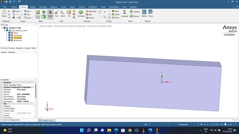
#) THe different components are represeted as the following in the spaceclaim-
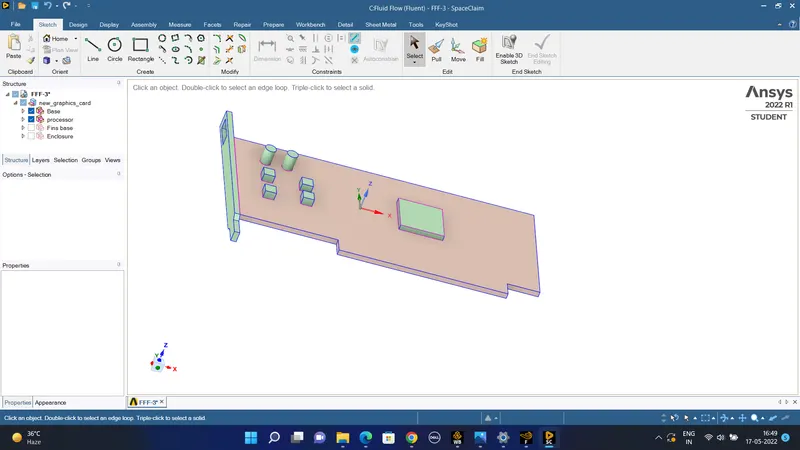
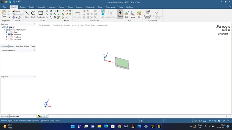
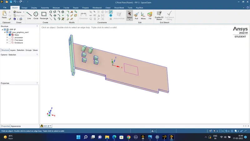
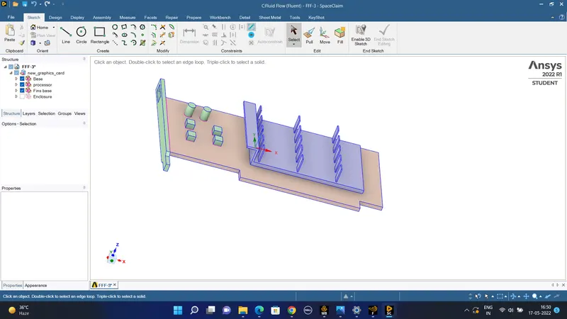
The geometry and flow domain consists of a flat circuit board with a heat generating electronic circuit board in which if the processor is running dueto the electricity flow into it and due to resistance heat is generated . Heat is conducted through the source the board mounted on it and the fins attached to it. When the fins are used it serves the purpose of conductinh heat and when air is flowing on it the heat is getting convected out of it due to the air flow. It causes simultaneous flow of heat from the hot component to heat the surrounding air flowing over it with a range of velocity from v = 1 m/secd to v = 5 m/sec.
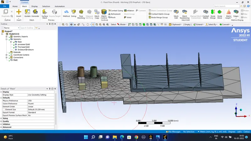
#) Meshing - The first method of meshing is of the geometry is off to give name to the sections or the surface and components
#) baseline method - In baseline meshing two inflation layers are being added with a total thickness of the 0.4 mm were used to give the idea of the y+ value inflaion layer for final simulation mesh is considered.
It is difficult to calculate the Reynolds number for this problem because for these the characteristics length can not be calculated. But we know that the turbulence model we need the value of y+ to be greater than the 5 to get desirable results
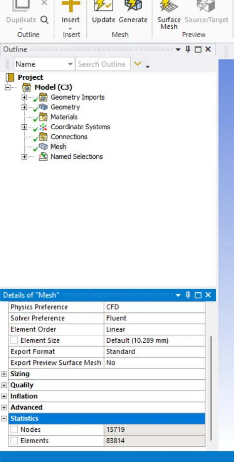
For the baseline model we are using the automatically generated default mesh which is having the element size of the mesh as the standard 10 mm of length . Near the processor the mesh is little finer.
#) Then the same geometry is imported in the solver-
We have to give the different components of the graphics card of different material to it.
The processor is predominantly made up of the silicon-based material whereas the base of the component is made up of the material of the copper and the fins that are att6ached on the top of it are to be made up of aluminum.
we are using the seady state solver the solution method uses the coupled scheme would be used.
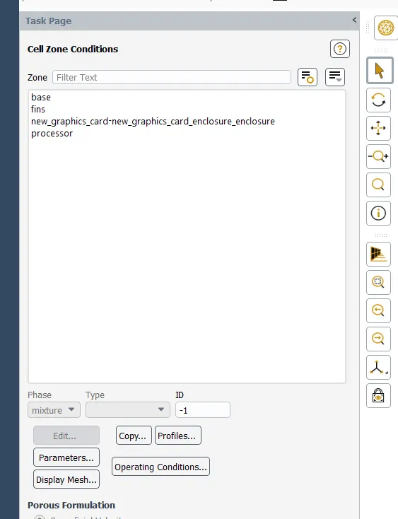
for V = 1 m/sec the cell zones created are as follows-
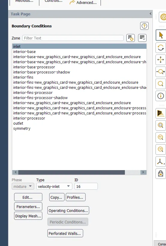
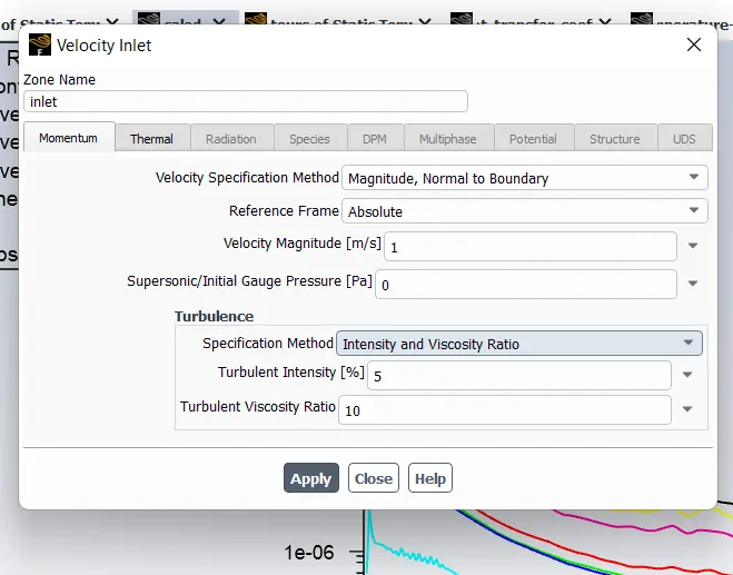
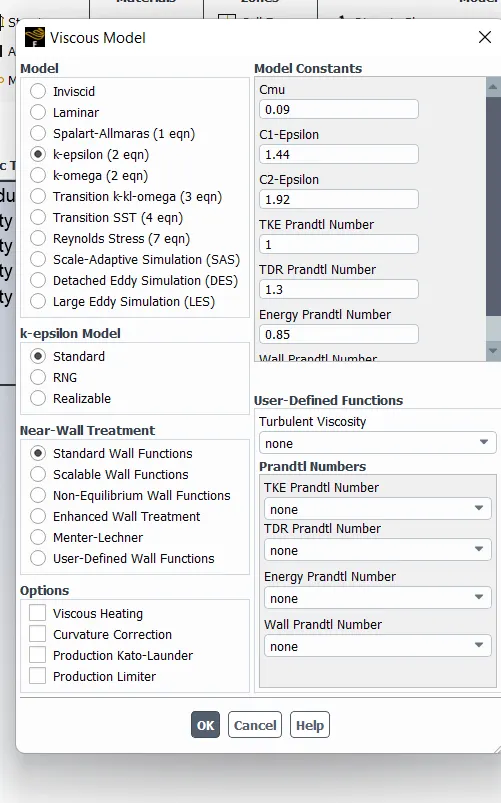
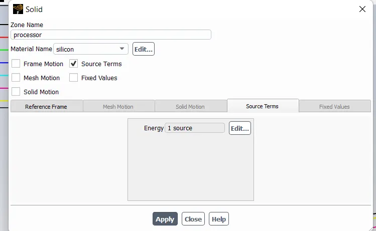
The heat produced by the graphics card source is of power = 64*10^-9 m^3.
Heat generated = 10/(64*10^-9) =
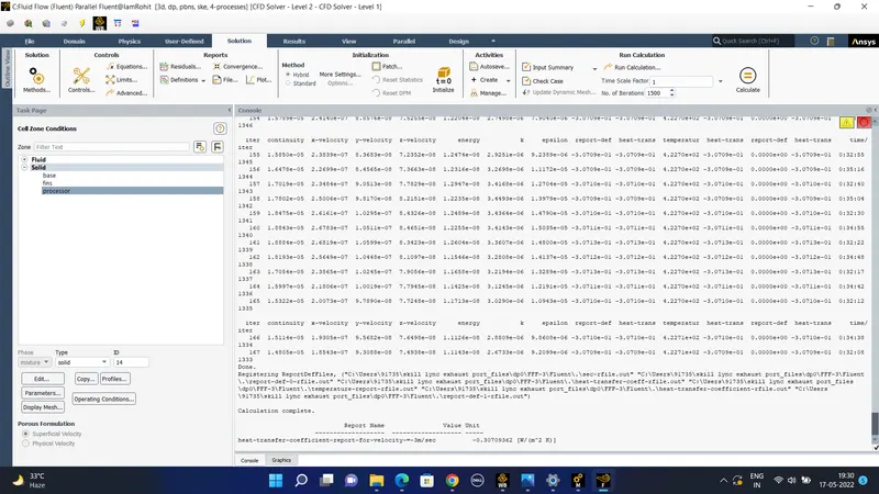
The outcomes obtained for these mesh using the velocity v = 1 m/sec
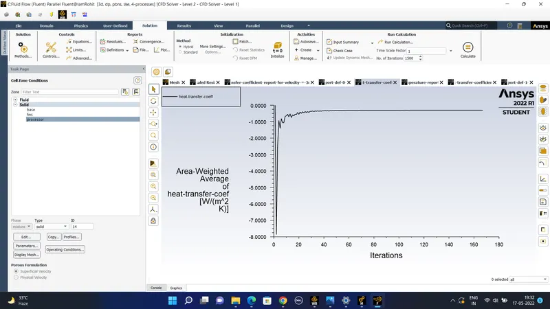
#) In this case we give the velocity of the air at the inlet as v = 3 m/sec.
3) in the second case we modified the mesh by giving more elements in the face of the face of the circuit board is to be meshed again by using the face selection tool and reducing the element size of the base to be of 1 mm and the fins on the top of the processor is divided into elements of size of 2 mm.
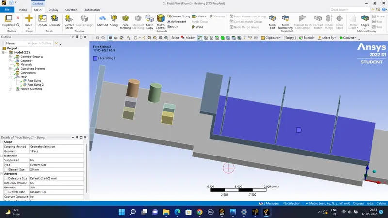
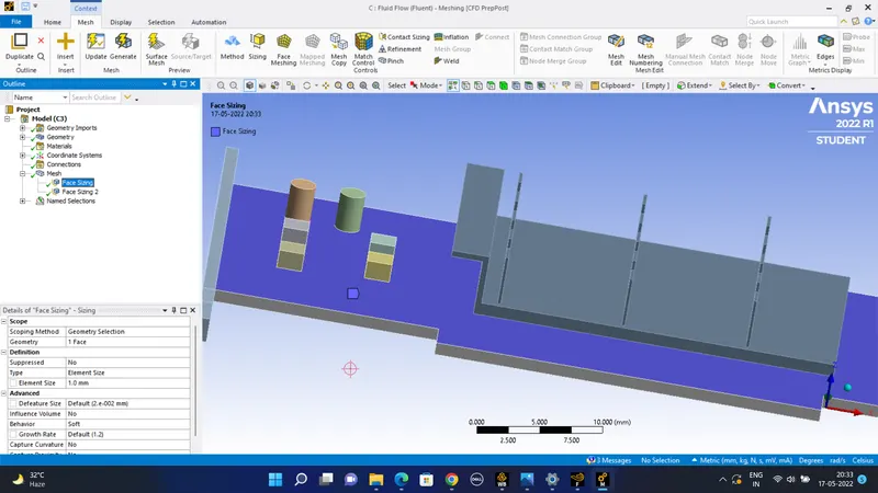
The mesh looks like this-
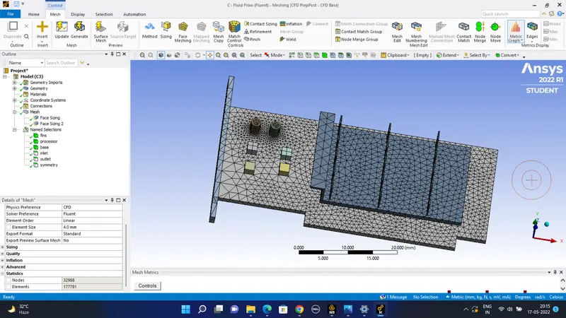
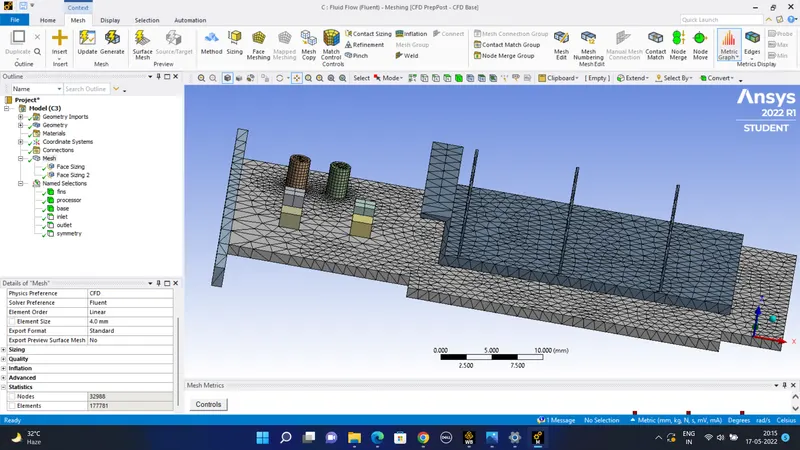
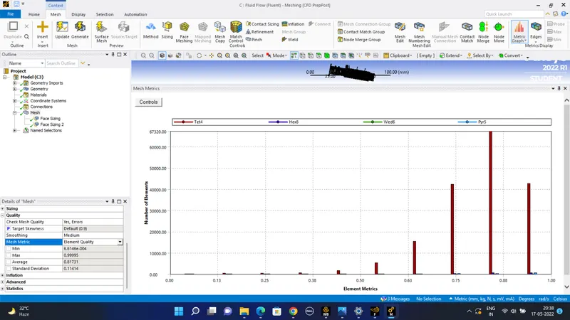
#)The mesh metrix gives the quality of the mesh -
The results obtained are as follows-
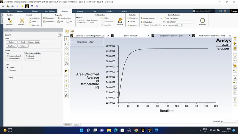
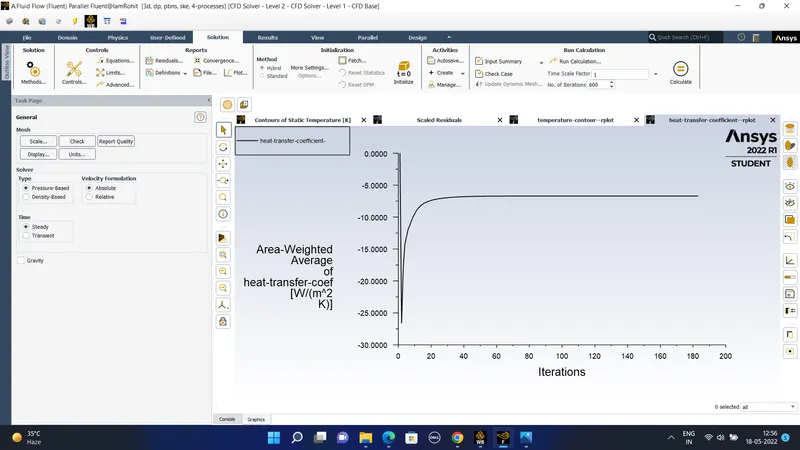
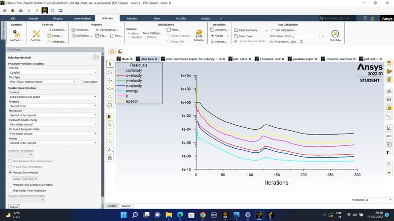
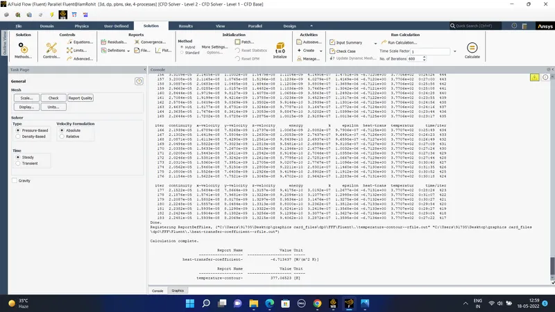
#) So the heat transfer coefficient is of 6.713 W/m^2k. and the temperature is of 377k
3) In this case we refine the mesh further and the inlet velocity of the air is increased o the velocity v = 5 m/sec.
The new finer mesh obtained by reducing the element size is as follows-
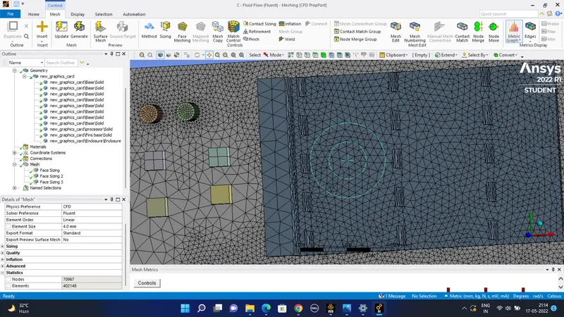
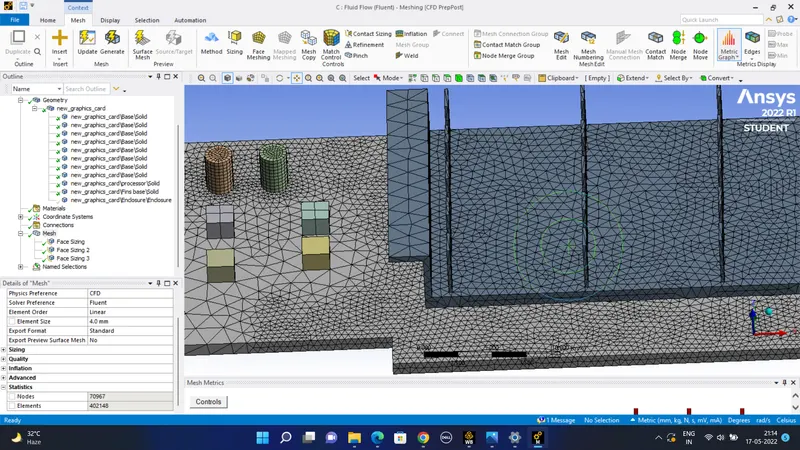
The mesh metrices are shown below as -
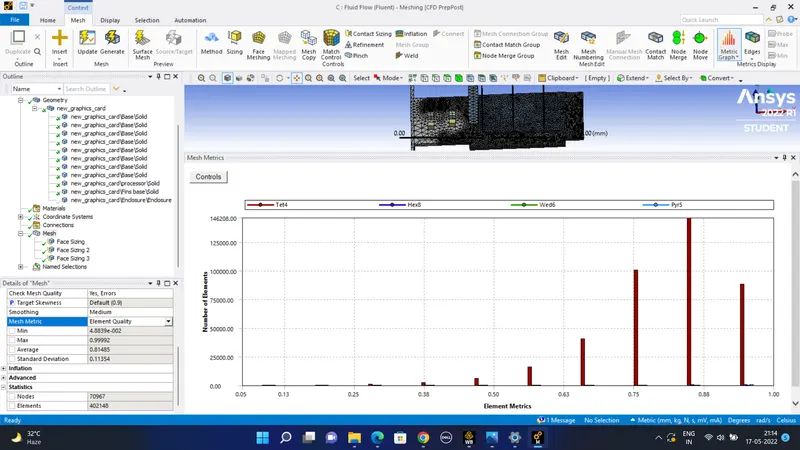
For the velocity v = 5 m/sec we get the following outcomes as follows-
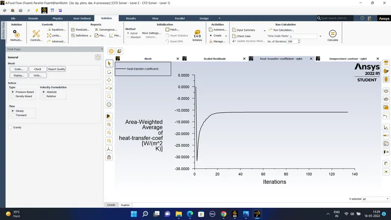
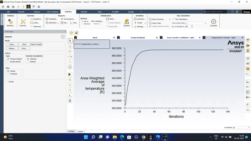
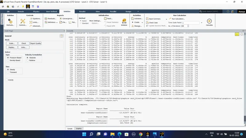
The result value of the heat transfer coefficient and the temperature of the processor obtained is -
The temperature contours obtained for the velocity of ambient air to be equal to v = 5 m/sec.
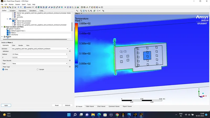
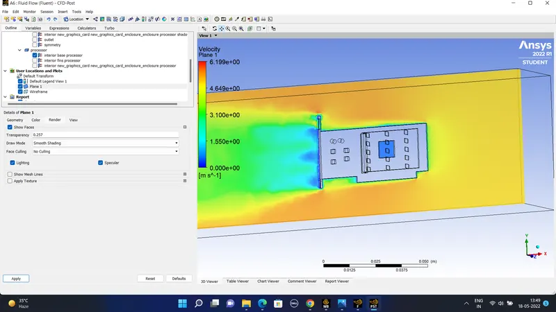
#) The results obtained from the mesh dependency study was carried out by three different mesh the first one was the default generated mesh , the second one was the modified mesh and the third mesh contained the 402145 elements .
Number of nodes number of elements temperature(k) heat transfer coefficient
Mesh 1 - v= 1 m/sec 15719 83814 390.06 - 4.122
Mesh 2 - v= 3m/sec 32988 177781 377.06 -6.713
Mesh 3 - v = 5m/sec 70976 402145 363.79 -10.915
#) Conclusion-
So as the mesh is refined from mesh 1 to mesh 3 where we increase the number of the elements we get the temperature much less of the processer because the velocity is also increased so it takes away the bulk of heat and reduces the temperature of the processor and the heat transfer coefficient is increasing as the velocity is increased so from the edges of the processor more amount of heat is taken out which results into higher heat transfer coefficients.