Week 6 - CHT Analysis on a Graphics card
Conjugate Heat transfer analysis over a graphics card
| Table of contents |
| ->Aim |
| ->CHT(Conjugate Heat Transsfer) |
| ->Procedure |
| ->Fluent Settings |
| ->Results |
| ->Inferences and conclusions |
Aim:
In this challenge,we will perform a steady-state conjugate heat transfer analysis on a model of a graphics card. We also perform the following tasks:
- To run the simulation by varying the velocity from 1m/sec to 5m/sec for at least 3 velocities and discuss the results.
- To find out the maximum temperature and heat transfer coefficient attained by the processor.
- To drove that the simulation has achieved convergence with appropriate images and plots.
- To identify potential hotspots on the model.
CHT(Conjugate Heat Transfer):
Conjugate heat transfer is a type of heat transfer analysis between solids and fluid(s). This type of heat transfer includes both convection (between fluids) and conductive (between solids) heat transfer, as well as both forced and natural convection. Common applications and use cases of this thermal simulation type include electronics cooling, heat exchangers, industrial machinery,etc.
In most cases, heat transfer in solids, if only due to conduction is given by fourier's law of heat conduction which describes heat flux as `q=-knablaT`, whereas for a time-dependent problem, the temperature field in an immobile solid verifies the following form of the heat equation:
`rho*underset(p)(C)*(delT)/(delt)=nabla.(knablaT)+Q`
In a fluid, due to the fluid motion, three contributions to the heat equation are included:
- The transport of fluid implies energy transport too, which appears in the heat equation as the convective contribution. Depending on the thermal properties on the fluid and on the flow regime, either the convective or the conductive heat transfer can dominate.
- The viscous effects of the fluid flow produce fluid heating. This term is often neglected, nevertheless, its contribution is noticeable for fast flow in viscous fluids.
- As soon as a fluid density is temperature-dependent, a pressure work term contributes to the heat equation. This accounts for the well-known effect that, for example, compressing air produces heat.
Heat transfer in fluids and solids can also be combined to minimize heat losses in various devices. Because most gases (especially at low pressure) have small thermal conductivities, they can be used as thermal insulators. In areas which involve cooling of components like turbine blades and transfer of heats across media, CHT is necessary to accurately model the system.
In a graphics card, the processor is like the brain of the computer. Since it consumes power and it runs to process data and store files and so on, sufficient analysis need to be done so as to make sure whether the processor with the given material that it is made of operates in optimum condition. Sufficient cooling techniques are employed in supercomputers which can process trillions of data in a second and hence this topic needs sufficient attention.
Procedure:
The procedure involves importing the file in spaceclaim and constructing an enclosure after which the bodies are shared so that only one interface exist between any two components. Note that a graphics card consists of processor, fin and a pcb board.
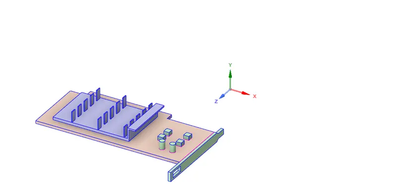
Enable share of objects so that there exists only one common interfaces instead of two.
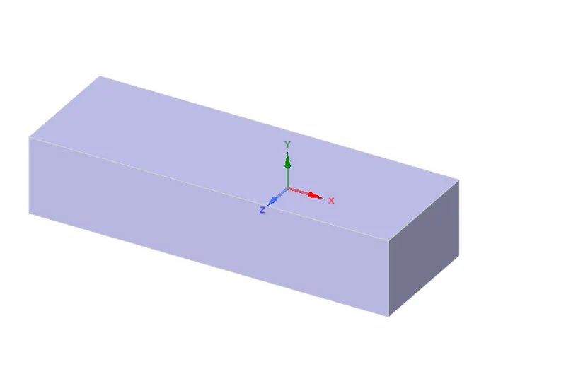
Finally, add an enclosure so that we treat the cells as a fluid zone and close spaceclaim.
This is followed by meshing the geometry file and applying sufficient body sizing to the components.

The mesh of the graphics card looks like this:
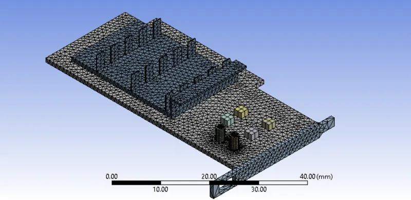
The mesh quality distribution is shown. It shows that the average mesh quality is 0.82 which is acceptable for this standard of problem.

Once this step is done, close meshing and update the mesh. This will load the mesh file into the solver.
Fluent Settings:
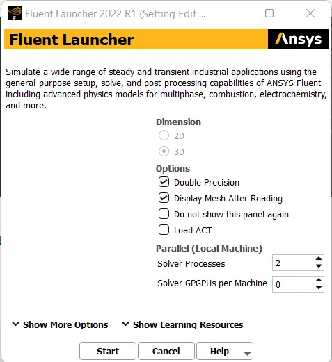
Create a new material for silicon under the materials tab.
Define the cell zones in fluent.
The processor should be treated as solid.
Once done, enter the following values in fluent on appropriate tabs
Inlet velocity- 1/3/5 m/s
Materials uses throughout- Silicon
Viscous model- k-epsilon standard
Energy equation- turned on
Source term- Processor
Value:
Assuming power consumption of 10W, volume of the element is 64 `mm^3`
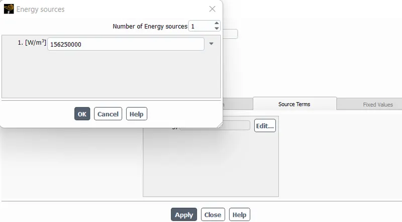
The reason to provide the source term is because processor generates heat as a result of processing volumes of data and hence the CHT analysis is done.
The solution is run for 300 iterations but the results converged quickly for all the cases because of the use of viscous model.
Post processing is done by exporting sufficient data like heat transfer coefficient from fluent to CFD-Post.
Results:
For Velocity = 1m/s
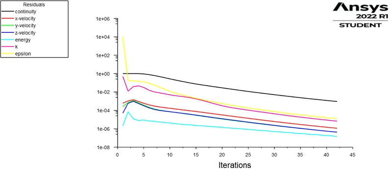
Convergence plot for residuals
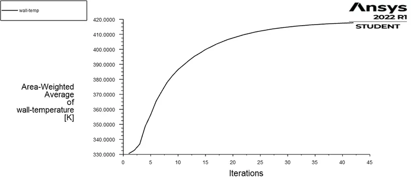
Convergence of Average wall temperature
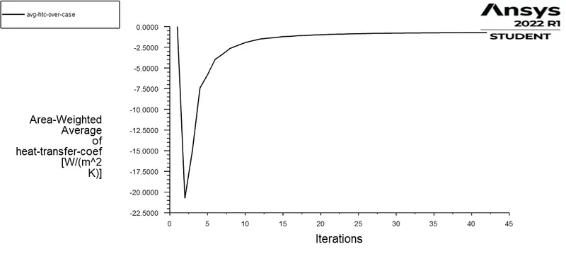
Convergence of Average heat transfer coefficient
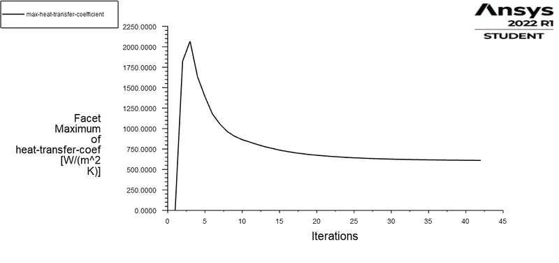
Convergence of maximum heat transfer coefficient

Values of the monitor parameters
(-ve sign indicates heat transfer in opposite direction)
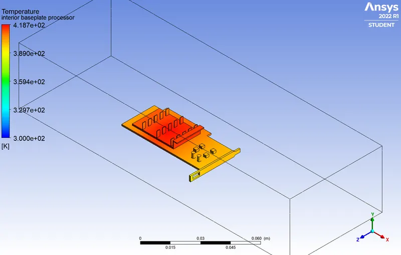
Contours of temperature over the entire graphic card
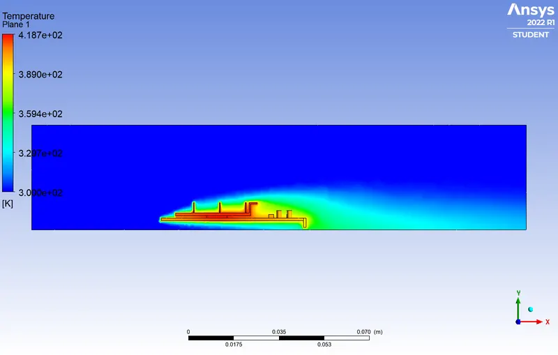
Contours of temperature at a sectional plane
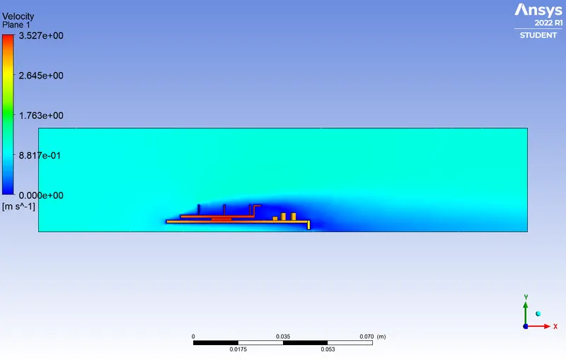
Contours of velocity at a sectional plane
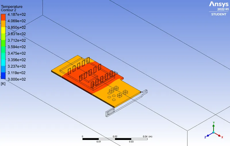
Potential hotspot in the processor-fin-baseplate assembly
For velocity=3 m/s
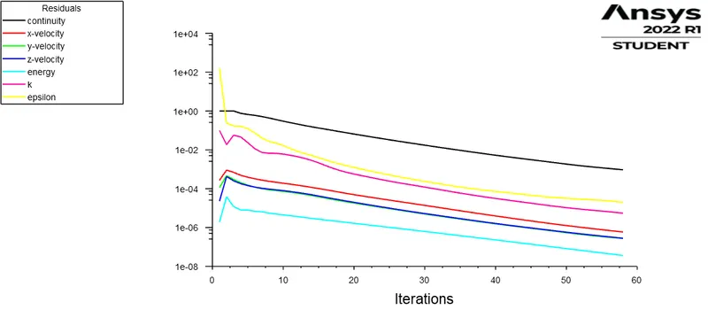
Convergence plot for residuals
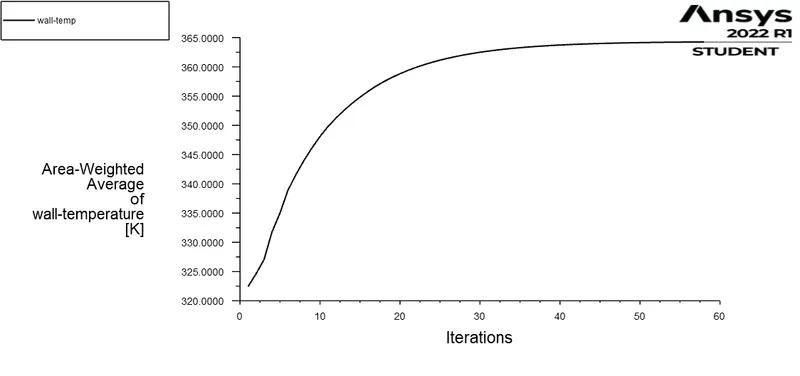
Convergence of Average wall temperature
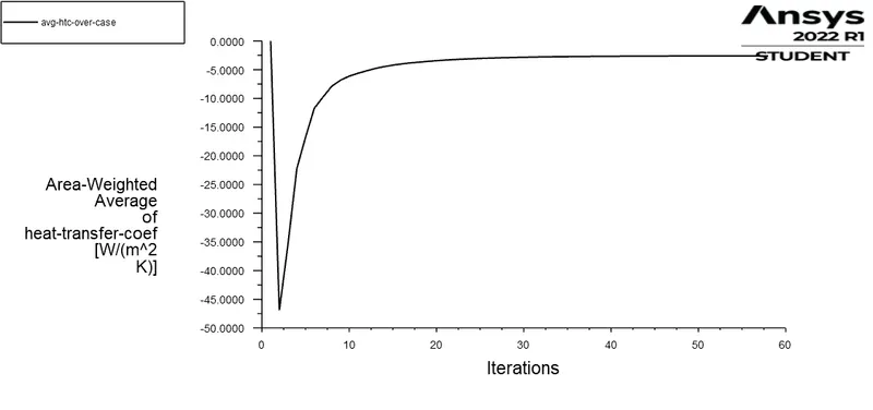
Convergence of Average heat transfer coefficient
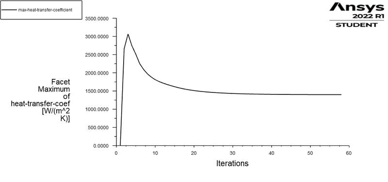
Convergence of maximum heat transfer coefficient

Values of the monitor parameters
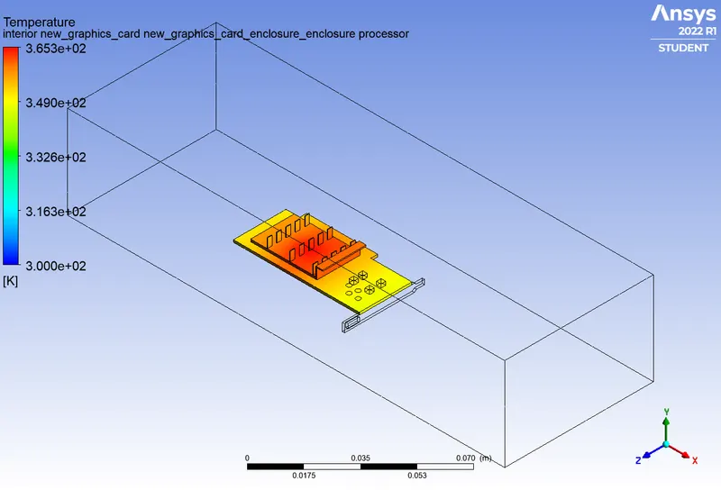
Contours of temperature over the entire graphic card
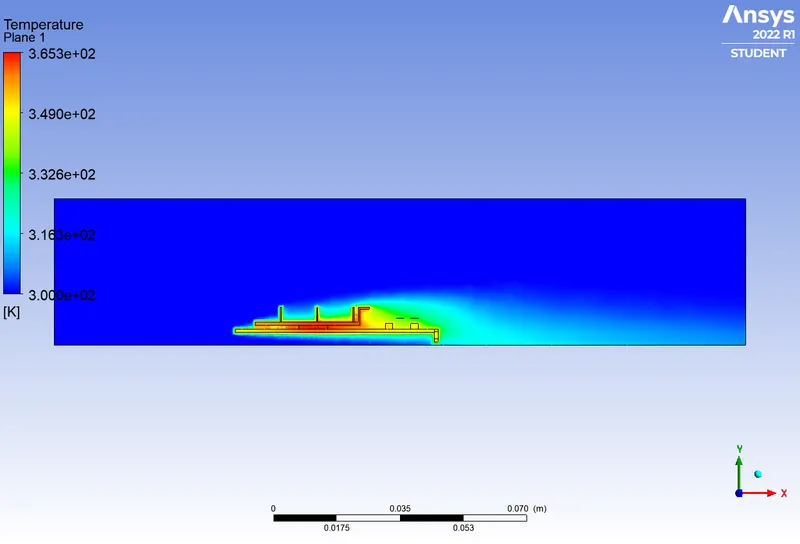
Contours of temperature at a sectional plane
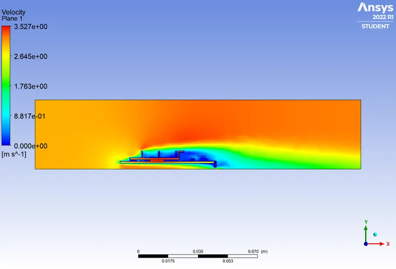
Contours of velocity at a sectional plane
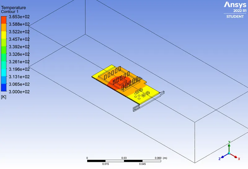
Potential hotspot in the processor-fin-baseplate assembly
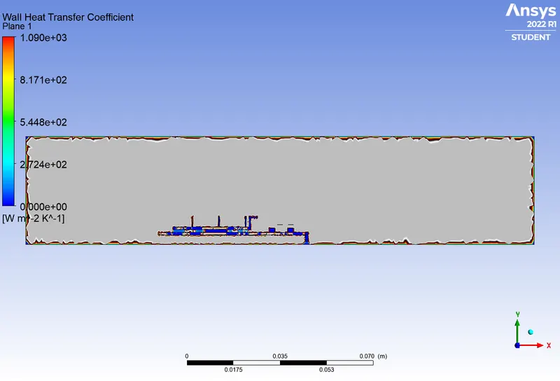
Variation of wall heat transfer coefficients
For velocity=5 m/s
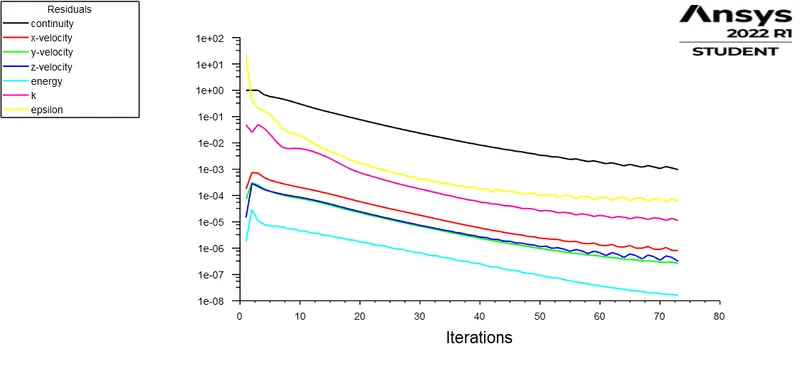
Convergence plot for residuals
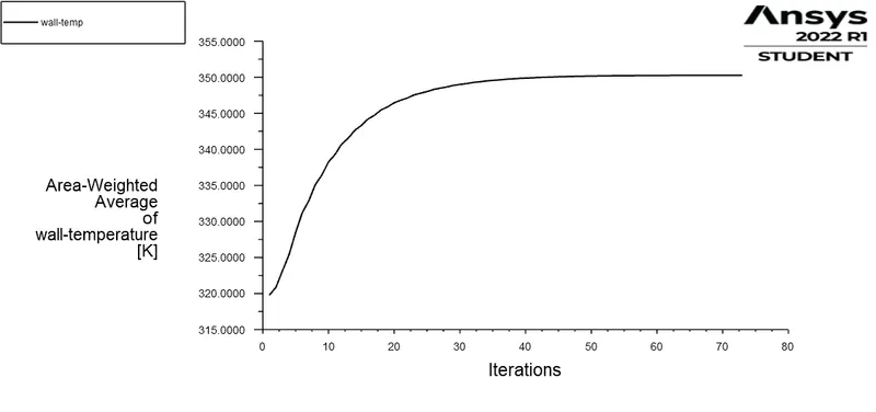
Convergence of Average wall temperature
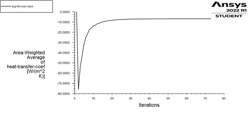
Convergence of Average heat transfer coefficient
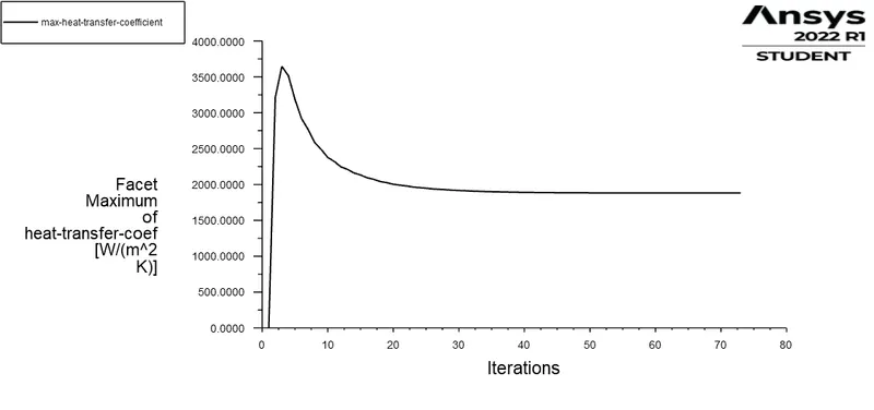
Convergence of maximum heat transfer coefficient

Values of the monitor parameters
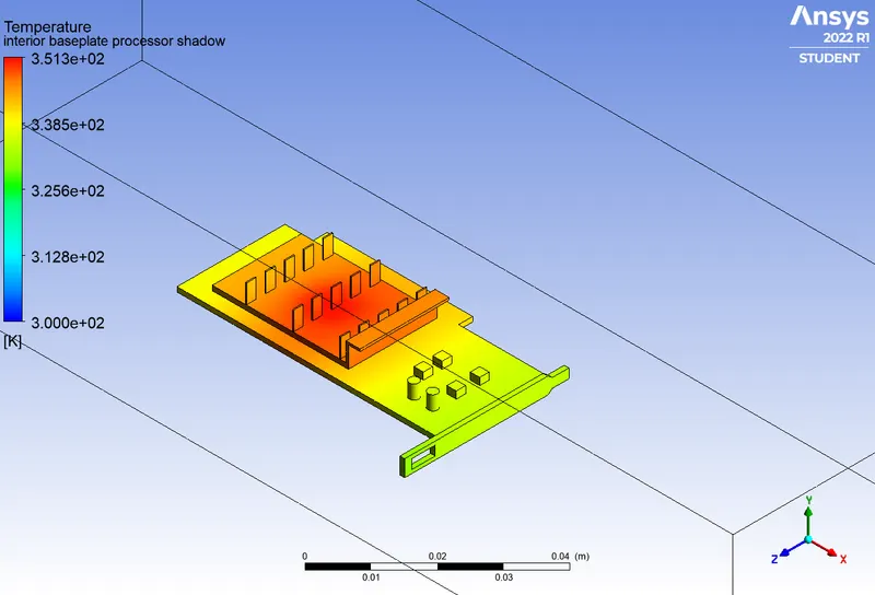
Contours of temperature over the entire graphic card
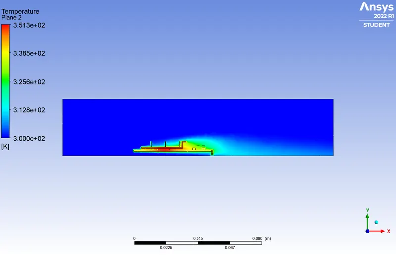
Contours of temperature at a sectional plane
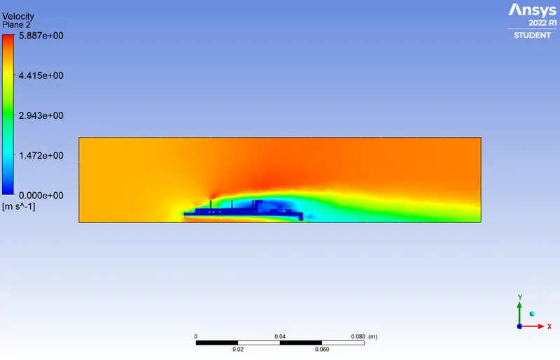
Contours of velocity at a sectional plane
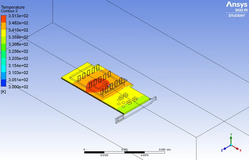
Potential hotspot in the processor-fin-baseplate assembly
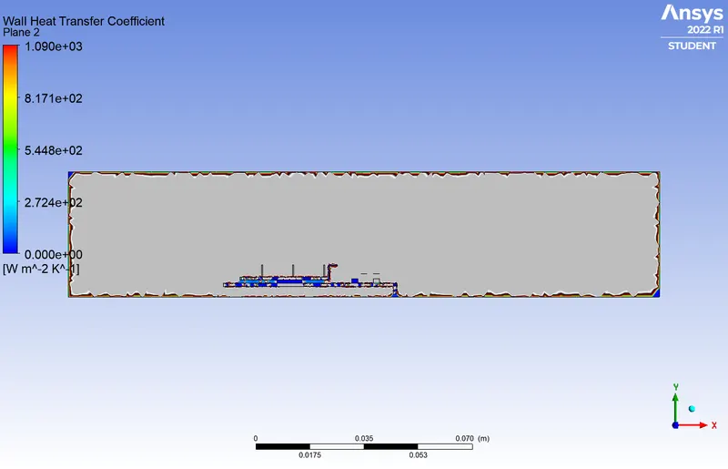
Variation of wall heat transfer coefficients
Inferences and conclusions:
1. As we can see from the above contours, for air with higher velocity, convection occurs much faster and the wall heat transfer coefficient is higher for higher velocity flow(magnitude only)
2. As the velocity of air increases, the wall temperature becomes lower due to better convection at higher speeds.
3. Looking at the hotspots in the three cases, we can also infer that the temperature distribution over the entire graphics card is much more pronounced at higher velocities due to better convection.
4. Thus we have performed the CHT analysis over a graphics card with varying velocities.