Week 6 - CHT Analysis on a Graphics card
In this simulation, we shall be performing a study of conjugate heat transfer using steady state conditions on a CAD model of a graphics card.
The various steps involved shall include performing necessary steps in CFD SpaceClaim, to make the geometry complacent for further analysis, meshing individual components according to our area of interest, learning variation in results as compared to some baseline mesh and inferences from post processing.
Introduction and theory:
Owing to huge demand of electronic components, and advancements leading to packing of more power in a smaller space has led to the inevitable problem of heat dissipation. In this challenge, we shall try to analyse the heat generated in the core area (processor) of a graphics card and its transfer onto other components of the card. The transfer rate shall of course be driven by the materials chosen for various components. Keeping that into perspective, I have searched and selected 4 different group of materials to graphic card. Before we discuss about the materials, let us now understand the components of a graphic card.
Parts of GPU:
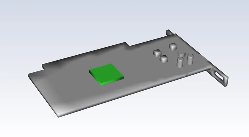
The base and core component of a GPU, is the processor which could be though of as the brains of the GPU, here all the core computing takes place. This decides the power and speed of the GPU, so naturally, this is where the heat shall be generated. Thus, we shall be providing a source term into our equations to this zone.
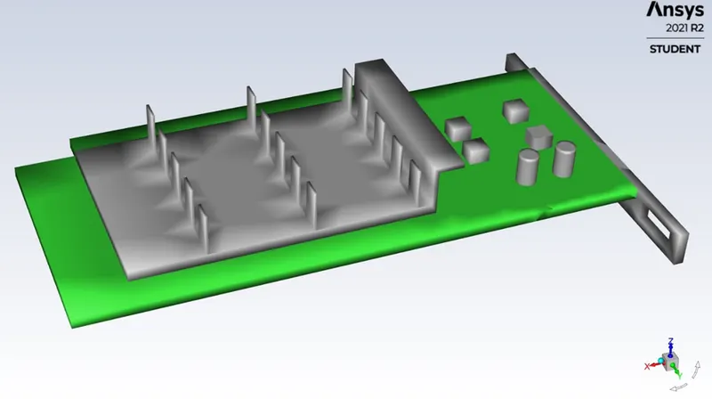
Next comes the processor circuit board, one could maybe call it a motherboard of the graphics card.
This is where the processor is seated and housed.
We have capacitors, were energy storage, filtration, bypass and decoupling take place.
We have VRAMS, VRAM is the portion of RAM that is specifically dedicated to processing graphics-related tasks. VRAM stores all of the image and graphics data that is shown on the computer's display. This helps ensure that the display of graphics is executed smoothly and evenly.
Next, we have connector, this is a bracket which is fixed to the housing of PC, all external connections are done in here.
finally, we have heat sink and heat sink fins, this sub-component is placed directly in contact with the processor, generally via a thermal paste, so enhance heat generated in processor.
Heat sink increases the heat transfer area of processor so dispel most of the heat generated efficiently without causing processor to overheat thereby saving it from getting messed up. This is the most critical sub-component regarding our challenge as this is where heat transfer shall be studied prominently.
Source Term:
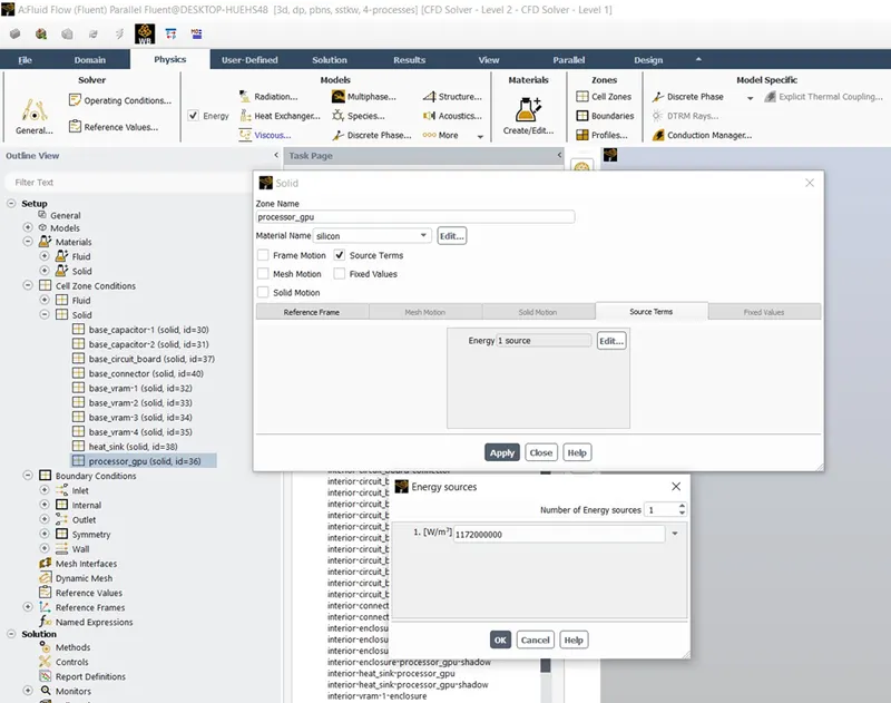
Method of arriving at the source term is thus, sifting through some global GPU sites, we see various TDPs (thermal Design Power) for graphic cards. I’ve chosen a TDP of 49 watts which seems to ben the normal running TDP for most everyday use GPUs.
The geometrical size of processor here is about 64 cubic meters, thus the source term can be calculated to be about 7.65e8 watts per cubic meter.
Materials used in Graphics Card:
Aluminium is used for Heat sink, heat sink fins and the connector.
Fr-4 material, which is a thermally insulating material, is used as the pcb
Silicon is used for VRAMS and processor.
Nickle is used for capacitor.
Properties of materials.
Aluminium:
Density = 2719 kg per cubic meter
Specific heat = 871 joules per kg kelvin
Thermal conductivity = 202.4 watts per meter kelvin.
Fr-4:
Density = 1850 kg per cubic meter
Specific heat = 1100 joules per kg kelvin
Thermal conductivity = 0.25 watts per meter kelvin.
Silicon:
Density = 2300 kg per cubic meter
Specific heat = 710 joules per kg kelvin
Thermal conductivity =148 watts per meter kelvin.
Nickle:
Density = 8900 kg per cubic meter
Specific heat = 460 joules per kg kelvin
Thermal conductivity =92 watts per meter kelvin.
Solving & Modelling approach
Snippets of the geometry, its Meshing are attached, a brief discussion on each snippet will throw some light.
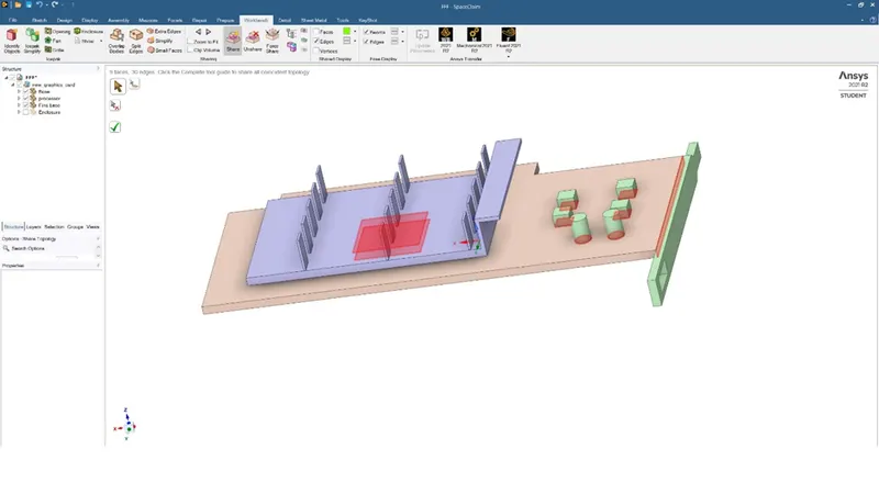
Shared topology
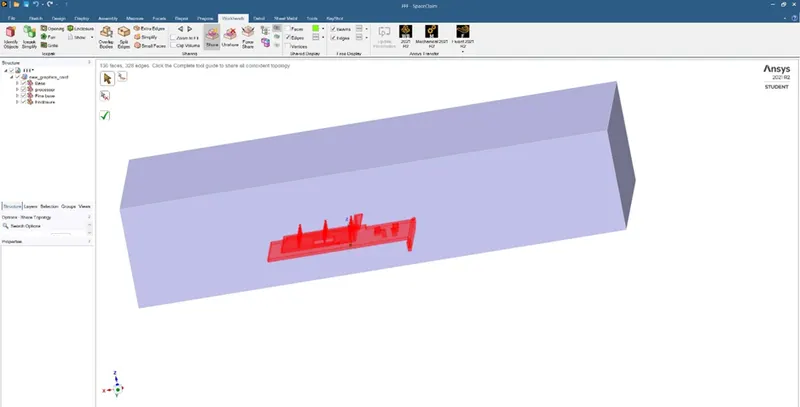
Shared topology 2
Parts of GPU:
- Capacitors
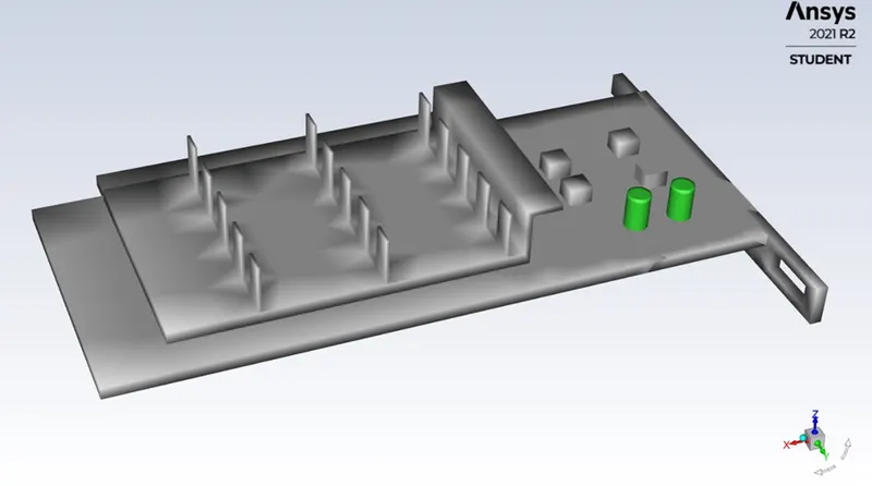
-
Connector
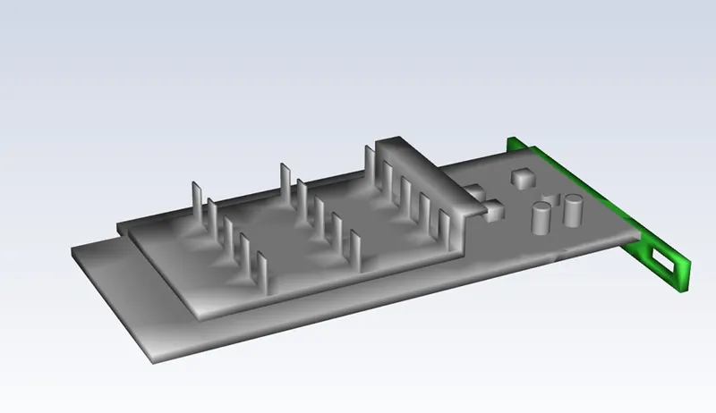
-
GPU Processor
-
PCB
-
VRAM
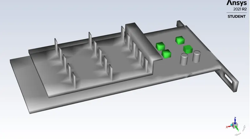
In SpaceClaim, we choose share topology from workbench. This enables connectivity between various sub-components. This Is how information gets shared and is imperative for conjugate heat transfers.
MESHING:
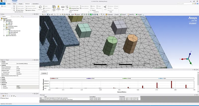
Next step is to create a mesh for the geometry.
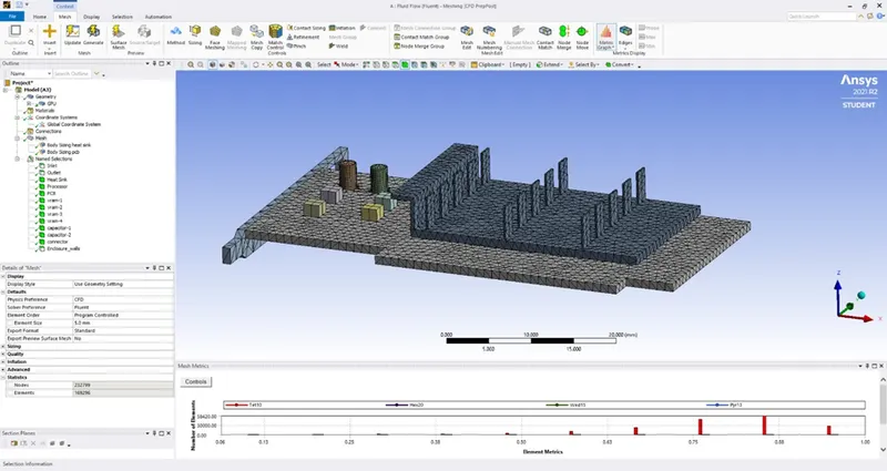
Here a size of 3 mm is given to the base mesh. We need to create refined mesh for particular sub geometry keeping the shared topology feature intact.
We also do need to keep the cell count in check.
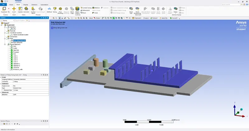
This was achieved by supressing all other parts except processor, creating body sizing of size 1 mm for the same.
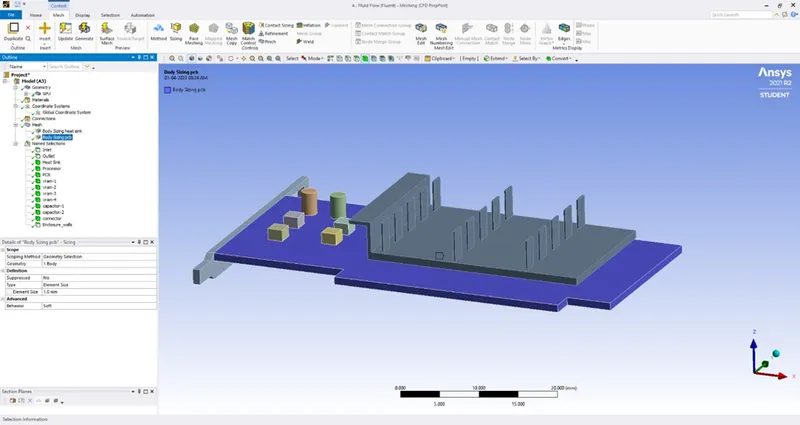
Un-supressing heat sink, creating body sizing of 1 mm. Repeat for circuit board and then for enclosure.
This way we get refinement as required for heat sink, circuit board and processor according to temperature variation in these three.
The total cell count was below 200,000.
Named selections are also important to have an understanding of interfaces between solid-solid and solid-fluid regions in fluent. These also, reduce warnings we get during loading phase in setup.
Some of the snippets to illustrate the same.
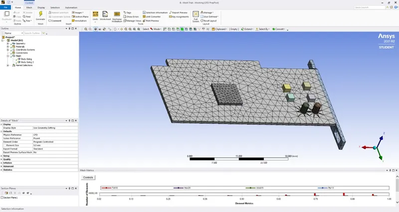
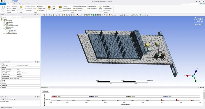
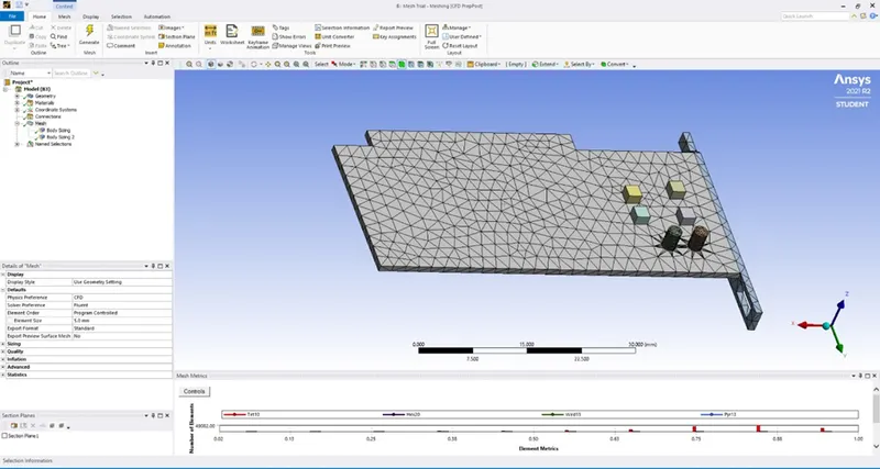
Meshing final (changed element order to linear)
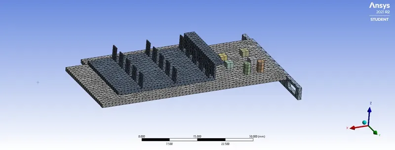
Cut view of meshing
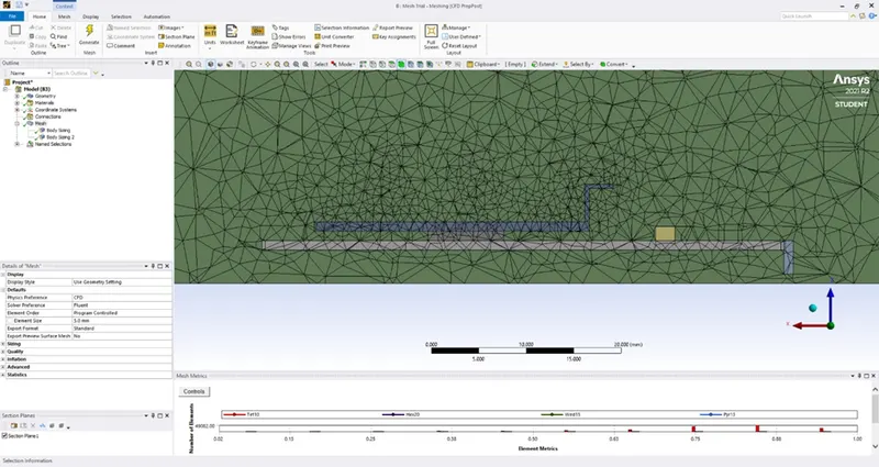
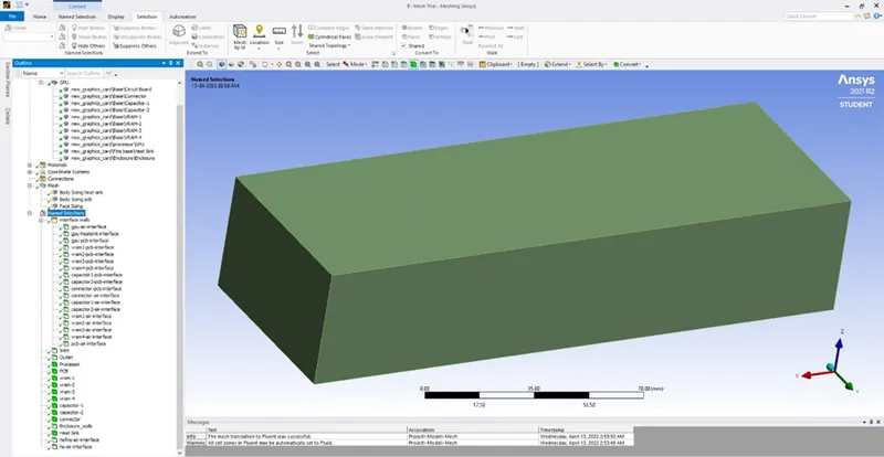
Named selection including interface names
Meshing of heat sink
Meshing of circuit board
Changed element order to linear
SETUP – FLUENT
SETUP – FLUENT
Steps to be followed in setup:
- Check energy option under models tab.
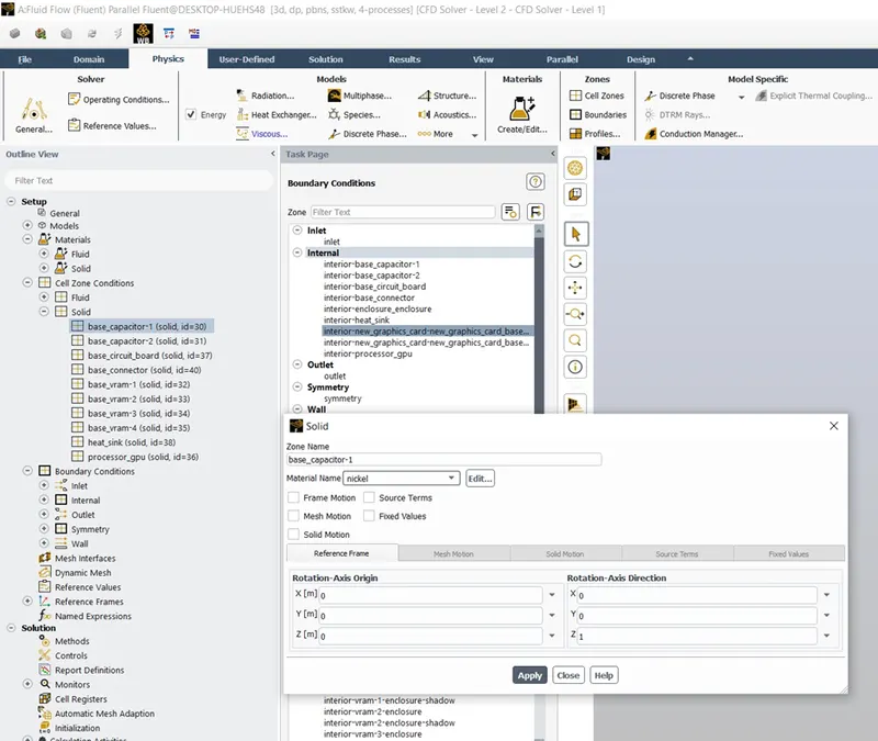
- Under materials tab, add required materials under solids tab.
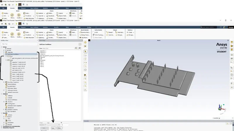
- Change all the sub-geometries, except enclosure in cell zone to type solid from fluid. This is imperative for correct analysis.
- Under boundary conditions, check for correct material selection for different boundary zones.
- For inlet boundary, give a velocity of 1,3 and 5 meters per second as the case demands.
- We have run 3 different cases with three velocities.
- For processor, under cell zones, add a source term as well as discussed above.
- Also, select k-epsilon solver for simulation.
- Run initialization and create contours of temperature on the graphics card.
- Also create reports for temperature on different sub geometries to check for temperature variation in these sub parts.
- Create plots for heat transfer coefficient at the processor walls under boundary conditions.
- Run simulation for about 200 iterations.
Capacitor material
GPU Material
Heat Sink Material
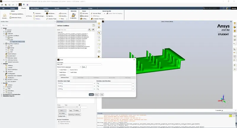
PCB
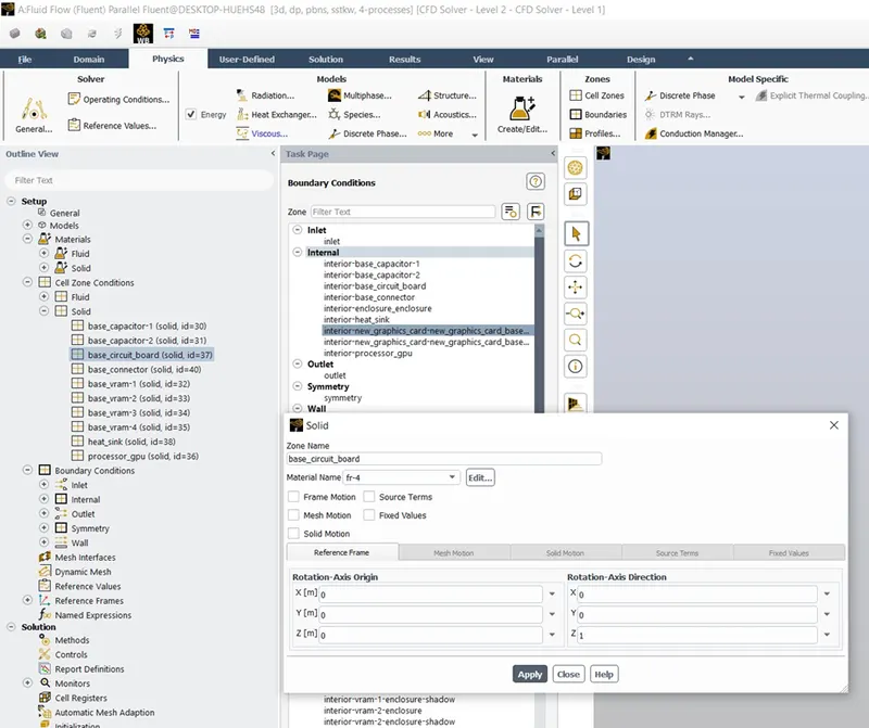
VRAM
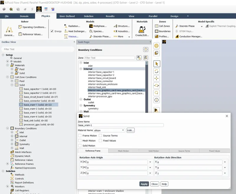
Post processing results:
Results for inlet velocity of 1 meter per second
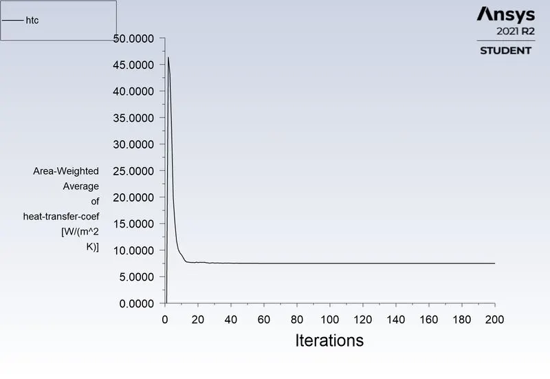
htc plot
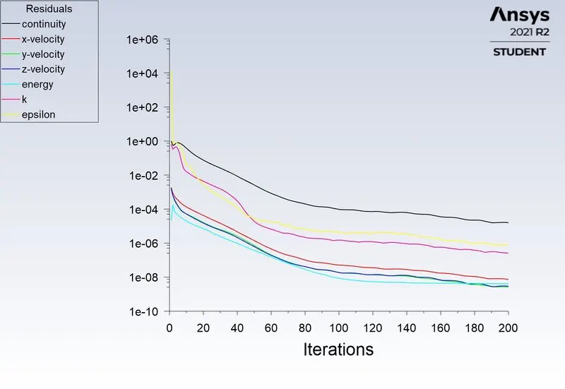
Residuals
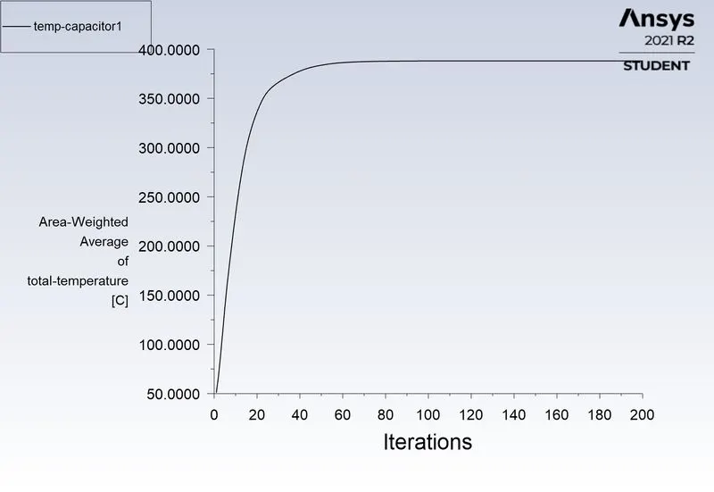
Temperature of capacitor
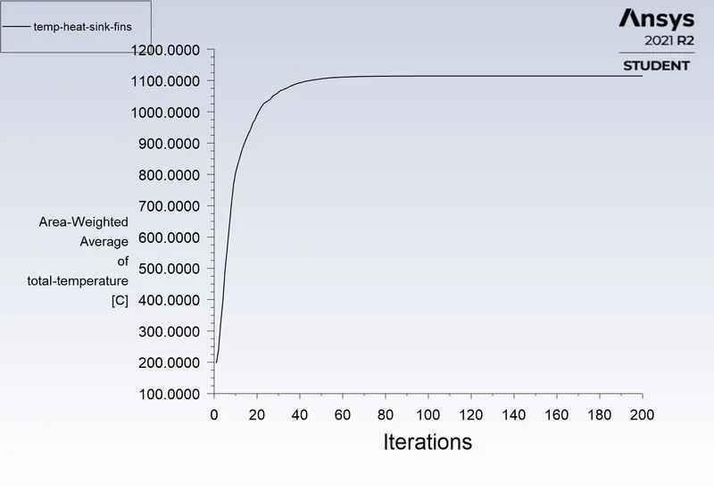
Temperature of heat sink fins
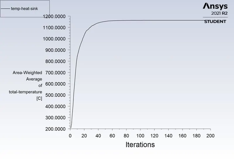
Temperature of heat sink
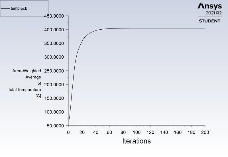
Temperature of pcb
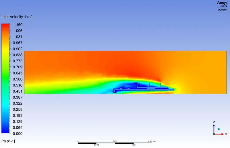
Velocity cut plane profile
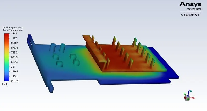
Total temperature
Results for inlet velocity of 3 meter per second
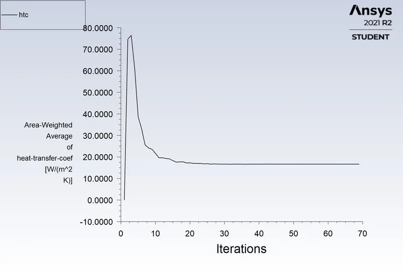
Convective heat transfer coefficient
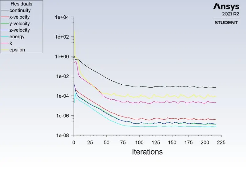
Residuals
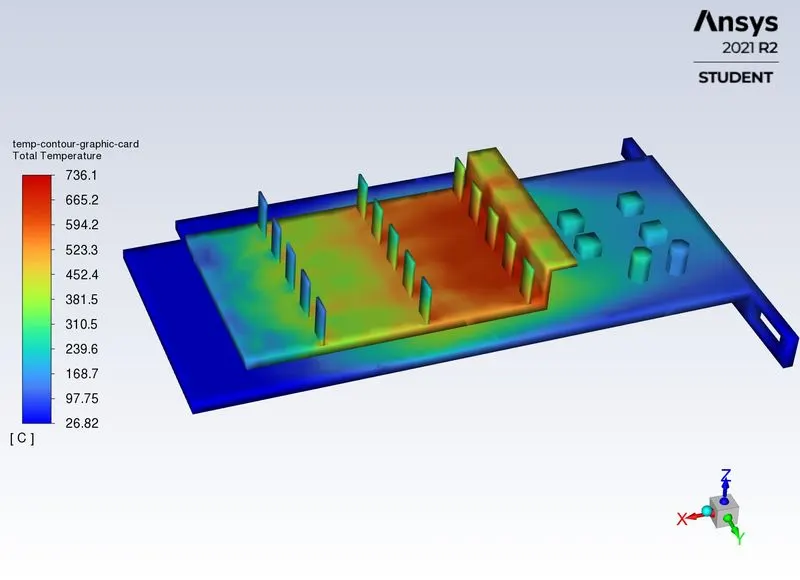
Temperature Contour
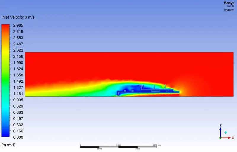
Velocity cut plane profile
Results for inlet velocity of 5 meter per second
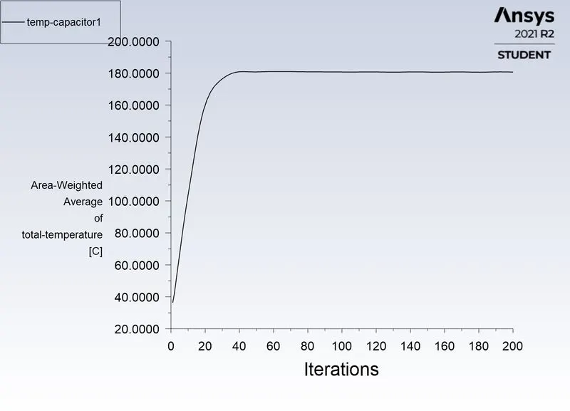
Capacitor 1 temperature
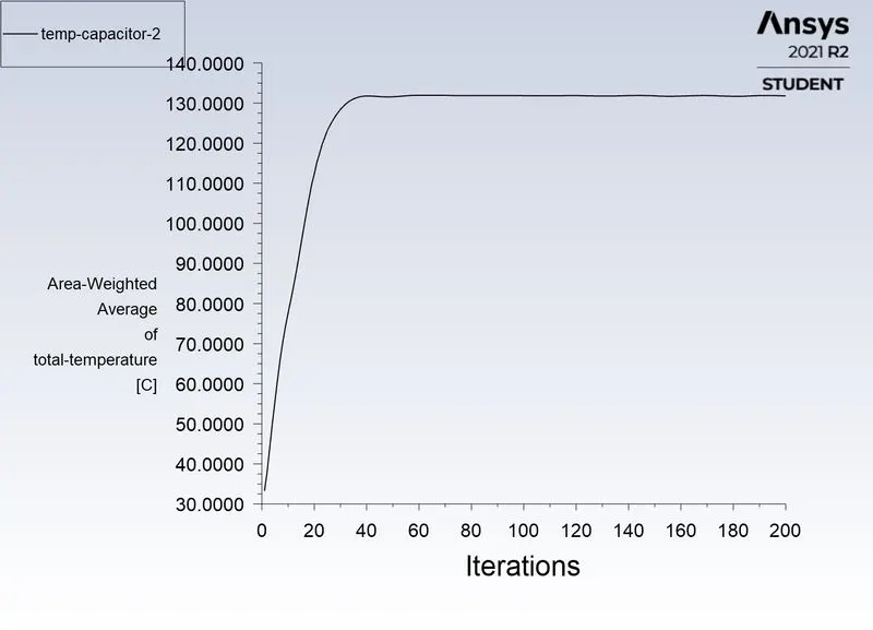
Capacitor 2 temperature
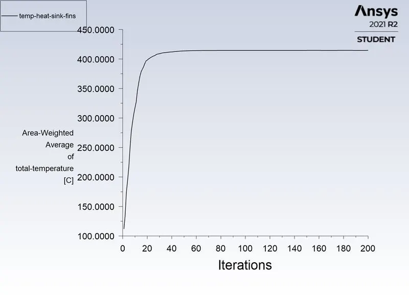
Heat sink fins temperature
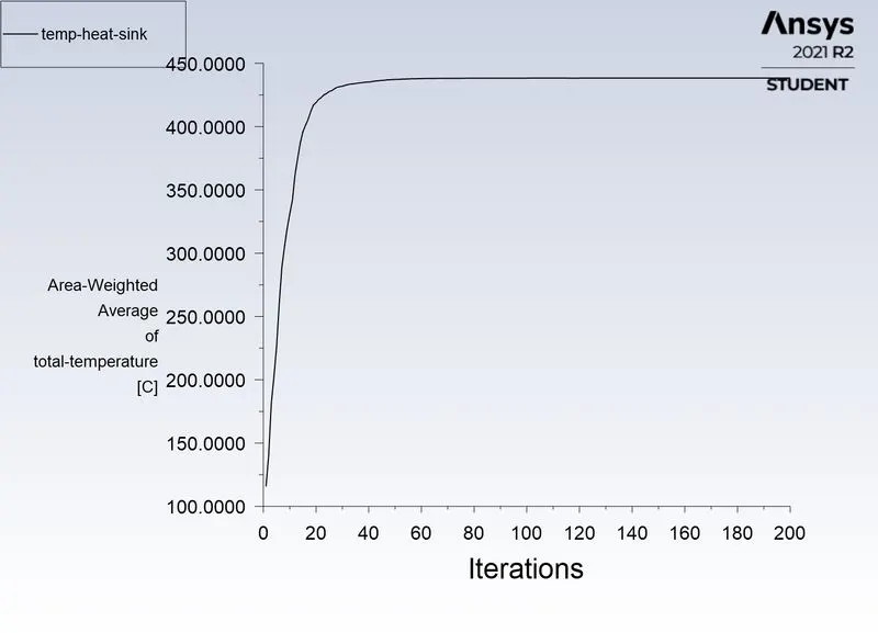
Heat sink temperature
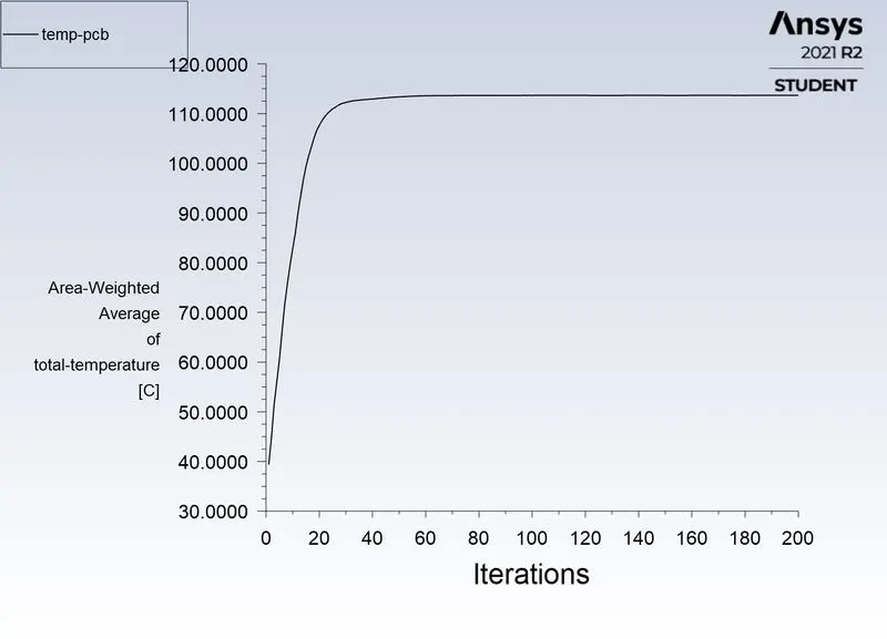
pcb temperature
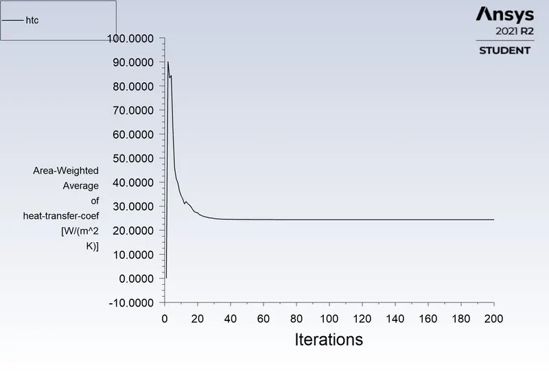
Convective Heat transfer coefficient
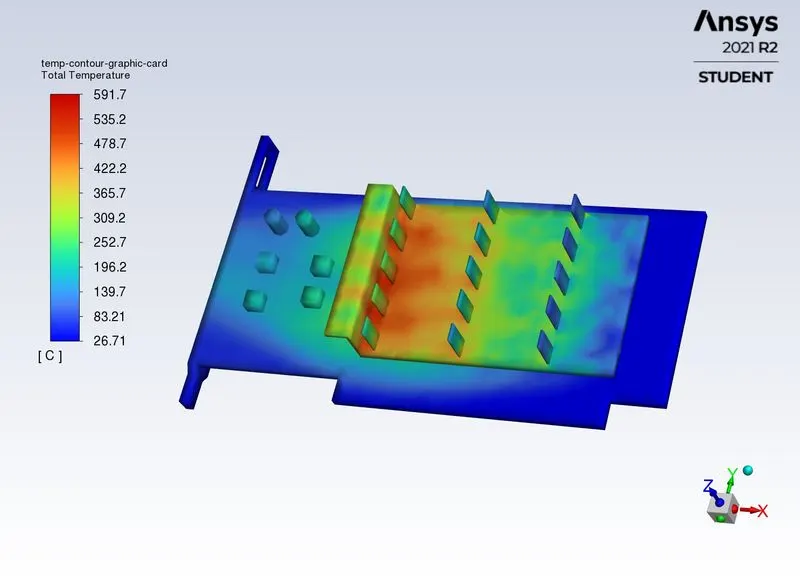
Temperature contour
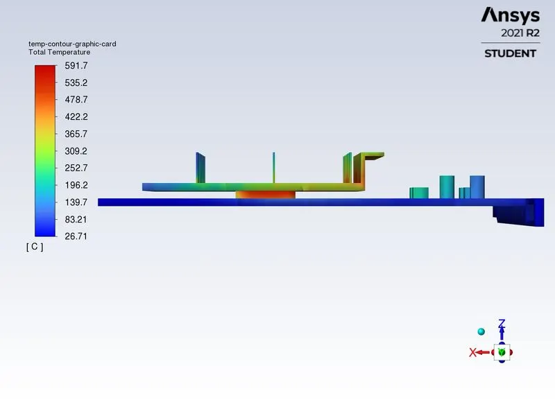
Temperature contour-2
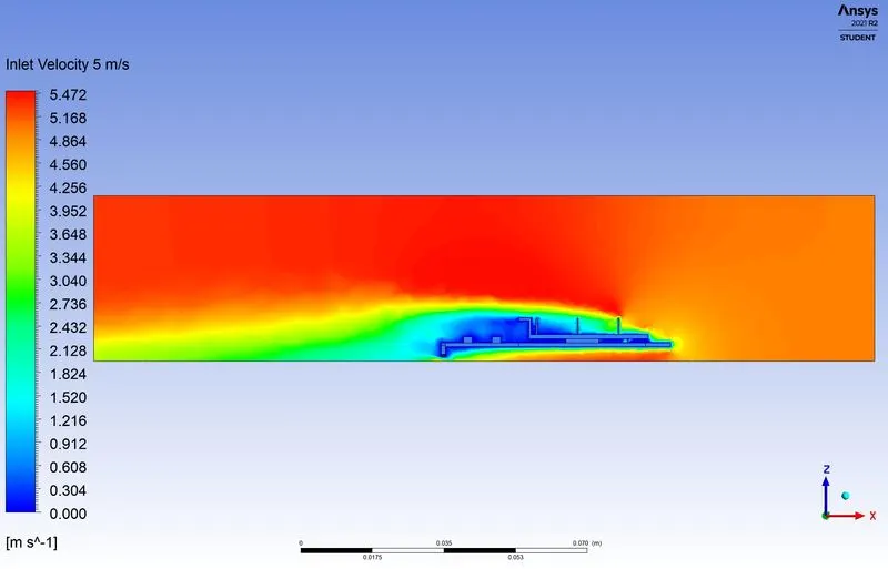
Velocity cut plane profile
Conclusions:
- The heat transfer coefficient keeps on increasing as the velocity increases. This shows better cooling for higher velocities.
- Peak temperature reached also reduces as velocity increases.
- Convection is the combination of conduction and advection. If the velocity of fluid increases, that increases the rate of advection, which increases convective htc.
- Convective htc for air at 1 meter per second = 7 watts per meter square kelvin
- Convective htc for air at 3 meter per second = 16.7 watts per meter square kelvin
- Convective htc for air at 5 meter per second = 24.4 watts per meter square kelvin
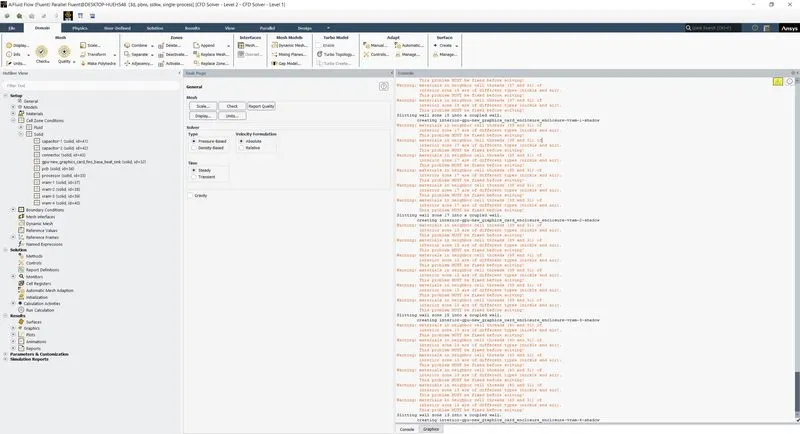
Warning errors in loading stage in fluent when Named selections do not have interface names given.
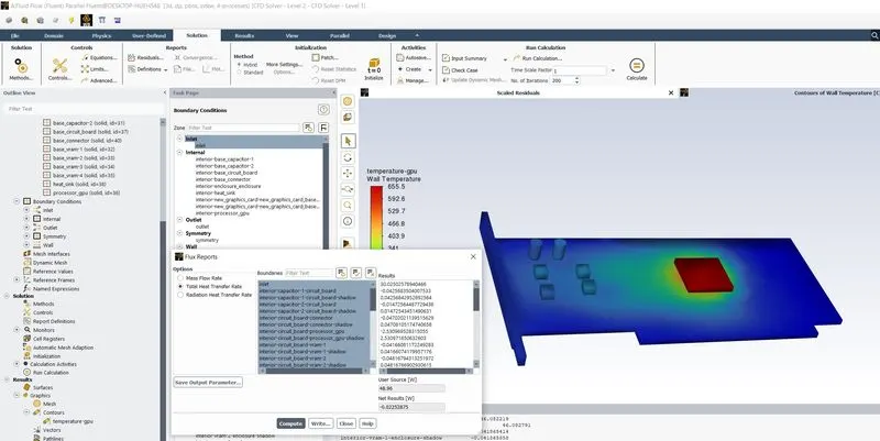
One way of convective heat transfer validation.
Smaller is the value of net results, which is obtained upon selecting all the boundaries and clicking on compute, better converged is the result.
Upon inspection, and from contours, hotspots ar formed on heat sink and processor interface and this can also be seen from temperature contours.
Convergence was checked using the fluxes for convective heat transfer coefficient, under reports tab, a snippet of the same is attached above.