Week 6 - CHT Analysis on a Graphics card
AIM: to simulate the conjugate heat transfer on the graphics card and show the results of wall haet transfer co efficient and the contoursa of the heat flow inside the enclosure(domain).
- given conditions are velocity inside the enclose is between the 1-5 m/s.
- have to give results for the 3 simulation with variying mesh sizes.
introduction to graphics card:
the graphics card mainly consists of the 3 parts
- FINS
- BASE OF THE GRAPHICS CARD.
- MAIN PROCESSSOR .
FINS: which are use to desipate the heat of the generated heat inside the cpu(graphics card).
BASE: is the component that consists of the many electonic components like the diode, transistors, etc
PROCESSOR: is is manily made up the silicon in which every calculaton every functions are mainly controlled by the graphics card.
why do we need the conjugate heat transfer analysis on the graphicscard
- we supply so much amount of power to the graphics card but only little amount of the power is converted into useful work.
- on the other hand the remaining power is converted into the heat energy. so nowadays we are doing the heat transfer analysis on the graphics card because we have to know how much of the energy converted into useful work and how much of the energy is converted into the heat.
- rather than that engineers are developing more efficient graphics cards os the conjugate heat transfer analysis on the graphics card is more important to study about its efficiency .
types of the materials use for the graphics card components:
- FINS: standard aluminium
density: 2719 `(kg)/m^3`
heat capacity: 871 `J/(Kg k)`
thermal conductivity: 150 `w/(mK`
- BASE: glass reinforced epoxy laminate material.
density: 1850 (kg)/m^3`
heat capacity: 950 `J/(Kg k)`
thermal conductivity: 0.29`w/(mK`
- PROCESSOR: silicon.
density: 2000`(kg)/m^3`
heat capacity: 710`J/(Kg k)`
thermal conductivity:150`w/(mK`
- FLUID MEDIUM: air.
density:1.220`(kg)/m^3`
heat capacity:1006.43`J/(Kg k)`
thermal conductivity: 0.024`w/(mk`
TO CALCULATE POWER PER UNIT VOLUME
The processor is sandwiched in between the base and the fins as shown above. The processor produces heat with its usage. The base is used to support the overall assembly. The fins conduct the heat produced by the processor and thereby cooling the processor. The fins are cooled by the application of air, the air at room temperature (25 C) passes over the graphic card assembly and the heat is carried away by it through convection. The fins provide extra surface area so as to increase the convection process.
VOLUME OF PROCESSSOR = `l*B*H`=`1mm*8mm**8mm`
power generation of the processor=`130 wats`
so power generated per unit volume =total power/total volume
i.e =`130/(1mm*8mm*8mm)`
i.e =2031250000`w/m^3`
MODELLING APPROACH:
there are five parts ;
- geometry
- mesh
- setup
- solution
- results
this is whole component
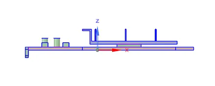
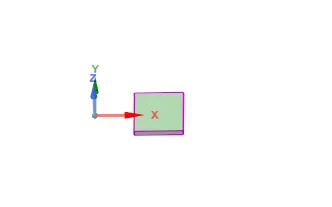
whole component processor
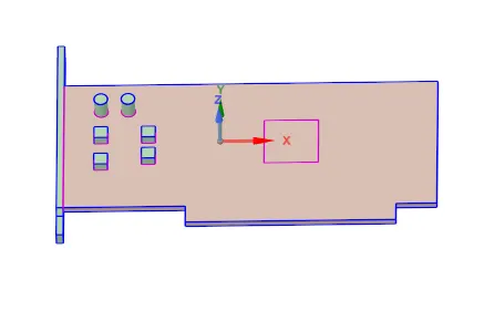
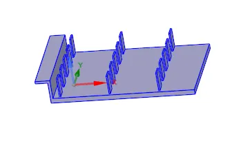
base fins
- in space claim we can create geometry and we can edit the given geometry.
- in this case we import the geometry from the data base.
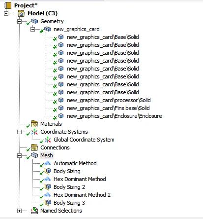
- and there are four different components assembled into a single assembly.
- then we enable share topology to share and eliminate the interferences in the geometry.
MESH:
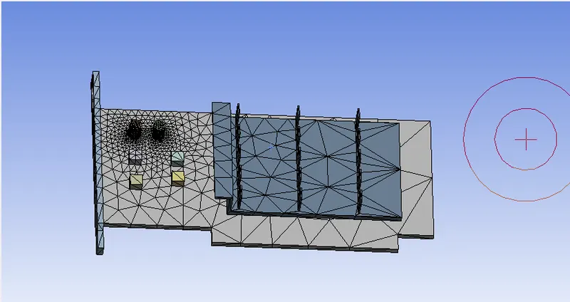
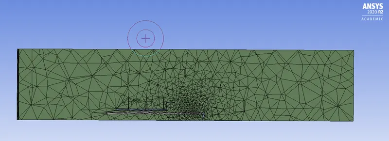
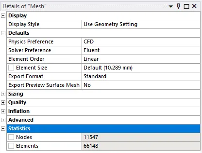
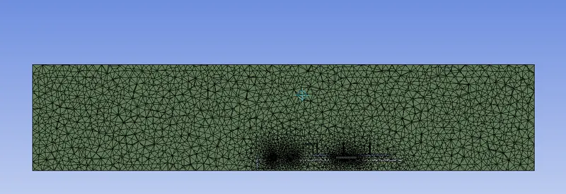
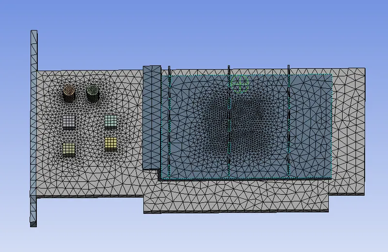
- this is the base line mesh that will be generated by the mesh itself.
- automated mesh is not refined so we cannot capture the results at the every point accurately .
- so we go through with the very refined mesh to capture the physics perfectly at every point.
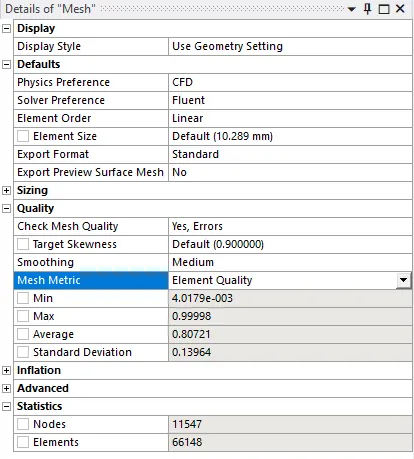
- these are the mesh settings where we can give the sizes of the elements to the meshing.
- we can select the max size and the minimum sizes.
- and we can check the quality of the elements of the mesh.
- we can use any kind of the mesh for the particular area.
- if we go to mesh martix we can check the quality of the mesh in that if we choose the element quality we can see.
SOLUTION: (solver requirements)
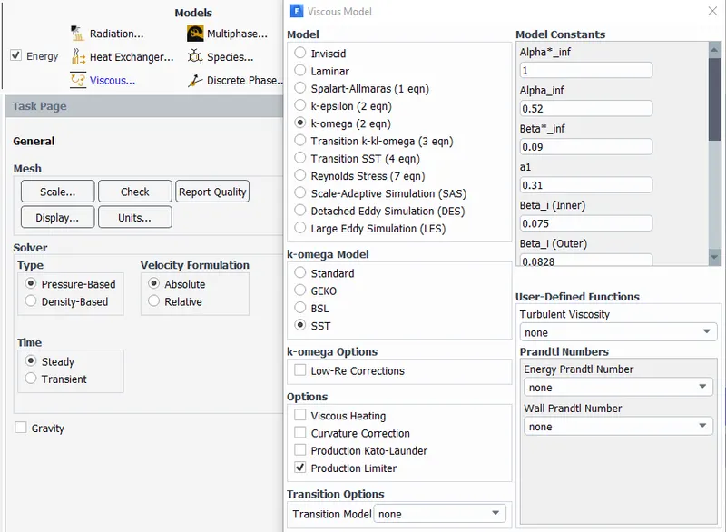
- we us the pressure-based solver for the soluton of this problem because the pressure based solver used in the low mach number flow the velocity of the flow is very less so we are using the pressure based solver.
- we are using the steady-state solution because we are only want to see the end results.
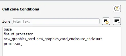
- after the solver is chosen we go for the boundary conditions and selection of the materiaso for every part we have to choose l.
- we gaven the name for every part all the parts are made up of the different material so we have to select the different materils for every part.
- for this method go to physics close cell boundaries choose material for different parts
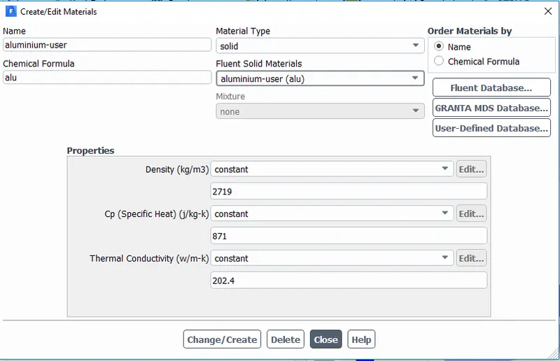
- if you want to create the user defined materials go to the fluent data base and hit on copy it copy fot the main settings.
- the you input your required properties and click on the change / create it will be generated and you can use that.
- then you can choose then which ever material you wnt for any part.

- then we use hybrid initialization and then we hit calculate and gave a number of iterations.
GRID INDEPENDENCE TEST:
CASE2:
CASE3:
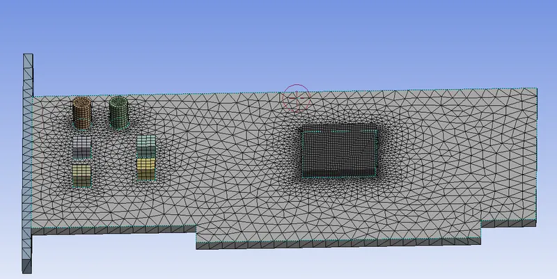
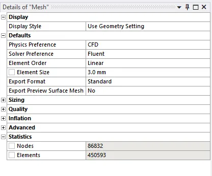
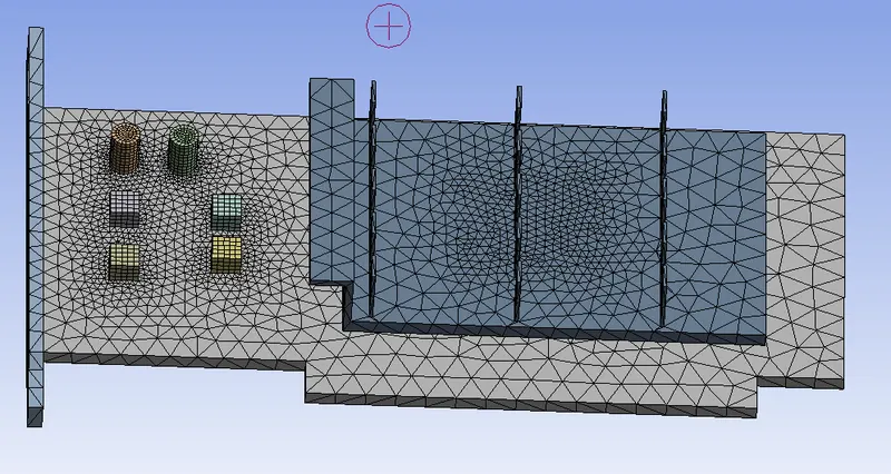
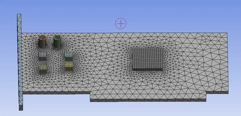
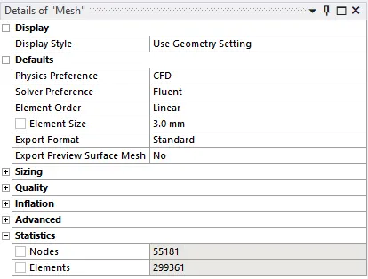
- for grid independence test we go through the different mesh sizes we choose the mesh with same results but have less compuatation time. so for the second case the mesh size was quite samll we are getting the same results for different mesh size.
- so we are slecting the case 2 because it requires less computation time.
- and we have to refine the regions where we want the more accurate results.
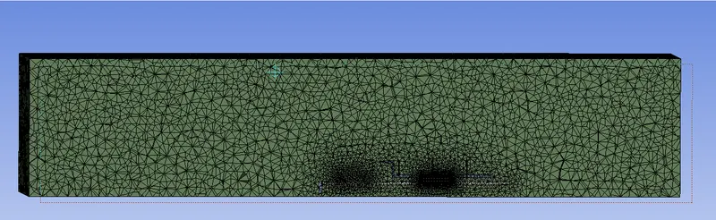
- we refined the area where the mesh is course like heat generation occurs at the processor we we refined taat area.
| CASES | CASE2 | CASE2 | CASE3 |
| no of elements | 66148 | 3mm | 3mm but other body sizing element size is changed |
| size of the elements | 10mm | 299361 | 450593 |
RESULTS:
FOR CASE 1 WITH BASE MESH AND INLET VELOCITY OD 2 m/s
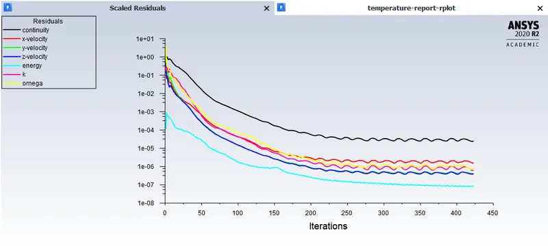
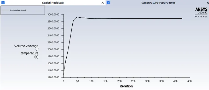
we can say the solution is converging because the change in residuals very small. as the residuals become so low it means that our error is very very small and we can say that our solution is converging.
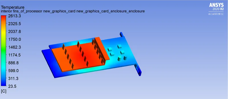
our base made up of the epoxy in which the thermal conductivity is very less so the base is having very low temperature and,the fins are made up of the alunimium so thermal conductivity is very high and is used to dissipate the heat out of the processor so it having the high temperature.
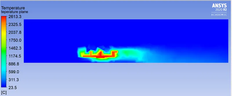
this is the side view of the processor the mesh is very course so the solution we are getting not accurate and the simulation which are showing in not pure relaible.
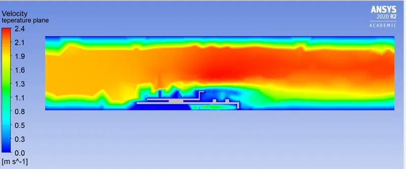
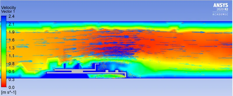
the velocity at the at the inlet is 2m/s but as the area decreases the velocity is very high because the as the area decreases velocity increases. so at the top of the processor velocity is more.
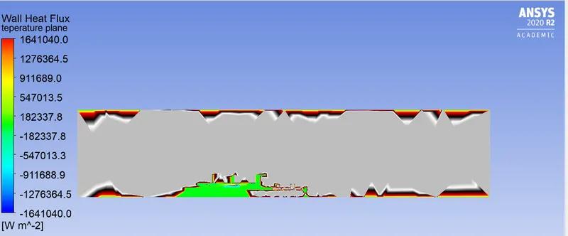
this graph is showing the wall heat flux the amount of heat is passing through the particular area (unit area)
RESULTS FOR CASE 2 WITH REFINED MESH AND INLET VELOCITY OF THE 2m/s
Case2: velocity 3m/s
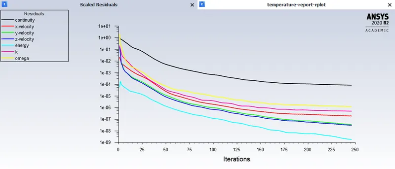
The K-epsilon realizable turbulence model used to solve this problem since the solution converges faster. The velocity at the inlet (the free-stream velocity) is 3m/s and the temperature 25 C. The heat generation term is added to the processor in the cell conditions tab. The solution was run for 250 iterations and from the trend of the plot, we can say that the solution converges after performing around 150 iterations.
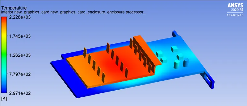
The highest temperature attained by the graphic card for this condition is 387.804K. From the temperature contour shown above, we can see that the temperature of the fins is comparatively higher than that to the base. This is simply because the copper material used for the fins has a greater thermal conductivity than that of steel which is used for the base. This is desirable since the main application of the fins is to dissipate the heat, and if the temperature of the fins is high, the more heat can be dissipated.
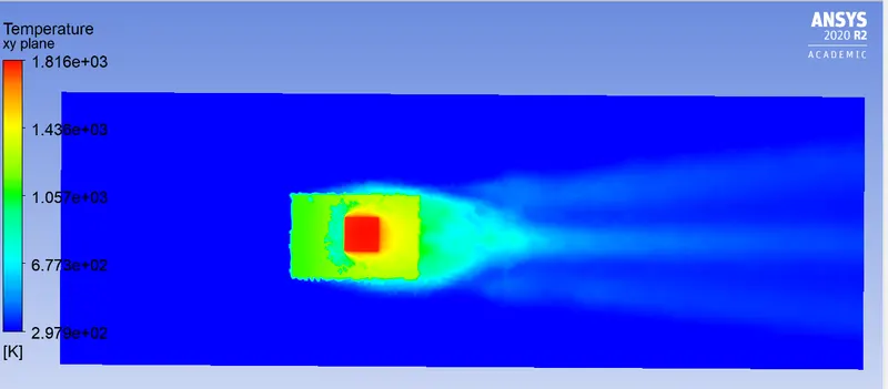
The potential hotspot in the graphic card is the processor and the region which is in direct contact with it since it is the only heat-generating part in the entire assembly. The temperature of the remaining components in the assembly is influenced by the heat generated by the processor. In turn, the processor produces a higher amount of heat as its workload increases. In this simulation, the heat generation is kept constant.
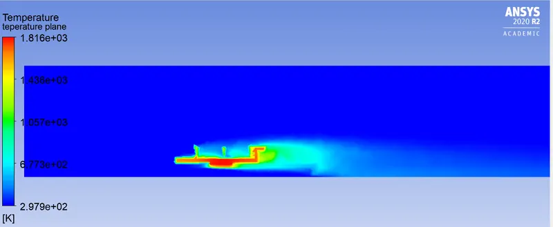
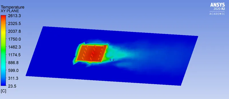
The above temperature contours are on the plane passing through the graphic card assembly. The temperature from the inlet fairly remains constant until it encounters the graphic card assembly. The temperature of air dramatically increases as it passes over the graphic card assembly due to the phenomenon of convection, wherein the heat is transferred from the solid to the fluid. This heat is carried away by air and the temperature at the fins is maintained.
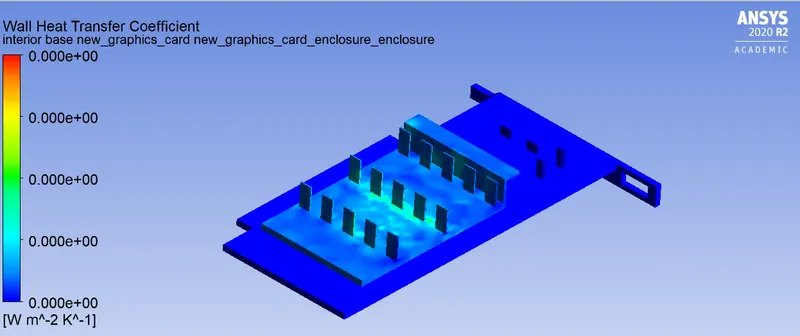
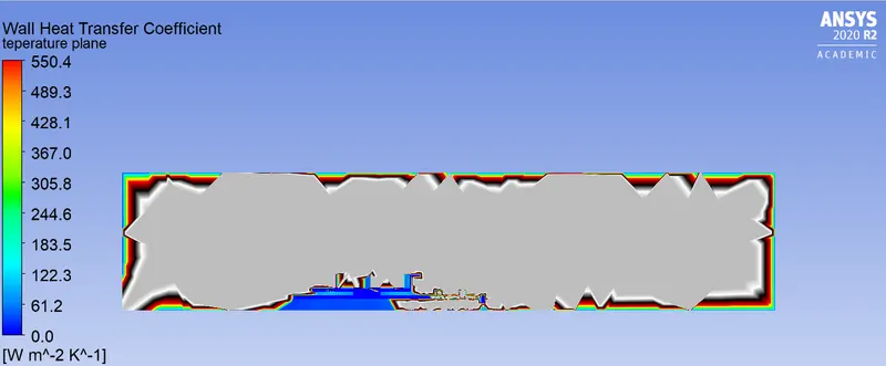
The highest wall heat transfer coefficient obtained
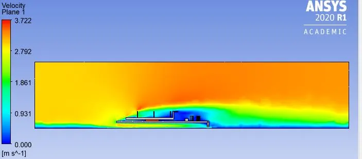
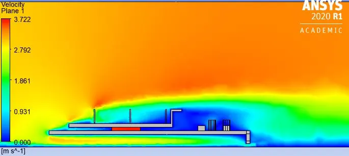
The above velocity contours are on the plane passing through the graphic card assembly. The three walls of the enclosure were given symmetry boundary condition, whereas the wall present below the base of the graphic card was given wall no-slip boundary condition. This is because the base of the graphic card is resting on a surface, which will have a similar boundary condition as we defined. Hence the velocity magnitude at the bottom of the wall is zero.
RESULTS FOR CASE 3 WITH REFINED MESH AND INLET VELOCITY OF THE 5m/s
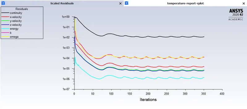
we can say the solution is converging because the change in residuals very small. as the residuals become so low it means that our error is very very small and we can say that our solution is coverging.
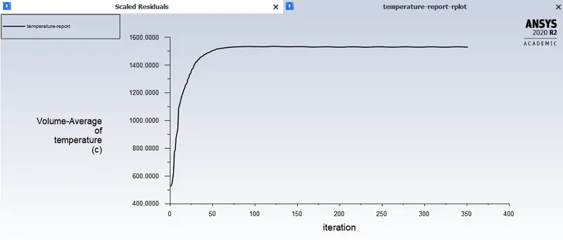
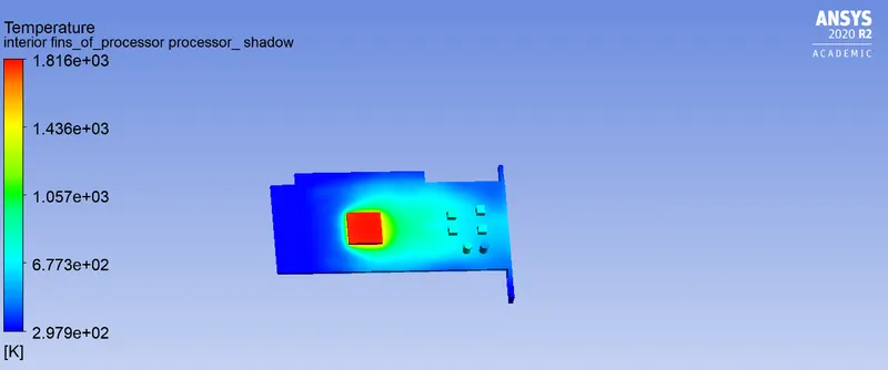
The above temperature contours are on the plane passing through the graphic card assembly. The temperature from the inlet fairly remains constant until it encounters the graphic card assembly. The temperature of air dramatically increases as it passes over the graphic card assembly due to the phenomenon of convection, wherein the heat is transferred from the solid to the fluid. This heat is carried away by air and the temperature at the fins is maintained.
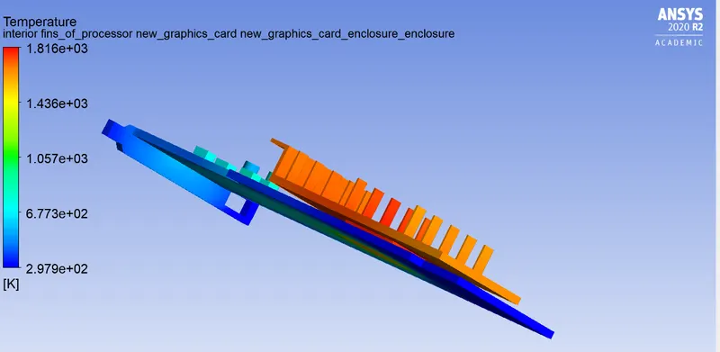
The temperature from the inlet fairly remains constant until it encounters the graphic card assembly. The temperature of air dramatically increases as it passes over the graphic card assembly due to the phenomenon of convection and decrease in the areaa of the flow, wherein the heat is transferred from the solid to the fluid. This heat is carried away by air and the temperature at the fins is become less because of the temperatureis taken away from the ait from the surface of the fins.
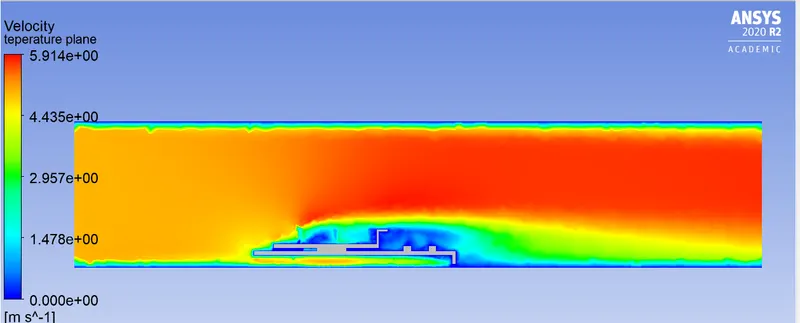
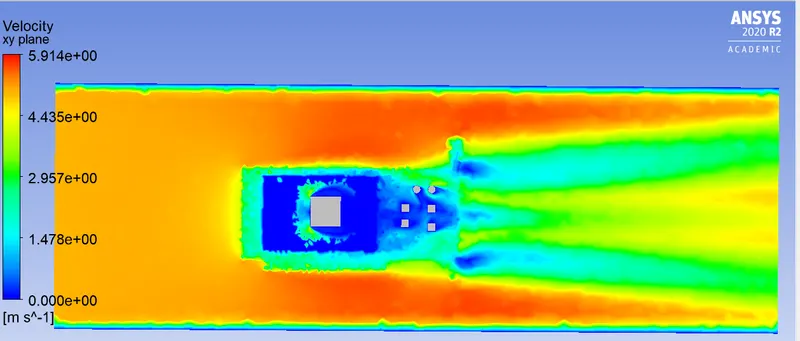
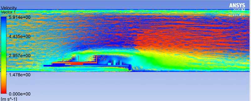
The above velocity contours are on the plane passing through the graphic card assembly. The three walls of the enclosure were given symmetry boundary condition, whereas the wall present below the base of the graphic card was given wall no-slip boundary condition. This is because the base of the graphic card is resting on a surface, which will have a similar boundary condition as we defined. Hence the velocity magnitude at the bottom of the wall is zero.
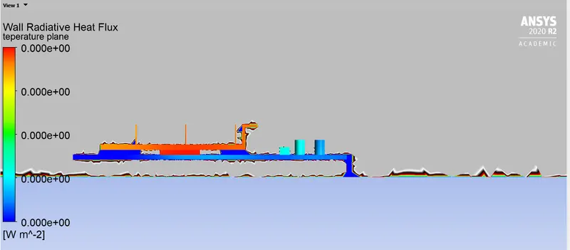
potential hotspot zone
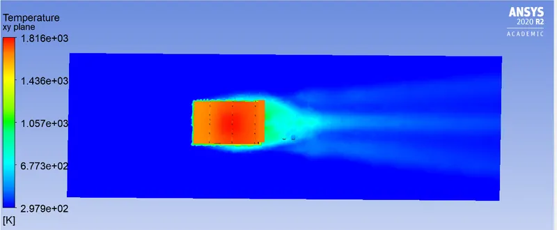
- this is called as the potential hotspot zone because the temperature arises from the center where the processor is held.
- processor is the reason of heat generation.
- hotspot means where the heat is generated as supplied throughout the domain.
##conclusion
- after doing this project we understand how to simulate the temperature variation along the graphics card.
- After successfully simulating the cooling of a working GPU, the following points were inferred from the results and observations;
- The maximum temperature attained by the gpu was lowest for the highest inlet velocity case. The greater velocity of air provided more mass transfer and hence greater cooling for the processor.
- The heat transfer coefficient was also the highest for the same case as the aluminium fins are taking away more heat from the processor than the rest of the cases as it is being cooled at a faster rate.
- The potential hot-spots were observed at the processor epoxy interface and fin-Processor interface as these parts are in direct contact with the heat source. The low conductivity of the epoxy material makes it a dominant hotspot.