Week 6 - CHT Analysis on a Graphics card
Aim:
- To perform a steady-state conjugate heat transfer analysis on a model of a graphics card.
- To run the simulation by varying the velocity from 1m/sec to 5m/sec for at least 3 velocities and discuss the results.
- To run the simulation for best possible mesh with combination of coarse and refined mesh in different regions.
- To explain the reason for choosing the particular mesh settings.
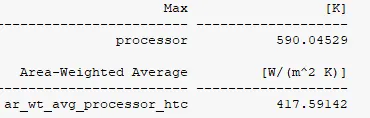
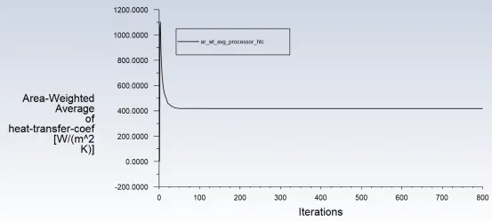
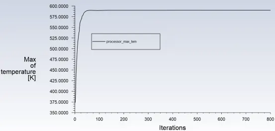
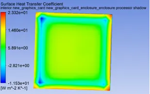
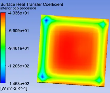
- To find out the maximum temperature and heat transfer coefficient attained by the processor.
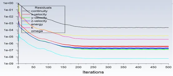
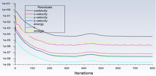
- To prove that the simulation has achieved convergence with appropriate images and plots.
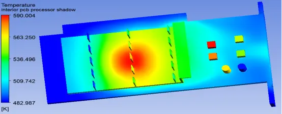
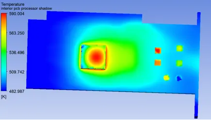
- To identify potential hotspots on the model.
Theory:
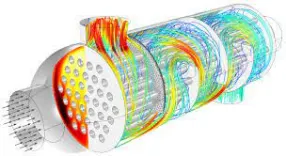
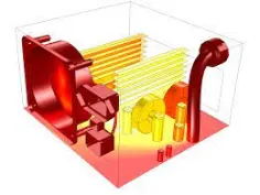
The Conjugate Heat Transfer (CHT) analysis type allows for the simulation of heat transfer between solid and fluid domains by exchanging thermal energy at the interfaces between them. computational fluid dynamics and more specifically conjugate heat transfer analysis can accurately predict heat transfer by simultaneous solving all the relevant solid and flow field heat transfer processes. Typical applications of this analysis type exist as, but are not limited to, the simulation of heatexchangers, cooling of electronic equipment, and general-purpose cooling and heating systems.
Inlet conditions:
In a CHT simulation, the computational domain will be solved for three fields: pressure (P) and velocity (U), and temperature (T). Here the pressure is referred to as Modified pressure and takes absolute values only. Additional turbulent transport quantities may be included based on the turbulence model selected. Under Initial conditions, these values can be initialized for the whole domain or a sub-domain for each region.
Boundary conditions:
Boundary conditions help to add a closure to the problem in hand by defining how a system interacts with the environment. This detailed list of available boundary conditions leads to dedicated pages each explaining their importance and how they can be applied to the domain boundaries.
Heat Transfer in a Solid
In most cases, heat transfer in solids, if only due to conduction, is described by Fourier’s law defining the conductive heat flux, q, proportional to the temperature gradient:

For a time-dependent problem, the temperature field in an immobile solid verifies the following form of the heat equation:

Heat Transfer in a Fluid
- Due to the fluid motion, three contributions to the heat equation are included:
- The transport of fluid implies energy transport too, which appears in the heat equation as the convective contribution. Depending on the thermal properties on the fluid and on the flow regime, either the convective or the conductive heat transfer can dominate.
- The viscous effects of the fluid flow produce fluid heating. This term is often neglected, nevertheless, its contribution is noticeable for fast flow in viscous fluids.
- As soon as a fluid density is temperature-dependent, a pressure work term contributes to the heat equation. This accounts for the well-known effect that, for example, compressing air produces heat.
Accounting for these contributions, in addition to conduction, results in the following transient heat equation for the temperature field in a fluid:

Applications:
Starting from simple examples in the 1960s, the conjugate heat transfer methods have become a more powerful tool for modeling and investigating nature phenomena and engineering systems in different areas ranging from aerospace and nuclear reactors to thermal goods treatment and food processing, from complex procedures in medicine to atmosphere/ocean thermal interaction in meteorology, and from relatively simple units to multistage, nonlinear processes.
Step by step procedure:
1. Space-claim:
- We need to export the geometry file from the respective folder.
- Now we need to share topology.
- Now we need to measure the area of solid.
- Do the dimensions check in order to take the measurements.
2. Mesh:
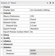
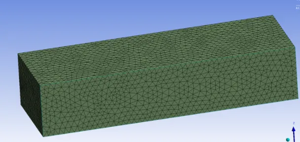
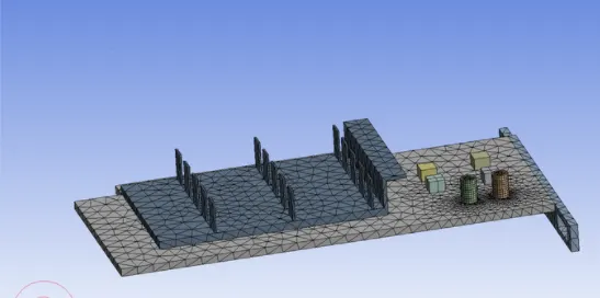
- First generate the baseline mesh.
- Clear the generated data and name the faces and body.
- Then we need to give body sizing for each components in graphic card or all to-gether
- Here I have done totally three simulations for grid independence study.
3. set-up:
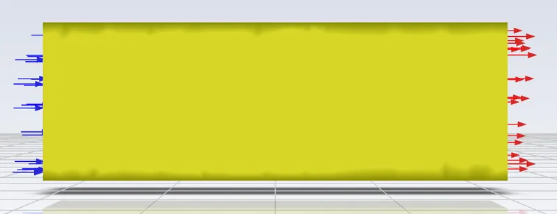
- Here we need to use pressure based, steady state solver and viscous model as k-omega SST.
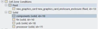
- Here I have divided graphic card into four parts; capacitors as components, base as PCB, fin and processor.
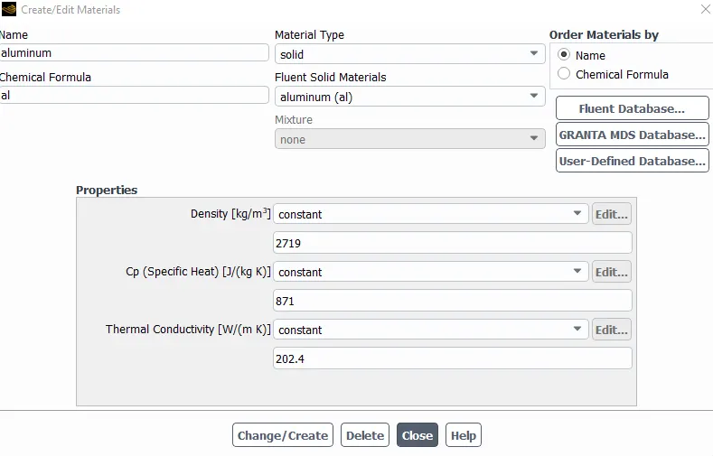
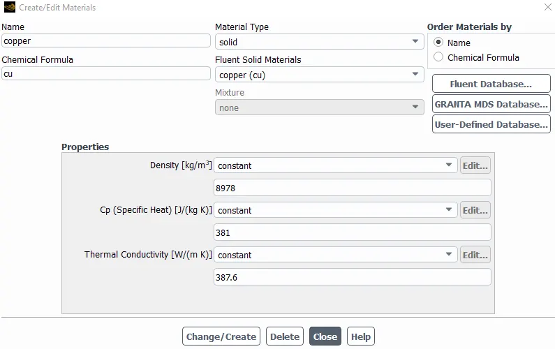
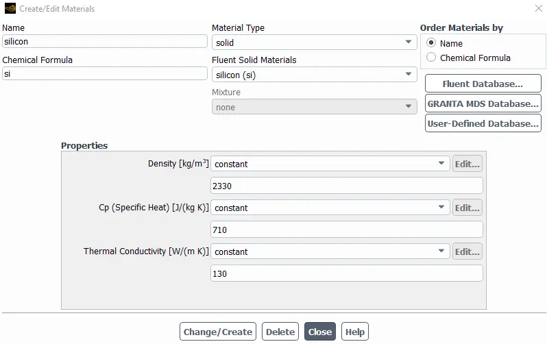
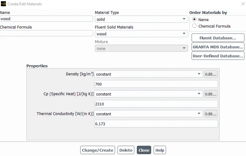
- The materials assigned as components-aluminium, PCB-wood, fin-copper and processor-silicon.
- Now we need to give the reference values, such as area, velocity, length and temperature.
- Initialize by hybrid.
Results:
Totally five simulation have done.
| Cases No | Mesh Element Count | velocity (m/s) |
| 1 | 82,565 | 1 |
| 2 | 2,22,354 | 1 |
| 3 | 4,75,583 | 1 |
| 4 | 4,75,583 | 3 |
| 5 | 4,75,583 | 5 |
case 1:
case 2:
case 3:
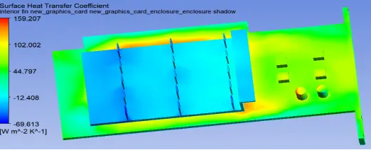
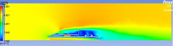
Here the contours are respect to solid and local
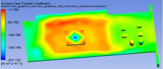
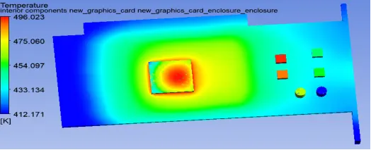
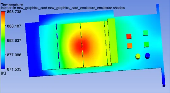
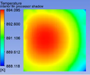
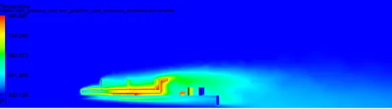
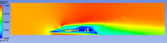
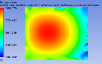
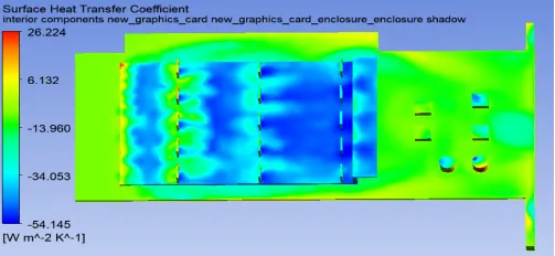
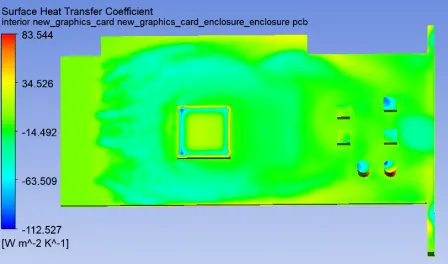
case 4:
Here the contours are respect to fluid and local
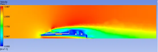
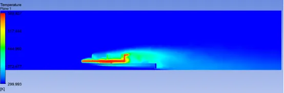
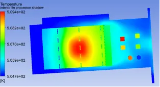
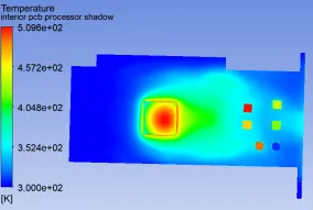
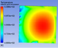
case 5:
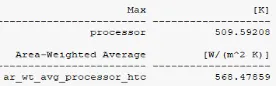
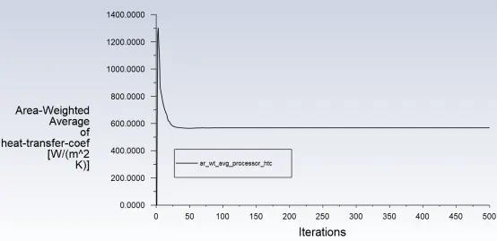
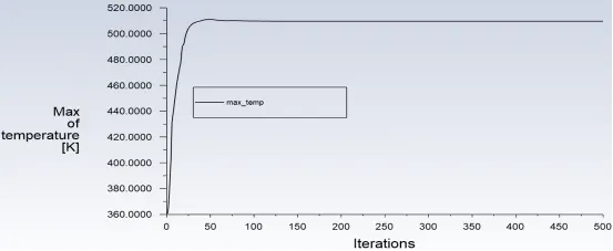
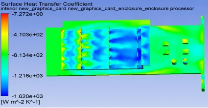
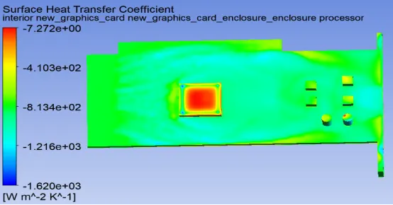
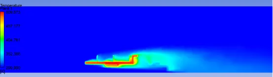
Here the contours are respect to fluid and local
Grid Independence Study:
| Cases No | Mesh Element Count | velocity (m/s) | Max Temperature of Processor (K) | Error percentage (%) |
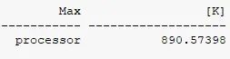
| 1 | 82,565 | 1 | 890.57398 | 0 |
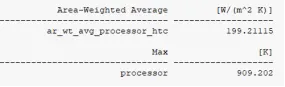
| 2 | 2,22,354 | 1 | 909.202 | 2 |
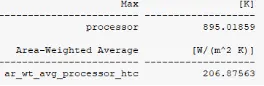
| 3 | 4,75,583 | 1 | 895.01859 | 0.49 |
Here we can say that grid independence study has good results because error percentage is less than 5 %
| Cases No | Mesh Element Count | velocity (m/s) | Max Temperature of Processor (K) |
| 4 | 4,75,583 | 3 | 590.04529 |
| 5 | 4,75,583 | 5 | 509.59208 |
Inference:
- The refined mesh is used for other two simulations case 4 and case 5 because from the grid independence study we cannot make any confirmation about the right output value, so the refined case is used since it took less iterations to converge and also the error percentage is less.
- In these simulations, I have observed a important point, that is when the velocity increases heat dissipation also increases, so the maximum temperature of processor decreases with increases in velocity.
- In all my cases more heat is dissipated to PCB board than fin, and I have found that is due to material selection, if I change the material according to the purpose so that this could be changed.
- From this experience, I can say that if more heat is dissipated from the source to fins and atmosphere, the graphic card will have extra life time and it will not affect the performance.
- Selection of right materials is very important because lots of heat is generated in the processor and this is not good for us to have and this has to be dissipated immediately, for this, we need to choose the material which has high thermal conductivity, so that it can take more heat when it has a physical contact which is called conduction.
- The hotspots are observed from the temperature contours and they are at center part of processor and at the contact of processor on the fin and this can be observed in the contour on the surface of fin from the top view.