Week 6 - CHT Analysis on a Graphics card
A conjugate heat transfer (CHT) corresponds with the combination of heat transfer in solids & heat transfer in fluids. In solids conduction dominates whereas in fluids convection dominates. In applications where working temperature is high, it is essential to calculated temperature distribution in solid to ensure it does not cross the metallurgical limit. Hence, it is necessary to solve the energy equation of the solid along with the fluid flow equations.
Heat transfer in a solid
In most cases, heat transfer in solids is only due to conduction, which is described by the Fourier’s law defining the conductive heat flux, q, proportional to the temperature gradient;
`q = -k*nablaT`
Heat transfer in a fluid
Due to fluid motion, three contributions to the heat equation are included:
- Transport of fluid involves energy transport too, which appears in the heat equation as the convective contribution.
- The viscous effects of fluid flow produce heating.
- If a fluid’s density is temperature-dependent, a pressure work term contributes to the heat equation.
The convective heat transfer is described by Newton's law of cooling which states that the rate of heat transfer from a body is proportional to the temperature difference between the body and the environment.
`Q = h*A*(T-T_infty)`
h is the heat transfer coefficient which depends on the flow behaviour, fluid properties.
A is the area of the body which is in contact with the fluid.
T is the temperature of the solid
Tinfinity is the free stream temperature
Conjugate heat transfer applications
Efficiently combining heat transfer in fluids and solids is the key to design coolers, heaters or heat exchangers. Fluids act as energy carriers on large distances. Forced convection is the most common way to achieve high heat transfer rate.
In heat exchangers solids are needed to separate fluids so that fluids exchange energy without mixing.
Heat sinks are usually made of metal with high thermal conductivity (e.g. copper or aluminium). They dissipate heat by increasing the exchange area between the solid and the surrounding fluid.
Graphic cards are now an essential part of modern computers. These improve the quality of the image that is displayed on a monitor. The graphics processing unit of GPU is the main component that performs computations. A discrete graphic card has its own random access memory, cooling system and other components designed specifically for processing video images.
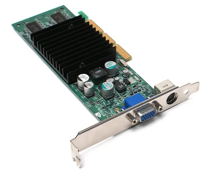
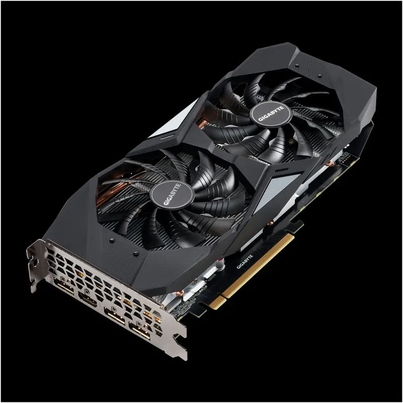
Modern GPUs with fins which spawn the entire length of the graphic card
With increasing processing power, the electrical power requirement of graphic cards has grown. Current graphic cards consume large amounts of power. Some GPUs have power consumption larger than any individual part in the computer. For e.g. the thermal design power of GeForce Titan RTX is 280 W. The thermal design power (TDP) is the maximum amount of heat generated in a computer chip that the cooling system in a computer is designed to dissipate. This is the power a cooling system dissipates without exceeding the junction temperature for the chip. The cooling is achieved by an active cooling method (conduction coupled with forced convection) such as a heat sink with a fan.
The figure above shows a graphic card with various components and a large heat sink or fins (coloured in black). These fins act as a heat sink which increases the effective surface area between the solid and the surrounding fluid. These are made of high thermal conductivity metals such as copper, aluminium. This is a relatively old graphic card as most modern graphic cards come with cooling fan/fans.
These graphic cards consume power ranging from 20-100 W. Most of this power is dissipated as heat which can be 99.9% of the total power. A power rating of 20 W is considered for this project.
OBJECTIVES
The objectives for this project are,
- To setup a steady-state simulation of conjugate heat transfer for a model of a graphics card.
- Create a body-fitted/conformal mesh to facilitate transfer of information between components.
- Determine the maximum temperature & heat transfer coefficient attained by the processor.
- Observe the effects of fluid velocity by varying the velocity between 1 m/s & 5 m/s.
- Identify potential hotspots on the model.
SOLVING & MODELLING APPROACH
- The domain is essentially divided into two domains fluid & solid domain. In fluid domain, the three dimensional continuity, momentum & energy equations are solved for pressure, velocity, temperature etc.
- In solid domain, diffusion is the only transport process and only the energy equation is solved for temperature.
- The fluid & solid energy equations are coupled for identical conditions at the solid-fluid interface such as the temperature & heat-flux.
- The inlet is velocity inlet whereas the outlet is a pressure outlet.
- For this case, the processor acts as a heat source & the fins as heat sink.
- The fluid domain has air as the material whereas for the graphic card different materials are defined for the processor, fins & base.
GEOMETRY
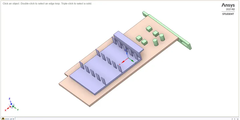
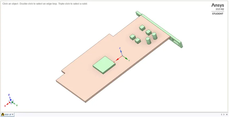
Graphic card Processor & base
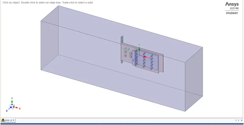
Fluid domain/enclosure around graphic card
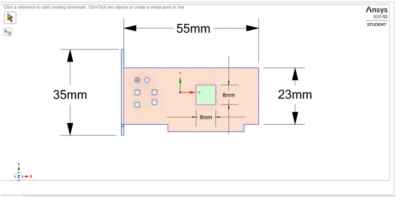
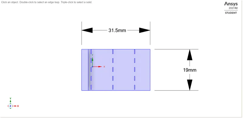
Dimensions for the components are (in mm)
Base = 55x23x1
Processor = 8x8x1
Fin base = 31.5x19x1
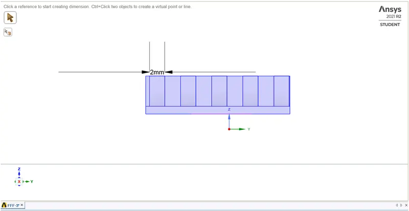
Fin = 4x2x0.25, a total of 15 fins.

MESH
A conformal mesh is created by enabling ‘Share’ topology in SpaceClaim. This helps to create a mesh that transits smoothly from one component to other without overlapping.
The mesh settings are,
Global
1. Element size = 4 mm
Number of elements = 281,255
2. Fins base
Body sizing
Size = 1mm
Capture curvature = no
3. Processor & Base
Body sizing
Size = 1mm
Capture curvature = no
4. Fluid domains
Size = 3 mm
Element quality
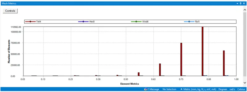
Average element quality is 0.82 with a standard deviation of 0.102777.
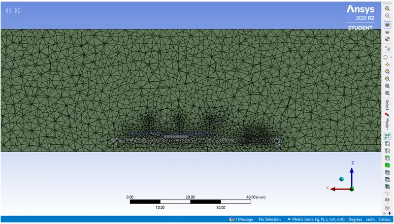
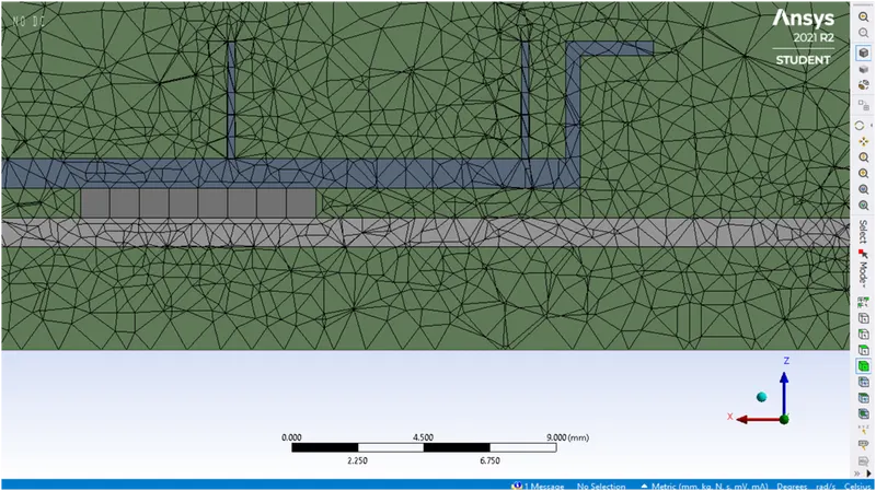
Close-up view shows a conformal mesh.
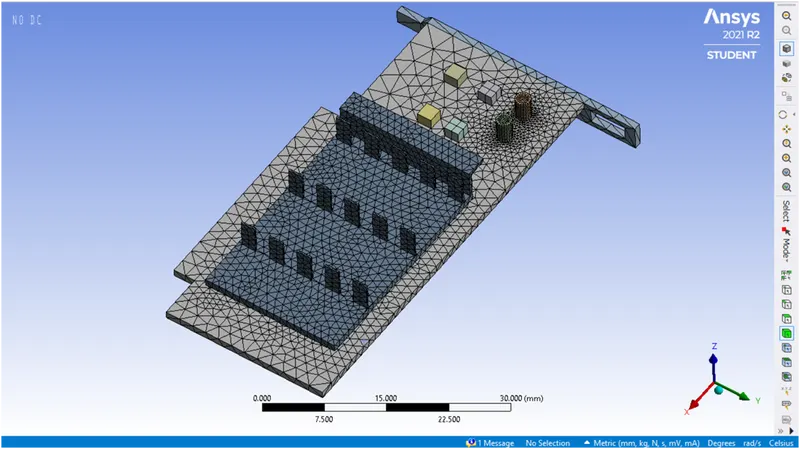
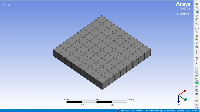
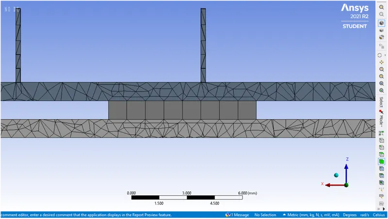
- The processor is a heat source which has a certain amount of heat dissipating per unit volume. The processor is coupled to fins & base through which heat is conducted.
- In order to faciliate this information transfer accurately the mesh need to be fine and conformal.
- This is done by applying body sizing to have independent control over the mesh.
SOLVER REQUIREMENTS
The computation of a velocity field requires computation of pressure field. This is done by a guessed pressure field which is used to solve the momentum equation. Various algorithms are implemented to do this such as SIMPLE, PISO etc. In Ansys Fluent, the ‘Coupled’ scheme is implemented for this case. A second-order upwind scheme is implemented for both momentum & energy equations.
The k-epsilon realizable turbulence model with scalable wall function is chosen.
The boundary conditions for the solver are
Inlet: - velocity ranging from 1-5 m/s
Outlet: - pressure (gauge) = 0 Pa
The interfaces within the solid are coupled whereas the interfaces between the solid & fluid are no-slip walls as well as coupled.
The materials choosen for the model are,
| Component | Material | Density kg/m^3 |
Thermal conductivity W/(m-K) |
Specific heat J/(kg-K) |
| Processor | Silicon | 2320 | 148 | 710 |
| Fins | Aluminium | 2719 | 202.4 | 871 |
| Base | FR4 (composite material for PCB) | 1850 | 0.81 | 1150 |
| Enclosure | Air | 1.225 | 0.0242 | 1006.43 |
While Aluminium is available in Fluent database, Silicon & FR4 had to defined as they are not available in Fluent.
RESULTS
For this project the simulation is performed for three inlet velocities between 1 to 5 m/s. The maximum temperature & heat transfer coefficient attained by the processor are determined. The iterations are performed until convergence is reached & potential hotspots on the model are identified.
The heat dissipation per unit volume from the processor is determined as follows,
We consider power dissipation for an average 20x20x2 mm processor. Q = 20/(0.02*0.02*0.002) = 25,000,000 W/m^3.
Case-1] Velocity of 2.4 m/s & 3.6 m/s
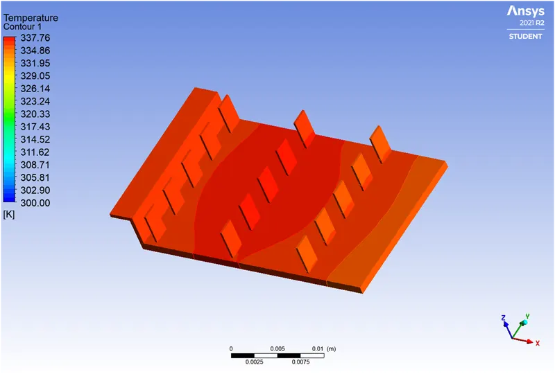
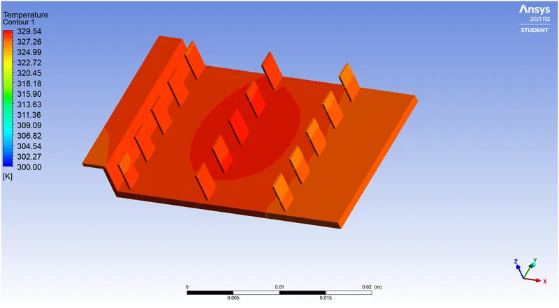
Temperature Contour for the model
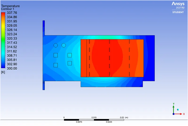
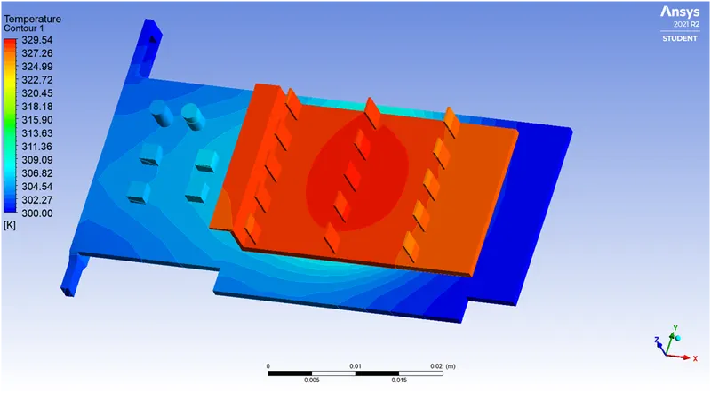
For fins
Processor& base
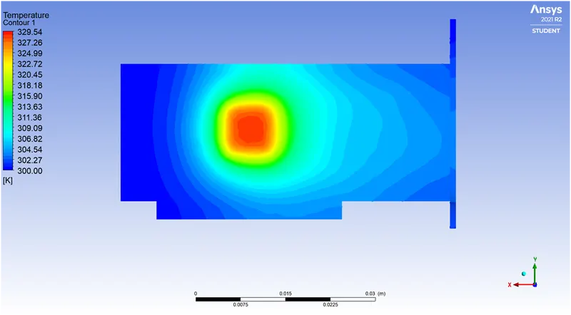
Processor
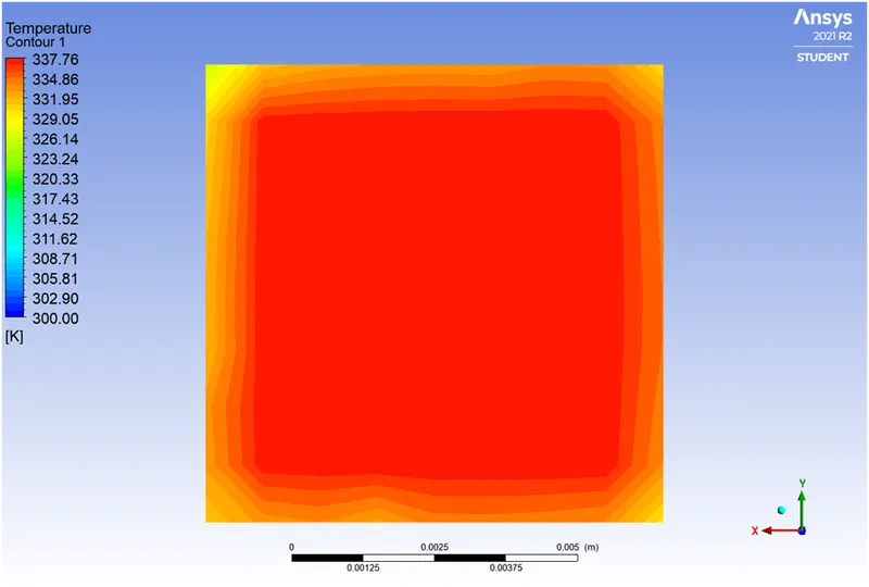
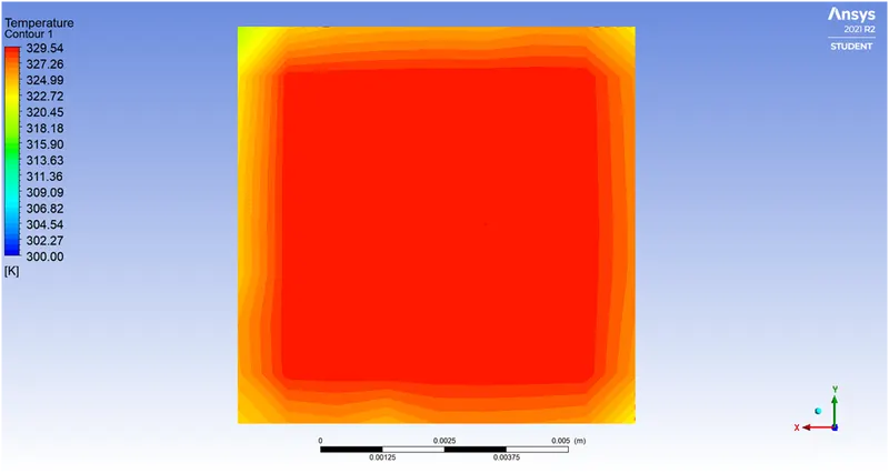
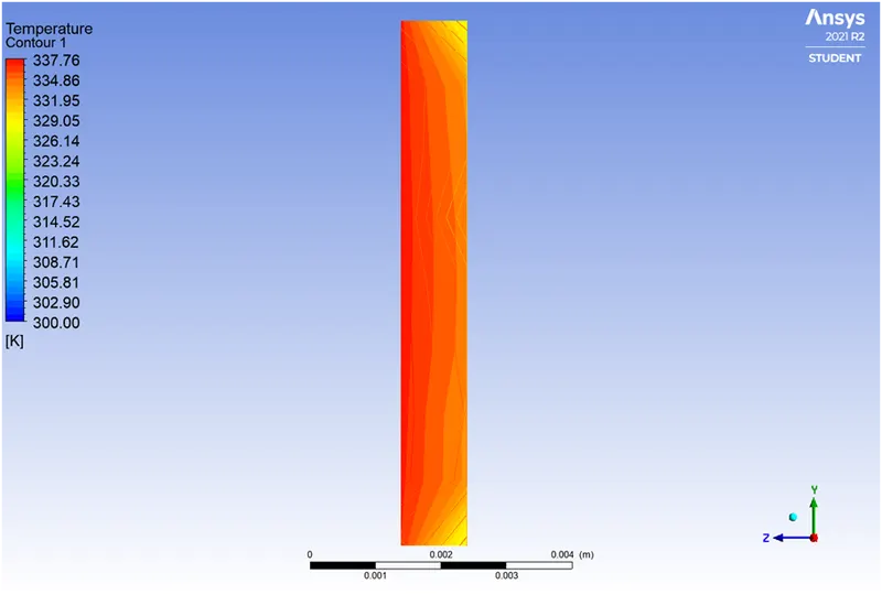
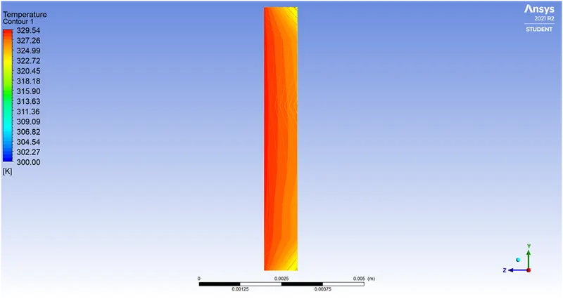
Processor side-view
Processor wall heat transfer coefficient
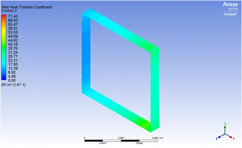
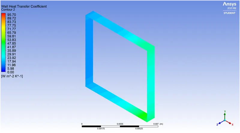
Fins -wall heat transfer coefficient
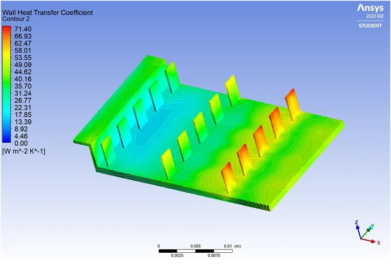
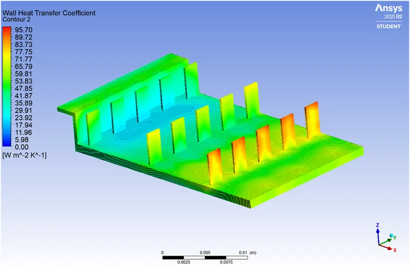
Results
| Velocity (m/s) | 2.4 | 3.6 |
| Processor maximum temperature | 337.76 | 329.54 |
|
Processor wall heat transfer coefficient W/(m^2 K) |
40.16 | 53.83 |
|
Fins maximum heat transfer coefficient W/(m^2 K) |
71.40 | 95.7 |
STREAMLINES & VECTOR PLOTS
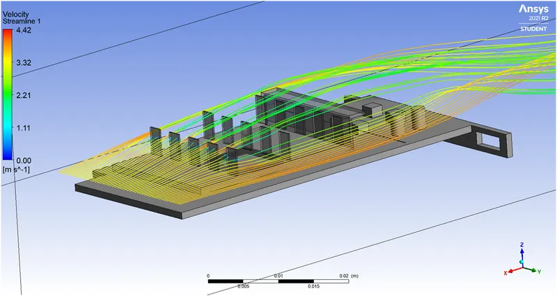
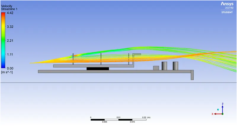
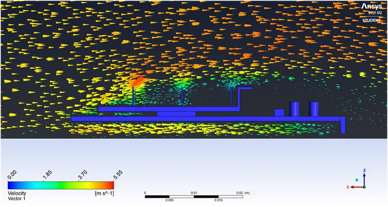
- It is visible from the streamlines & the vector plots that the fluid flow is deflected upwards due to the fins in the first row.
- This results into less flow rate into the subsequent rows of fins.
- The geometry of the fins base has a plate at the back which also deflects the flow. Due to this there is minimal flow in the rear part of the model and hence the cooling of those parts is affected as well.
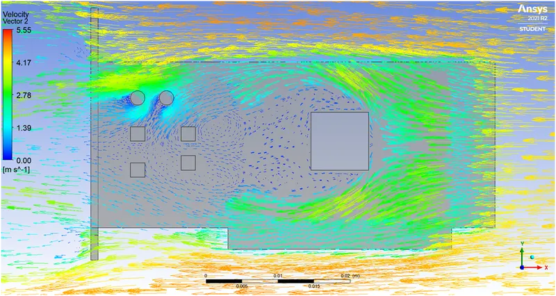
- The gap between the fins and the processor is very small, which results in a less flow rate in that portion. The streamlines for this are shown below.
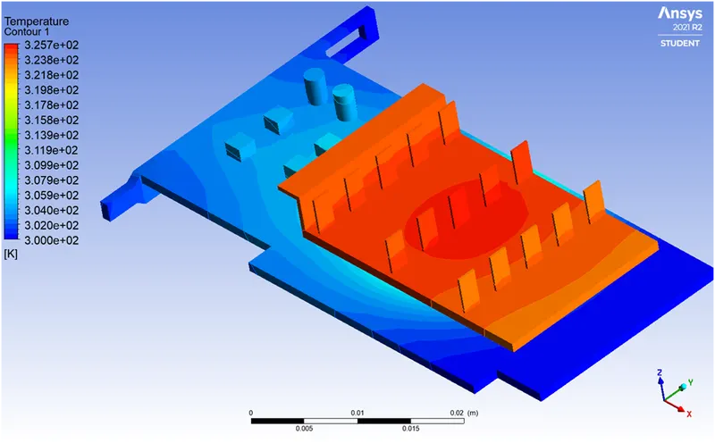
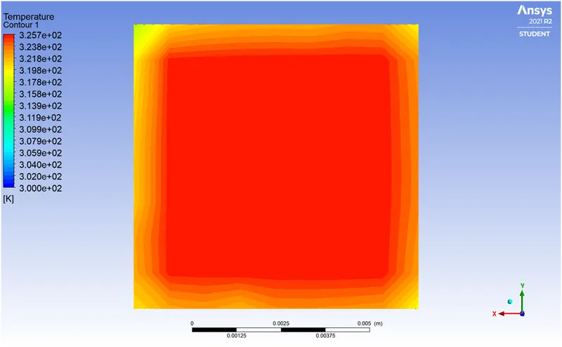
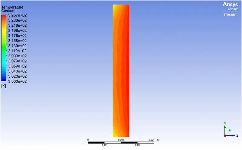
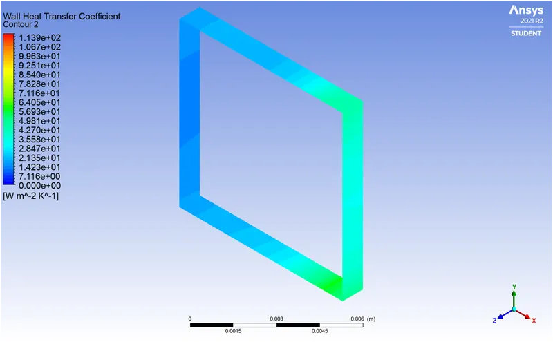
Case-3] 4.5 m/s
Temperature contour for model & base
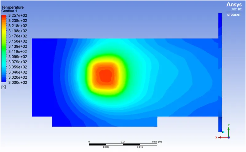
Processor front & side
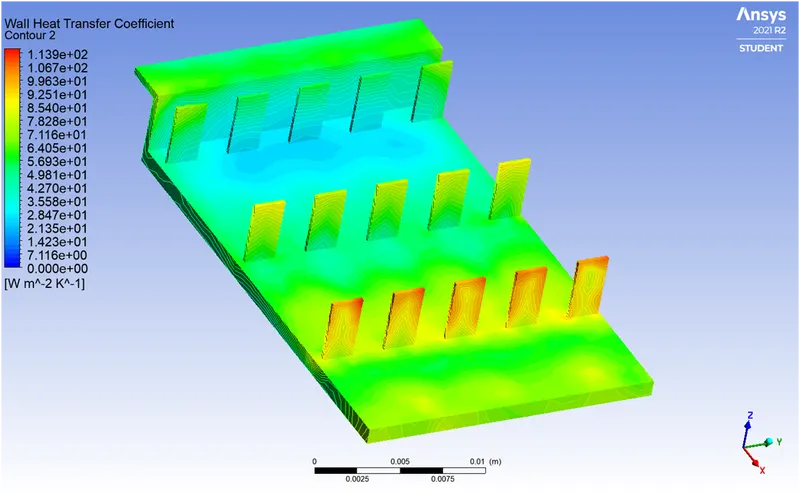
HTC for processor & fins
RESULTS
| Velocity (m/s) | 2.4 | 3.6 | 4.5 |
| Processor maximum temperature | 337.76 | 329.54 | 325.702 |
|
Processor wall heat transfer coefficient W/(m^2 K) |
40.16 | 53.83 | 64.05 |
|
Fins maximum heat transfer coefficient W/(m^2 K) |
71.40 | 95.7 | 113.9 |
Maximum temperature attained by the processor: - 337.76 K or 64.61 °C.
Maximum heat transfer coefficient attained by the processor: - 64.05 W/(m^2 K).
INFERENCES
- As the velocity is increased, the processor heat transfer coefficient increases.
- The Nusselt number is a dimensionless number which represents the enhancement of heat transfer through a fluid layer as a result of convection.
- The Nusselt number is related to the Reynolds & Prandtl number by the correlation.
- `Nu = 0.664*Re^0.5*Pr^0.33`
- As Re increases the Nusselt number increases.
- The htc is given by h = Nu*k/l. The htc is proportional to Nu.
- Hence the htc increases as well.
- The fins have a higher htc as compared to the processor which proves the importance of fins in cooling.
- The better configuration for the fins would be having them oriented as shown.
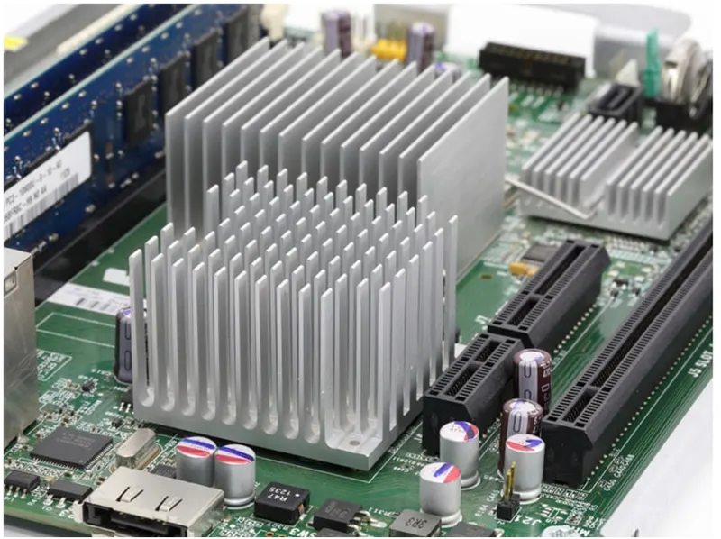
- This not only allows flow rate through but also increases the effective area for heat transfer as both the opposite areas of a fin are available for contact with fluid flow.