Week 6 - CHT Analysis on a Graphics card
Aim :
To perform a steady-state conjugate heat transfer analysis on a model of a graphics card in ansys fluent.
Objective :
- To run the simulation by varying the velocity from 1m/sec to 5m/sec for at least 3 velocities and discuss the results.
- To find out the maximum temperature and heat transfer coefficient attained by the processor.
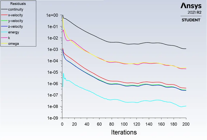
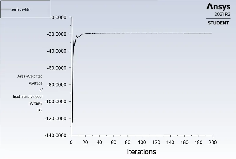
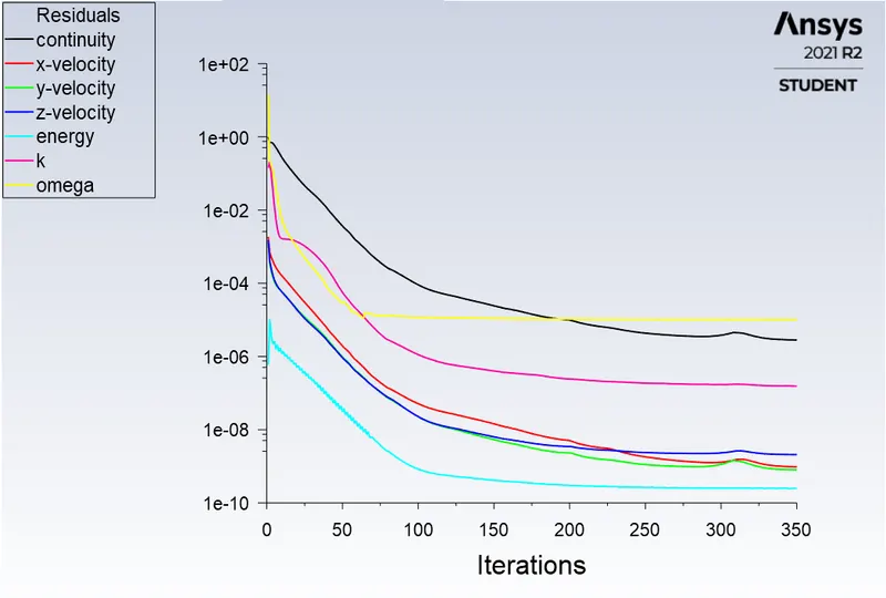
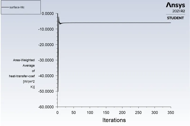
- To prove that the simulation has achieved convergence with appropriate images and plots.
- To identify potential hotspots on the model.
Conjugate Heat Transfer (CHT) :
- Thermal interaction between the fluid and the solid region it can be either natural convection or forced convection.
- In solid region we are simulating the heat conduction. The heat conduction is basically the diffusion of heat due to direct contact.
- In fluid regions we are dealing with the convection of heat. This is the kind of transfer of thermal energy due to the movement of fluid elements.
- At the interfaces between this two region there will be a thermal coupling. Because we are considering the transfer of mass and thermal energy at the same time both in solid and fluid and also we can consider the other methods of heat transfer which is radiation.
- In CHT analysis, thermal radiation also accounts for a equal share as engineering problems does not limit to conduction and convection.
- The principle of conduction is governed by Fourier's law of heat conduction, whereas convection is influenced by Newton's law of cooling.
- In engineering applications, heat transfer problems are complex to solve due to such combination of modes of heat transfer.
- These problems are tedious to solve through conventional (analytical) means and therefore creates a need for a numerical model which can approximate the physical process.
- CHT analysis is beneficial in accurately predicting solid temperature and heat transfer capabilties in engineering devices.
- Thermal engineers in industries are responsible for controlling heat transfer capabilities for their product to ensure efficient working as per standards.
Advantages of conjugate heat transfer :
- Understanding of the complex heat transfer mechanisms and the interactions between those mechanisms .
- To improve the performance of component and increase the lifespan of the components to be analyzed
- Conjugate Heat Transfer analysis provides the temperature distribution in solids and fluids, and clear insight on velocity distribution and mechanism of heat transfer of fluid, like in engines.
- It is more accurate and fast to simulate the problem.
- Can be used in complex scenarios like in automotive components or in power plant components.
- Multiple numbers of regions can be simulated.
- All types of region combinations can be simulated like solid-fluid,fluid-fluid, etc.
Applications of CHT :
Cooling of electronic devices, Heat exchangers, HVAC (Heating Ventilation and Air Conditioning), Air-cooled and liquid-cooled engines, turbochargers, cooling of nuclear reactors, cooling towers, graphics card and many more.
Graphics card :
A graphics card is a type of display adapter or video card installed within most computing devices to display graphical data with high clarity, color, definition and overall appearance. A graphics card provides high-quality visual display by processing and executing graphical data using advanced graphical techniques, features and functions.A graphics card is also known as a graphics adapter, graphics controller, graphics accelerator card or graphics board. In graphics card there is two modes of heat transfer.
1. Conduction
- Conduction occurs in GPU chip to heat sink due to the GPU chip and the other component in contact with the heat sink.
2. Convection.
- Convection occurs due to the heat transfer from the heat sink to the air via air inlet and outlet.
Project Methodology :
Initially CHT analysis and chronology of the problem set-up is well understood. The geometry clean-up is executed in SpaceClaim and meshing in Fluent meshing set-up. The turbulence model and pressure-velocity coupling method is predertermined. A baseline numerical set-up is created to ensure consistency. Accordingly, the case studies with different turbulence models and mesh refinement are simulated to improvize the accuracy of the numerical approximation.
Case Characteristics :
Three simulation case set-up's are pre-determined with varying air velocities and using same turbulence model.
| Cases | Air Velocity(m/s) | Y+ | Turbulence Model |
| Case 1 | 1 | 0.4 | K-omega (SST) |
| Case 2 | 3 | 0.4 | K-omega (SST) |
| Case 3 | 5 | 0.4 | K-omega (SST) |
Heat generation approximation :
- A normal graphic card consumes 25 – 350 Watts of energy and 99.99% of this energy is dissipated as heat. ref[1]
- The dimensions of a normal graphic card processor is is 8 x 8 x 1 mm. The volume of the processor results into 6.4e-8 `m^3`.
- For study purpose take Graphic card processor is generating 5W of heat. So, TDP is 5 watts .
- So, the heat generated by the Processor is calculated to be 78125000(TDP/Volume).
- For our scaled geometry we will assume as the heat generation for simplicity.
I. Pre-processing :
A] Geometry :
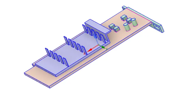
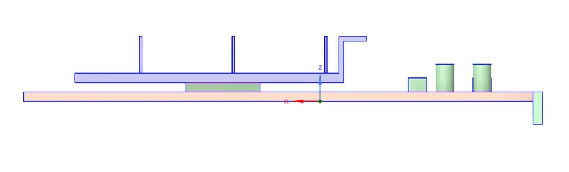
- The graphic card geometry is imported in "SpaceClaim".
- All the discrete components are selected and shared using "share" command under "workbench" tab. This usually helps in building "conformal mesh", which is important to share information within discrete components. Especially in Conjugate Heat Transfer (CHT) analysis it is mandatory to have conformal meshes.
1) Isometric View :
2) Side View :
2. Mesh :
Name sections :
- The geometrical set-up is updated in "Fluent Meshing". Initially, it is better to assign "Named Selections" before meshing the geometry. Because, this helps in body selection with no mistakes for meshing discrete components.
- Moreover the named selections helps in identifying components and faces to assign boundary condition in "Fluent" solver.
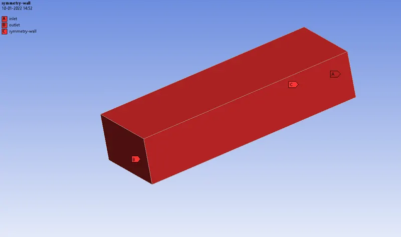
fig(a)
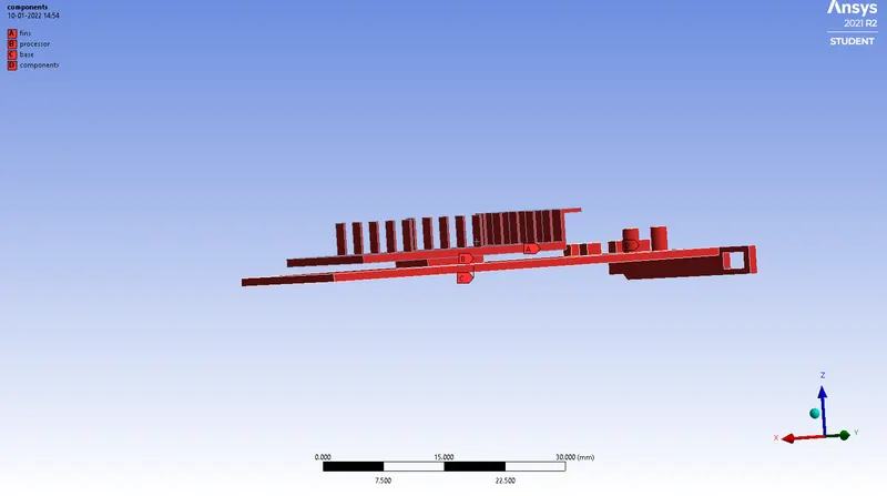
fig(b)
CASE 1 :
Mesh Details :
| Element Size | 6 mm |
| Body Sizing (Fins) | 0.51 mm |
| Body Sizing (Base) | 0.8 mm |
| Body Sizing (Processor) | 0.3 mm |
| Inflation | Processor walls |
| Y+ | 0.4 |
| Inflation type | Total Thickness |
| No. of Inflation Layers | 5 |
| Growth Rate | 1.2 |
| Maximum Thickness | 0.3 mm |
| Total number of cells | 5,02,367 |
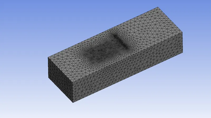
1.Enclosure :
2. Graphics card isometric view :
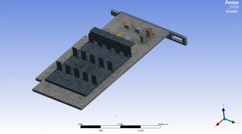
3. Processor inflation layer :
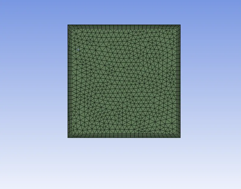
Here inflation layer is provided to the processor wall. Because here processor is the heat source which decipiate heat to the near by components. And the components near to the processor wall should also kept as fine as possible.
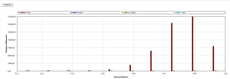
Mesh Quality :
SIMULATIONS :
|
SETUP |
||
|
Solver Type |
Pressure-Based |
|
|
Velocity Formulation |
Absolute |
|
|
Time |
|
|
|
Models |
Viscous model: K-omega SST Energy model: On |
|
|
Material |
Choose appropriate material properties for working fluid, fins, processor and printed circuit board from the table mentioned below |
|
|
Cell zones |
Fluid type: Air Solid: Al, Si, FR4 |
|
|
Boundaries |
Inlet : Inlet velocity = 5m/s Temperature = 300K Outlet : Outlet pressure = 0pa |
|
|
Reference values |
Area = 3.2e-5`m^2` Length = 0.008m |
|
|
Initialization |
Hybrid |
Material properties :
1. Working fluid : Air
| Density | 1.225 kg/`m^3` |
| Specific Heat | 1006.43 J/kgK |
| Thermal Conductivity | 0.0242 W/mk |
| Dynamic Viscosity | 1.7894`e^-5`kg/ms |
2. Solid Material for Fins : Aluminium
| Density | 2719 kg/`m^3` |
| Specific Heat at Const. Pressure | 871 J/kgK |
| Thermal conductivity | 202.4 W/mk |
3. Solid Material for processor : Silicon
| Density | 2330 kg/`m^3` |
| Specific Heat at Const. Pressure | 810 J/kgK |
| Thermal conductivity | 156 W/mk |
4. Solid Material for Printed Circuit Board Base : Flame Retardant (FR4)
| Density | 1910 kg/`m^3` |
| Specific Heat at Const. Pressure | 600 J/kgK |
| Thermal conductivity | 0.35 W/mk |
A] Scaled Residuals :
B] Report plot (Surface HTC - Processor wall) :
C] Contours :
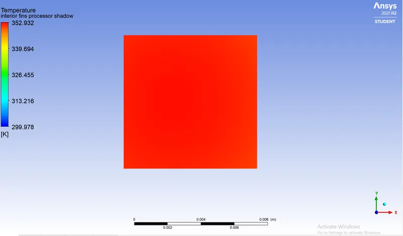
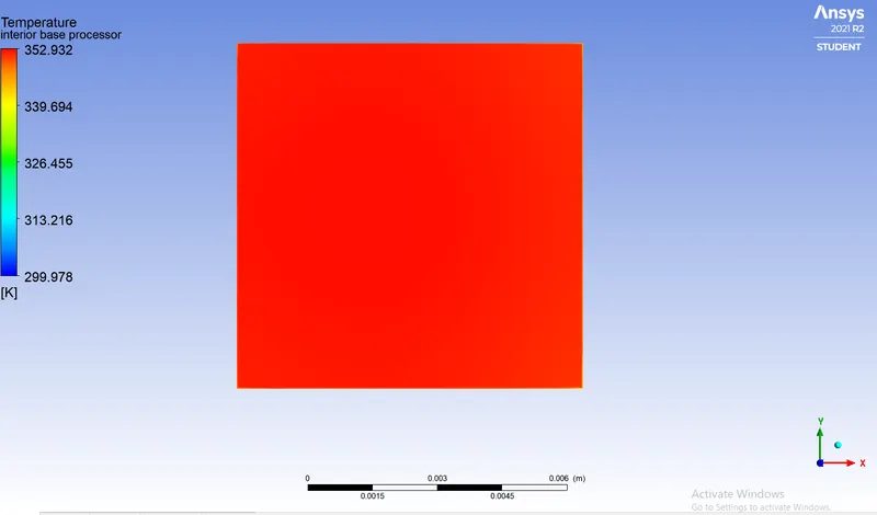
1. Temperature :
a) Processor face in contact with the fins :
b) Processor face in contact with the PCB base :
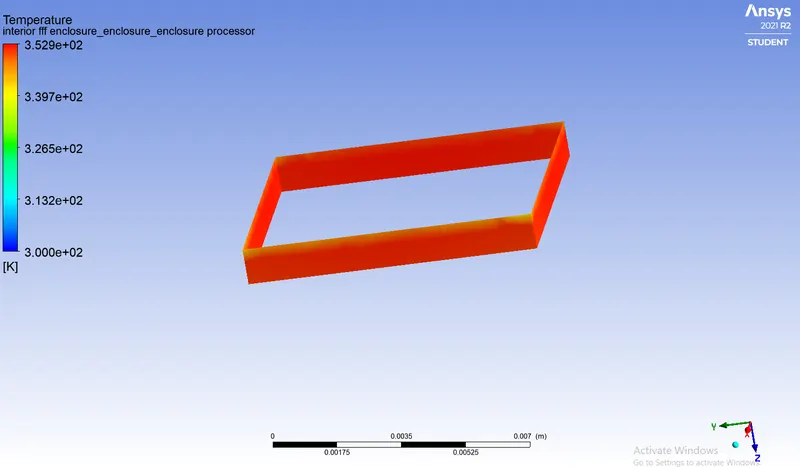
c) Processor walls exposed to forced air circulation :
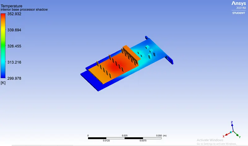
d) Graphic Card Set-up (Isometric View) :
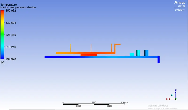
e) Graphic Card Set-up (Side View) :
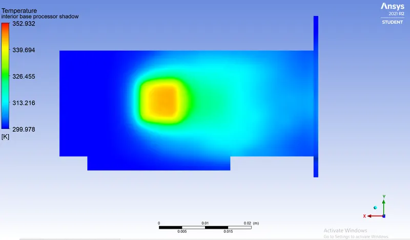
f) Temperature distribution over bottom of the PCB base :
2. Velocity :
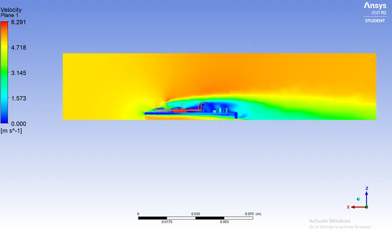
a) Velocity Contour :
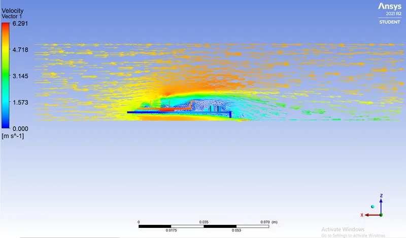
b) Velocity Vector plot :
3. Heat Transfer Coefficient :
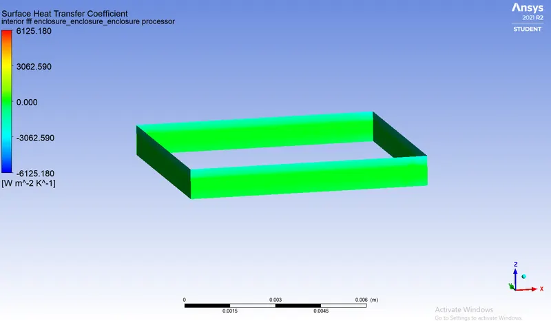
a) Processor walls :
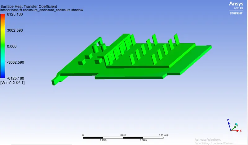
b) Graphic Card Set-up :
CASE 2 :
Mesh Details :
| Element Size | 6 mm |
| Body Sizing (Fins) | 0.51 mm |
| Body Sizing (Base) | 0.8 mm |
| Body Sizing (Processor) | 0.3 mm |
| Inflation | Processor walls |
| Y+ | 0.4 |
| Inflation type | Total Thickness |
| No. of Inflation Layers | 5 |
| Growth Rate | 1.2 |
| Maximum Thickness | 0.5 mm |
| Total number of cells | 5,01,064 |
1.Enclosure :
2. Graphics card isometric view :
3. Processor inflation layer :
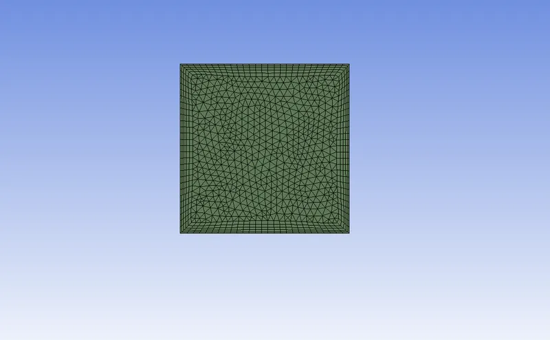
Here inflation layer is provided to the processor wall. Because here processor is the heat source which decipiate heat to the near by components. And the components near to the processor wall should also kept as fine as possible.
Mesh Quality :
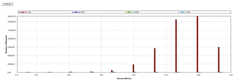
SIMULATIONS :
|
SETUP |
||
|
Solver Type |
Pressure-Based |
|
|
Velocity Formulation |
Absolute |
|
|
Time |
|
|
|
Models |
Viscous model: K-omega SST Energy model: On |
|
|
Material |
Choose appropriate material properties for working fluid, fins, processor and printed circuit board from the table mentioned below | |
|
Cell zones |
Fluid type: Air Solid: Al, Si, FR4 |
|
|
Boundaries |
Inlet : Inlet velocity = 3m/s Temperature = 300K Outlet : Outlet pressure = 0pa |
|
|
Reference values |
Area = 3.2e-5`m^2` Length = 0.008m |
|
|
Initialization |
Hybrid |
Material properties :
1. Working fluid : Air
| Density | 1.225 kg/`m^3` |
| Specific Heat | 1006.43 J/kgK |
| Thermal Conductivity | 0.0242 W/mk |
| Dynamic Viscosity | 1.7894`e^-5`kg/ms |
2. Solid Material for Fins : Aluminium
| Density | 2719 kg/`m^3` |
| Specific Heat at Const. Pressure | 871 J/kgK |
| Thermal conductivity | 202.4 W/mk |
3. Solid Material for processor : Silicon
| Density | 2330 kg/`m^3` |
| Specific Heat at Const. Pressure | 810 J/kgK |
| Thermal conductivity | 156 W/mk |
4. Solid Material for Printed Circuit Board Base : Flame Retardant (FR4)
| Density | 1910 kg/`m^3` |
| Specific Heat at Const. Pressure | 600 J/kgK |
| Thermal conductivity | 0.35 W/mk |
A] Scaled Residuals :
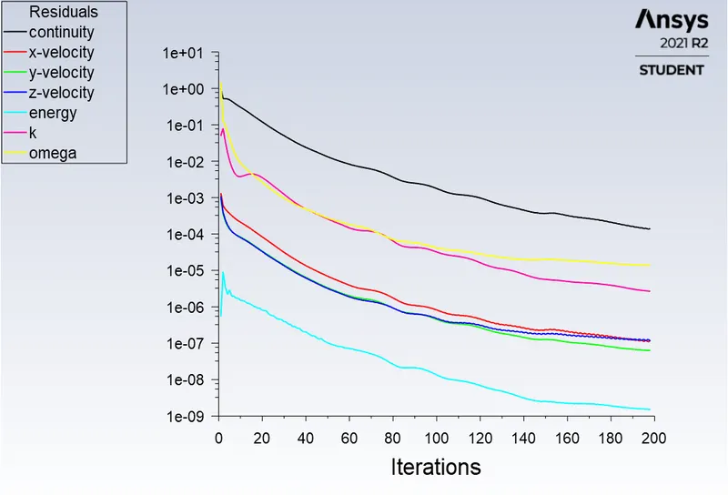
B] Report plot (Surface HTC - Processor wall) :
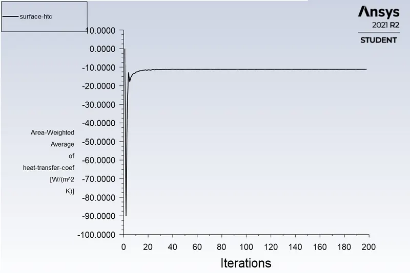
C] Contours :
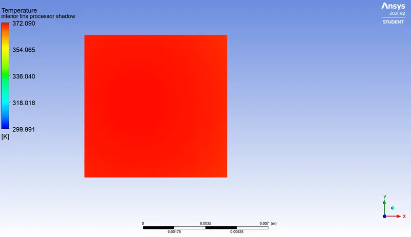
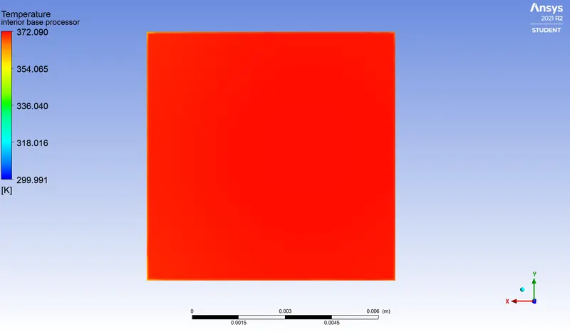
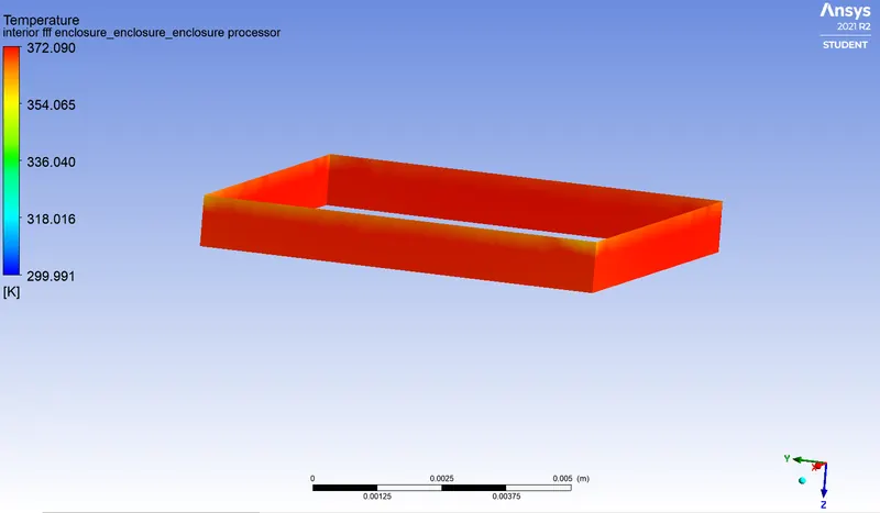
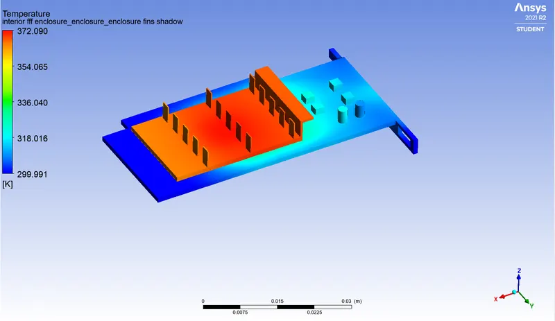
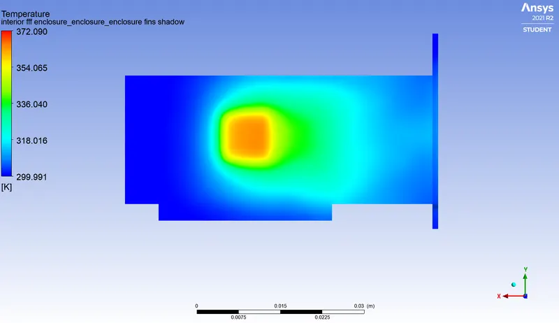
1. Temperature :
a) Processor face in contact with the fins :
b) Processor face in contact with the PCB base :
c) Processor walls exposed to forced air circulation :
d) Graphic Card Set-up (Isometric View) :
e) Graphic Card Set-up (Side View) :
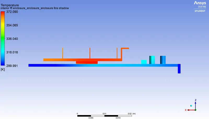
f) Temperature distribution over bottom of the PCB base :
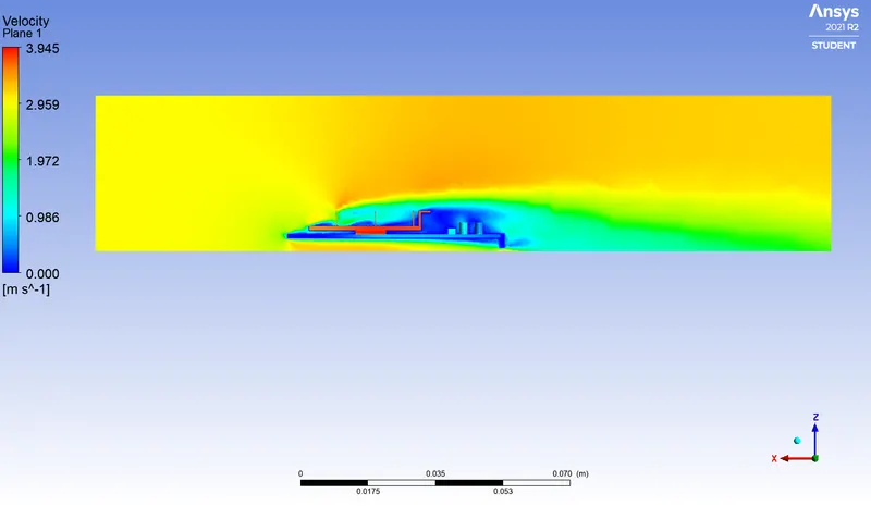
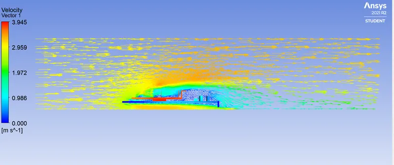
2. Velocity :
a) Velocity Contour :
b) Velocity Vector plot :
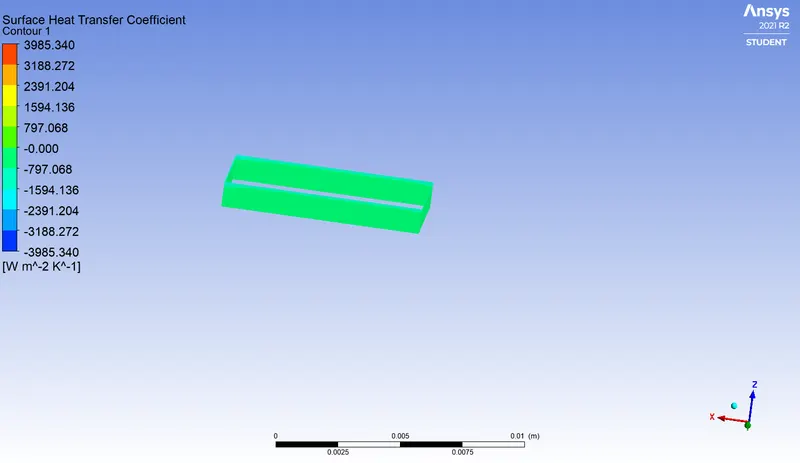
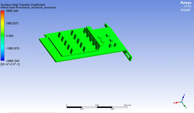
3. Heat Transfer Coefficient :
a) Processor walls :
b) Graphic Card Set-up :
CASE 3 :
CASE 1 :
Mesh Details :
| Element Size | 6 mm |
| Body Sizing (Fins) | 0.51 mm |
| Body Sizing (Base) | 0.8 mm |
| Body Sizing (Processor) | 0.3 mm |
| Inflation | Processor walls |
| Y+ | 0.4 |
| Inflation type | Total Thickness |
| No. of Inflation Layers | 5 |
| Growth Rate | 1.2 |
| Maximum Thickness | 1 mm |
| Total number of cells | 4,97,800 |
1.Enclosure :
2. Graphics card isometric view :
3. Processor inflation layer :
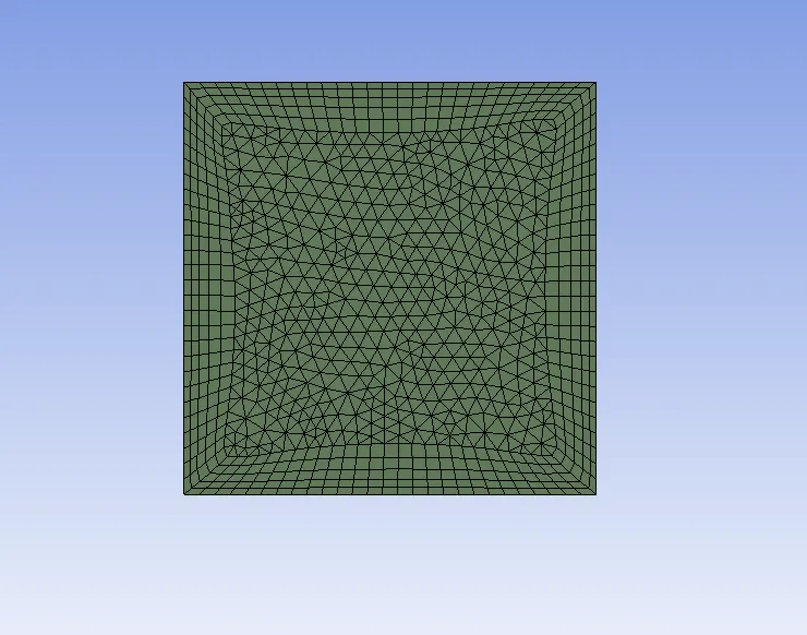
Here inflation layer is provided to the processor wall. Because here processor is the heat source which decipiate heat to the near by components. And the components near to the processor wall should also kept as fine as possible.
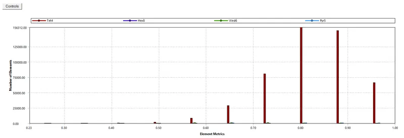
Mesh Quality :
SIMULATIONS :
|
SETUP |
||
|
Solver Type |
Pressure-Based |
|
|
Velocity Formulation |
Absolute |
|
|
Time |
|
|
|
Models |
Viscous model: K-omega SST Energy model: On |
|
|
Material |
Choose appropriate material properties for working fluid, fins, processor and printed circuit board from the table mentioned below | |
|
Cell zones |
Fluid type: Air Solid: Al, Si, FR4 |
|
|
Boundaries |
Inlet : Inlet velocity = 1m/s Temperature = 300K Outlet : Outlet pressure = 0pa |
|
|
Reference values |
Area = 3.2e-5`m^2` Length = 0.008m |
|
|
Initialization |
Hybrid |
Material properties :
1. Working fluid : Air
| Density | 1.225 kg/`m^3` |
| Specific Heat | 1006.43 J/kgK |
| Thermal Conductivity | 0.0242 W/mk |
| Dynamic Viscosity | 1.7894`e^-5`kg/ms |
2. Solid Material for Fins : Aluminium
| Density | 2719 kg/`m^3` |
| Specific Heat at Const. Pressure | 871 J/kgK |
| Thermal conductivity | 202.4 W/mk |
3. Solid Material for processor : Silicon
| Density | 2330 kg/`m^3` |
| Specific Heat at Const. Pressure | 810 J/kgK |
| Thermal conductivity | 156 W/mk |
4. Solid Material for Printed Circuit Board Base : Flame Retardant (FR4)
| Density | 1910 kg/`m^3` |
| Specific Heat at Const. Pressure | 600 J/kgK |
| Thermal conductivity | 0.35 W/mk |
A] Scaled Residuals :
B] Report plot (Surface HTC - Processor wall) :
C] Contours :
1. Temperature :
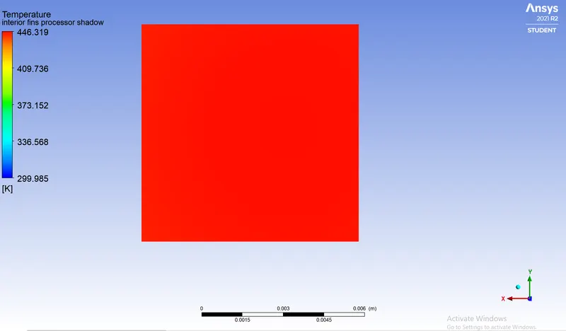
a) Processor face in contact with the fins :
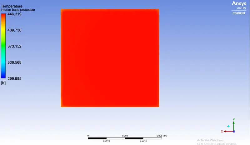
b) Processor face in contact with the PCB base :
c) Processor walls exposed to forced air circulation :

d) Graphic Card Set-up (Isometric View) :
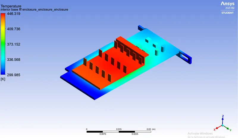
e) Graphic Card Set-up (Side View) :
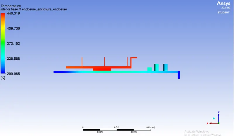
f) Temperature distribution over bottom of the PCB base :
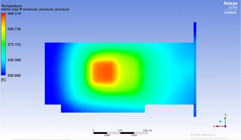
2. Velocity :
a) Velocity Contour :
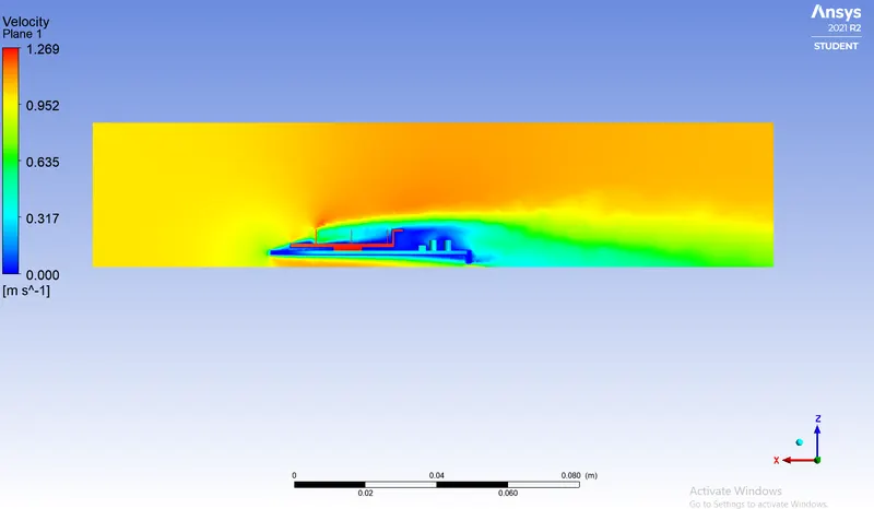
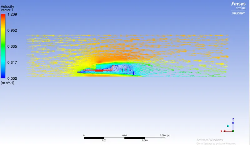
b) Velocity Vector plot :
3. Heat Transfer Coefficient :
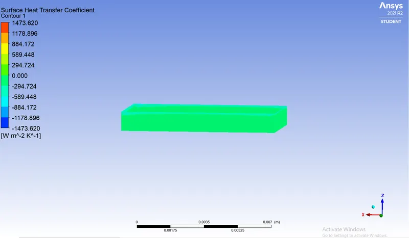
a) Processor walls :
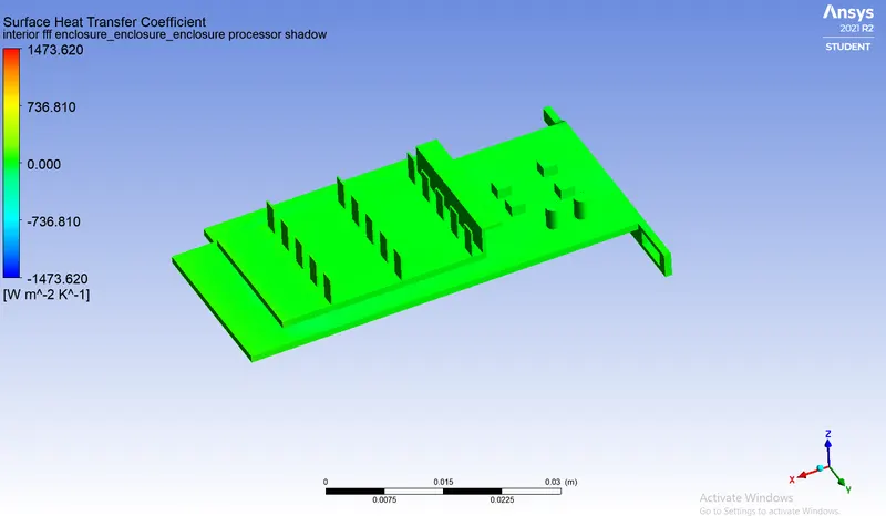
b) Graphic Card Set-up :
Observation Table :
A] Processor Walls :
| Cases | Air velocity (m/s) |
Average Temperature (K) |
Maximum Temperature (K) |
Average Surface Heat Transfer Coefficient (W/`m^2 K`) |
Minimum Surface Heat Transfer Coefficient (W/`m^2 K`) |
Maximum Surface Heat Transfer Coefficient (W/`m^2 K`) |
| Case 1 | 1 | 445.38 | 446.12 | 6.036 | 0.6432 | 30.414 |
| Case 2 | 3 | 371.18 | 371.85 | 11.173 | 1.023 | 52.469 |
| Case 3 | 5 | 352.03 | 352.68 | 18.906 | 1.284 | 80.938 |
B] Fins :
| Cases | Air velocity (m/s) |
Average Temperature (K) |
Maximum Temperature (K) |
Average Surface Heat Transfer Coefficient (W/`m^2 K`) | Minimum Surface Heat Transfer Coefficient (W/`m^2 K`) | Maximum Surface Heat Transfer Coefficient (W/`m^2 K`) |
| Case 1 | 1 | 442.05 | 446.036 | 19.235 | 0.0657 | 201.314 |
| Case 2 | 3 | 367.88 | 371.79 | 41.19 | 0.3512 | 234.69 |
| Case 3 | 5 | 344.343 | 352.636 | 57.662 | 0.4883 | 362.754 |
Conclusion :
- We conducted numerical simulations for heat transfer performance that occurs via conduction and convection modes.
- Conduction occurs in GPU chip to heat sink due to the GPU chip and the other component in contact with the heat sink. Convection occurs due to the heat transfer from the heat sink to the air via air inlet and outlet.
- For conduction the higher volume of the area, the higher the rate of heat transfer.
- For convection, the rate of heat transfer via convection highly depends on the air velocity. The coeffcient of heat convection is proportional to the air velocity. Higher the air velocity, the higher wiil be the heat transfer coeffcient via convection, and the higher the rate of heat transfer.
Reference :
https://computerinfobits.com/how-much-energy-do-gaming-computers-use/
https://www.scribd.com/document/408182531/CFD-Analysis-of-Graphics-card-by-Conjugate-heat-transfer