Week 6 - CHT Analysis on a Graphics card
Aim:
To perform a steady-state conjugate heat transfer analysis on a model of a graphics card
Introduction:
Conjugate heat transfer analysis means a combination of heat transfer in solids and liquids. In solid heat transfer takes place due to conduction and in liquid, the heat transfer will take place due to convection.
CHT is used in various applications to bring an optimized design, in some complex designs this is carried out to make the life span of the product increase. It is also accurate and easier to do than to conduct it experimental analysis which can take more time and the cost will also be higher.
Some of the common applications where CHT is used are HVAC systems, Electronic devices, Automotive parts, Power plants, Burners and Combusters, etc.
Pre-processing:
Geometry
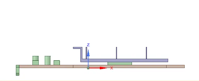
The graphics card with various components like a processor, fins, etc is imported to the workbench
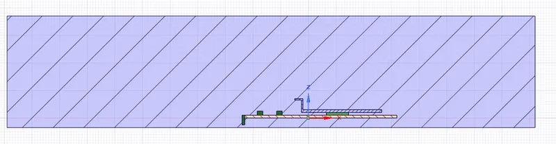
An enclosure around the card is created for fluid flow to occur
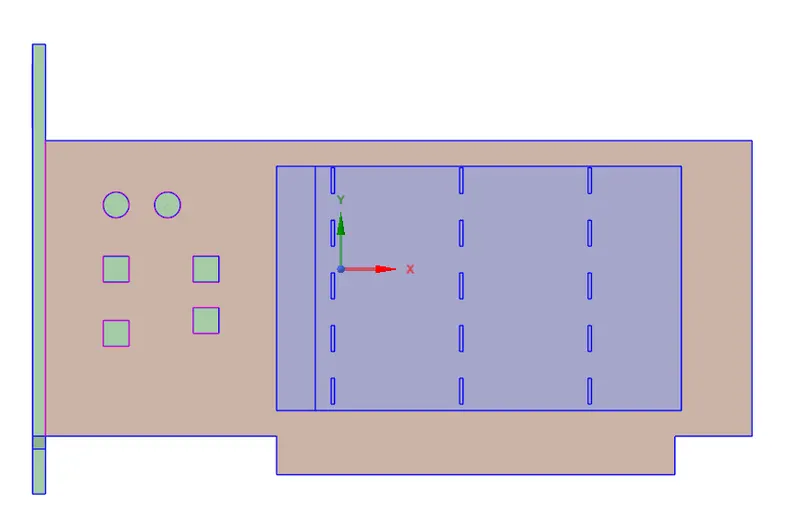
Then using the share option all the edges and faces are selected to obtain a conformal mesh.
Meshing
Now, named sections are created to apply boundary conditions
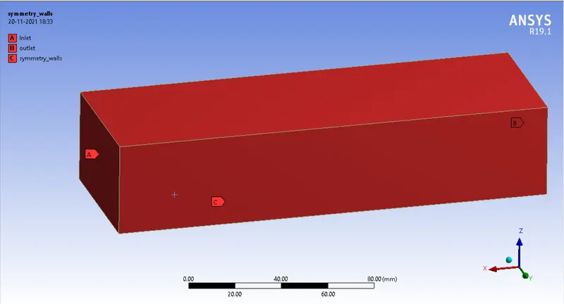
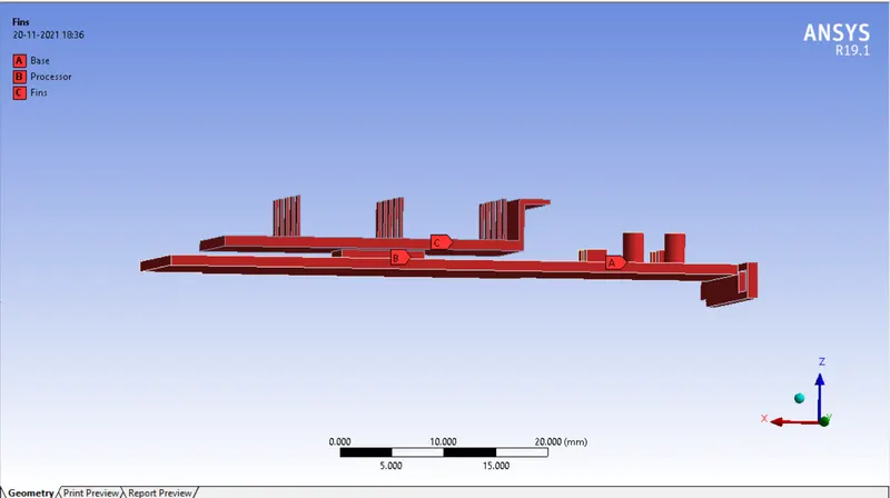
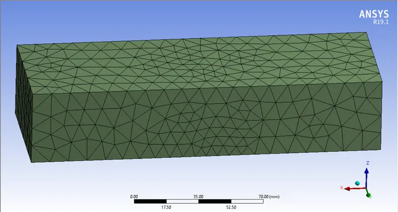
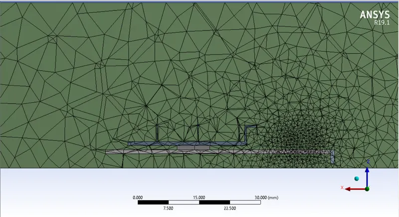
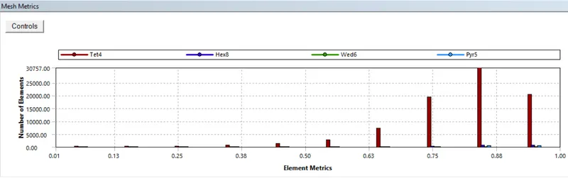
Then a baseline mesh is generated with element size = 10 mm
Setup
Steady-state simulation is carried with energy equation on

Different material is applied for different zones
Base = titanium
Fins = Aluminium
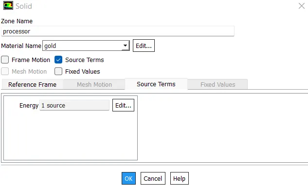
Processor = Gold
A source term is added for the processor with a value of 10 Watts
Boundary conditions are given
for inlet = velocity 1 m/s
outlet = gage pressure 0
Results:
Case 1
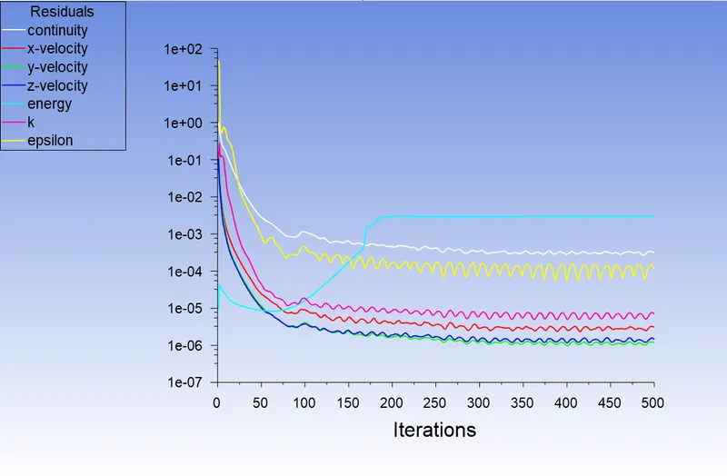
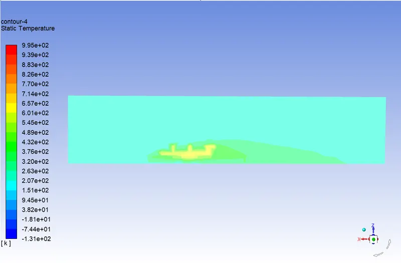
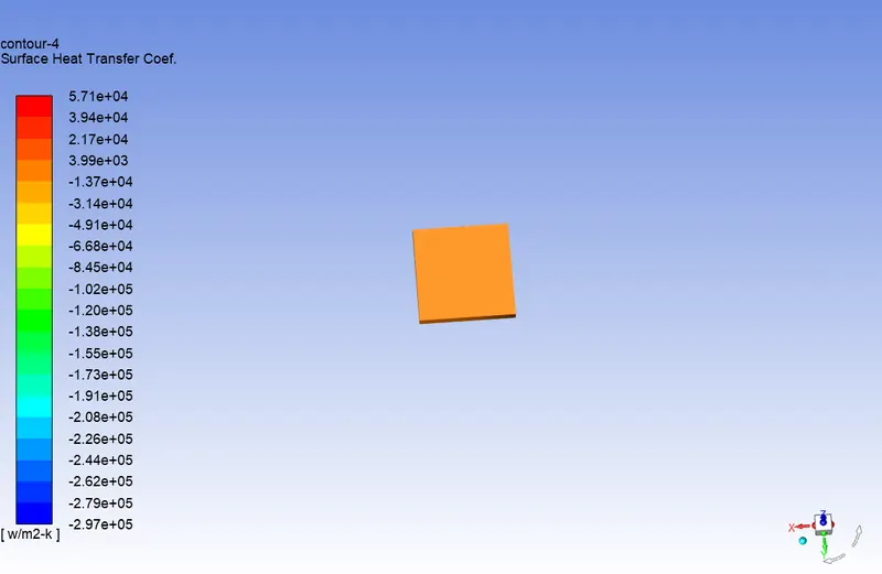
Baseline mesh with velocity 1 m/s
Residual plot
Temperature Distribution
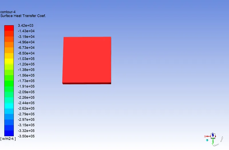
Heat Transfer Coefficient
Case 2
Refined Mesh with velocity 1m/s
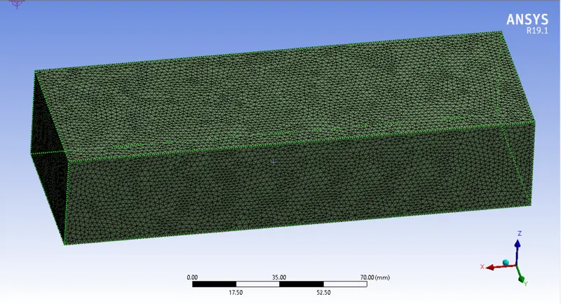
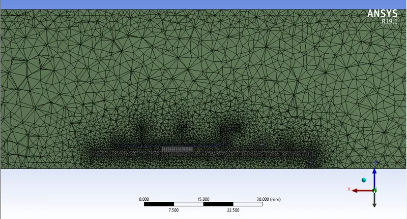
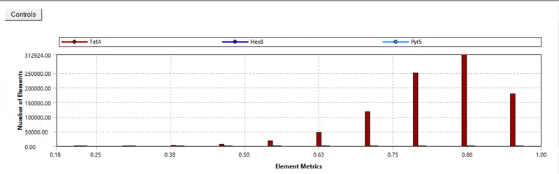
Added an body sizing for the graphics card area to capture the effect of conduction and convection more properly, the element size was given as 0.5 mm
For the enclosure the size was given as 2 mm as it is not our main focus in this simulation.
Residual plot
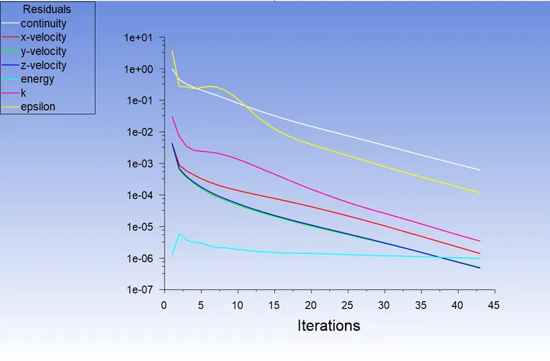
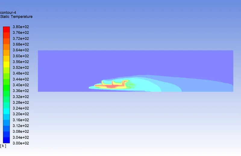
Temperature Distribution
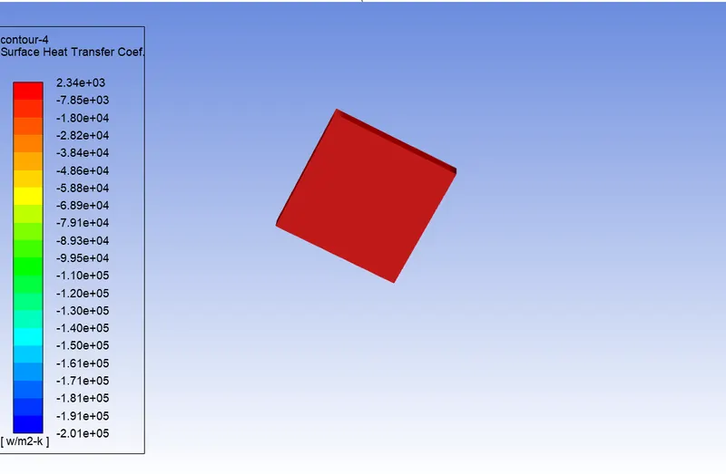
Heat Transfer Coefficient
Case 3
Refined mesh with velocity - 2.5 m/s
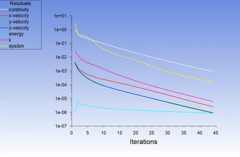
Residual plot
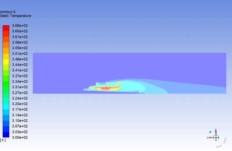
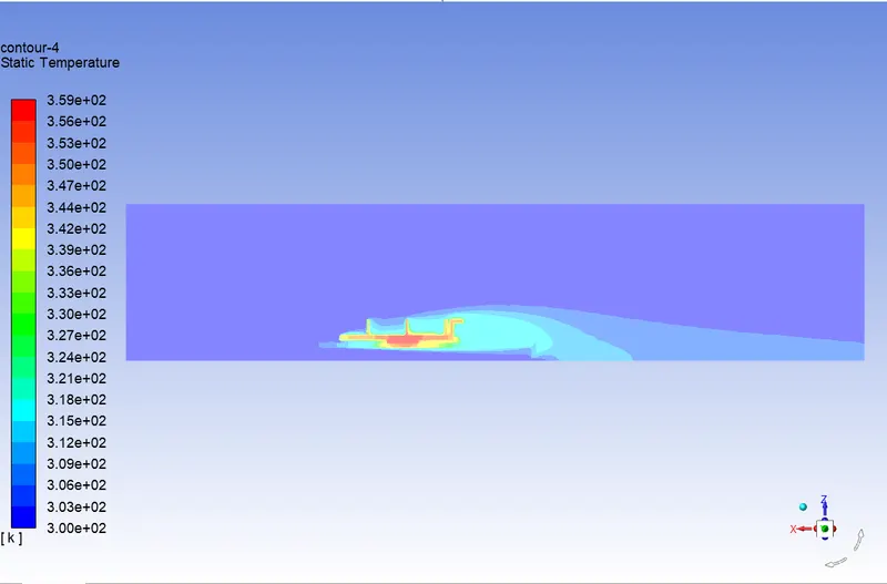
Temperature Distribution
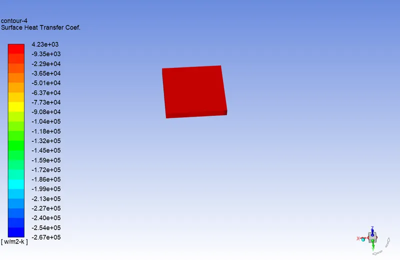
Heat Transfer Coefficient
Case 4
Refined mesh with velocity - 5 m/s
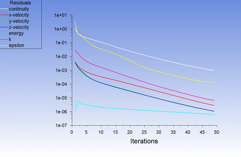
Residual plot
Temperature Distribution
Heat Transfer Coefficient
Conclusions:
Baseline Mesh vs Refined Mesh
In the baseline mesh the conduction and convection was not able to be captured perfectly hence the maximum temperature was very high (559 K) whereas for the same velocity for a refined mesh the temperature was much lesser with 380 K.So we can say that both conduction and convection were captured accurately in Refined Mesh.
Velocity variation
| Velocity (m/s) | Maximum temperature of Processor(K) | Maximum HTC of Processor (W/m2-K) |
| 1 | 380.1 | 3762.452 |
| 2.5 | 368.163 | 4793.857 |
| 5 | 359.348 | 5944.671 |
So as we can see from the above table as the velocity increases the maximum temperature has been reduced significantly which is the logical result expected , as the temperature has decreased its shows that the rate of convection has increased so according to newtons law of cooling Heat transfer coefficient(HTC) also increased.