Week 6 - CHT Analysis on a Graphics card
Conjugate Heat Transfer (CHT)
Conjugate heat transfer is defined as the heat transfer between two domains by exchange of thermal energy. For a system the thermal energy available is defined by its temperature and the movement of thermal energy is defined by its heat flux through the outer walls. Heat transfer in solid happens through conduction and through walls by convection and in liquid phase through convection.
CHT provides the temperature prediction and the hotspot regions at the solid-fluid interface and we can also predict the heat transfer accurately for example- Conduction through solids, convection through fluid and thermal radiation. It also provides the velocity and pressure distribution of fluid moving inside the solid. We can also use CHT in design optimization for improvement for heat transfer and cooling capacity.
- A video card (also called a graphics card, display card, graphics adapter, or display adapter) is an expansion card which generates a feed of output images to a display devices (such as a computer monitor).Most video cards are not limited to a 6 inch simple output. Their integrated graphics processor can perform additional processing, removing this task from the central processor of the computer.
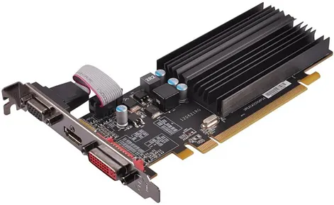
CASE SETUP IN ANSYS FLUENT:
- I) Introduction:
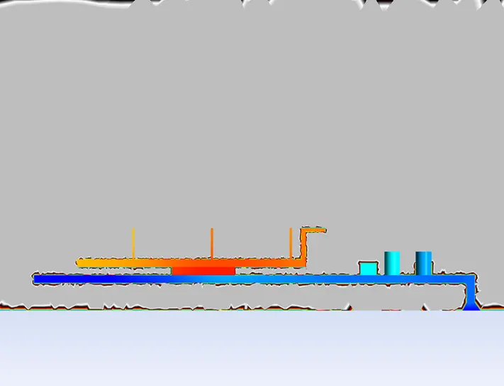
The physical model of the problem is as follows: A graphics card is kept inside an enclosure with moving air. The graphic card is made of multiple solid components that are defined in the next section. The heat transfer occurs as follows: The GPU of the graphic card generates heat. The Processor is in contact with the PCB and the heat sink. The PCB is of FR-4 material which is a composite material composed of woven fiberglass cloth with an epoxy resin binder that is a thermal resistor. Hence it does not conduct heat significantly. The heat is conducted to the heat sink. The fins of the heat sink increase the effective area of convective heat transfer. Forced convection occurs from the fins to the fluid. The HTC is determined wrt for different magnitudes of velocity.
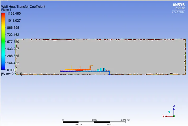
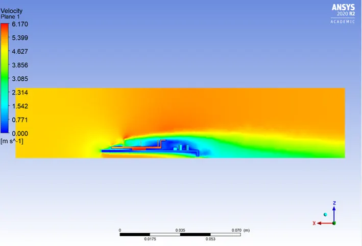
It is expected that with an increase in the magnitude of velocity, the HTC must increase and the temperature distribution must become more localized. Three cases involving different air velocities are simulated:
Case #1: Air velocity of 1 m/s.
Case #2: Air velocity of 3 m/s
Case #3: Air velocity of 5 m/s
- II) Geometry:
The physical model is shown below. The graphics card is a made-up CAD model that is imported to Spaceclaim in the .stl format. This made-up model contains the major components of a real graphics card- GPU, Fins, PCB, Memory Units, and Capacitors. The dimensions of the enclosure are (191 X 65 X 40.5) mm. The solid regions and the fluid regions are kept as separate components in Spaceclaim (shown below) so that Fluent does not consider all regions as a fluid region by default. The final topology is 'shared' using the Workbench --> Share option in order to create a Conformal mesh.
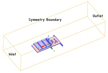
III) Meshing:
The base element size is given as 3 mm. Named selections are created on the enclosure and to different components of the Graphic card to specify the material. The named selection are as follows: Inlet, Symmetry and, Outlet on the enclosure; Processor, Fins, Base, Capacitor, Memory unit, and PCB on the graphic card.
Only the heat transfer at the macroscopic level is of interest. Hence the mesh is refined based on the total cell count and the ability to capture curvature. The temperature distribution and the HTC is to be determined on the surface of the graphics card. The Processor(heat source) is connected by both the PCB and the heat sink. Hence, these three components are refined to the maximum possible extent keeping the mesh of the enclosure relatively courser.
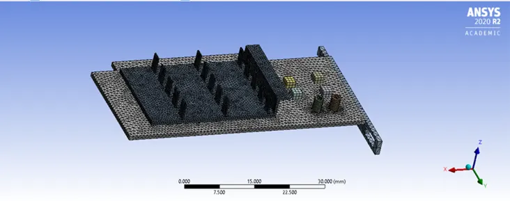
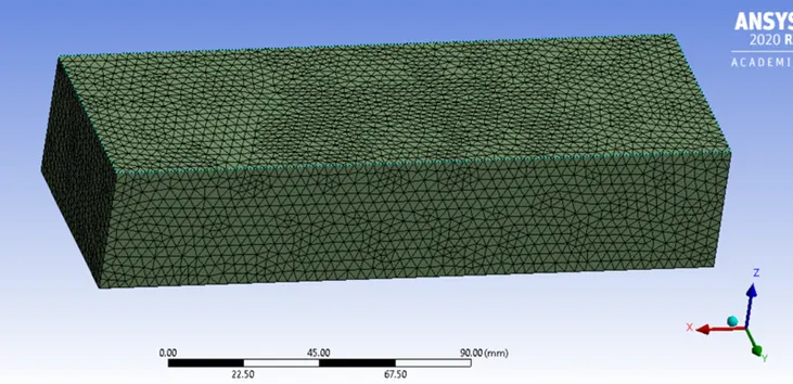
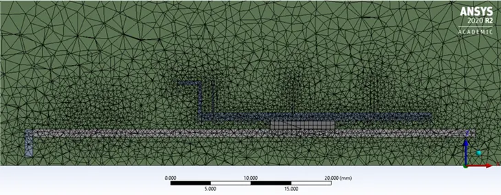
Mesh Body sizing is specified on the Processor, Fins, and PCB. The mesh sizes are shown below. The generated mesh is checked for conformity by creating a section plane. Shown below are the images depicting the mesh on the Graphics card and the conformity of the mesh between the solid and the fluid regions respectively.
INITIAL TEST - BASELINE SETUP:
A basic mesh is genertaed using the standard values recommended by Ansys. This mesh is used to obtain an initial solution which will help us to determine the location where mesh refinement is required.
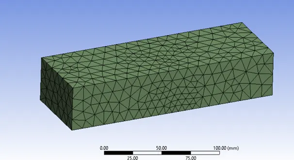
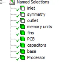
1.Element Order: Linear
2.Element size: Default
3.Number of Nodes: 12627
4.Number of Elements: 52375
Fluent:
- A pressure-based, steady-state solver is used.
- The energy equation is switched on.
- The Standard K-epsilon turbulence model is selected.
- The solid zones and fluid zones are defined in 'cell zones' under the Physics tab.
- Materials are chosen in the 'Create/Edit Material'. The materials are then specified to the different components of the Graphics card. The table of materials for the corresponding solid parts are shown below. The material properties are constant and do not change under any condition.
- Since there is an enclosure, each zone in this CHT simulation has a two-sided wall meaning the mesh is present on both sides of the walls of any zone inside the enclosure. Hence, no specific convection/ conduction boundary condition needs to be specified. The heat source is specified on the Processor. The velocity at the Inlet of the enclosure is specified according to Case #1, #2, or #3. The outlet boundary is to pressure BC of 1 atm.
- The volume of the Processor is 64 mm^3. Considering a standard Nvidia GT 730 graphics card, its Thermal Design Point [TDP] i.e, the amount of heat that is generated by the Processor which is to be dissipated by the heat sink is 49 Watts. Fluent requires the heat generation term to be entered as a source term in W/m^3. This source term is specified on the Processor under 'Cell zones'.
The Heat generation rate is calculated as = 4964e−9=7.65e+8Wm34964e−9=7.65e+8Wm3
- The solution scheme is a 'Coupled' pressure velocity scheme.
- The solution is initialized using the Hybrid solver.
- The temperature contours, the temperature on Processor and Fins, Wall HTC on the surface of fins and Processor, are all set up under the 'results' tab.
RESULTS AND POST-PROCESSING:
- I) Convergence:
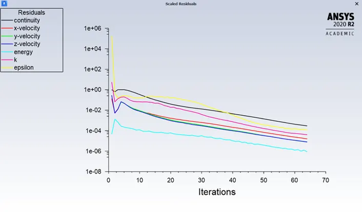
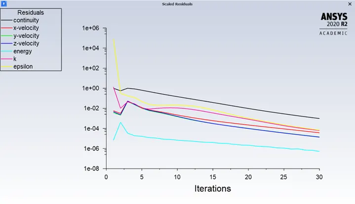
Shown below are the residual plots for all the cases. The simulation was set to run for 300 iterations but the solution attains convergence before. The plots are shown below.
Base Line:
RESIDUAL:
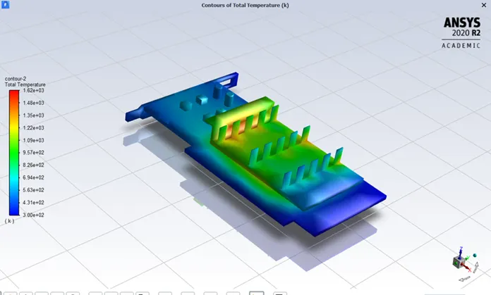
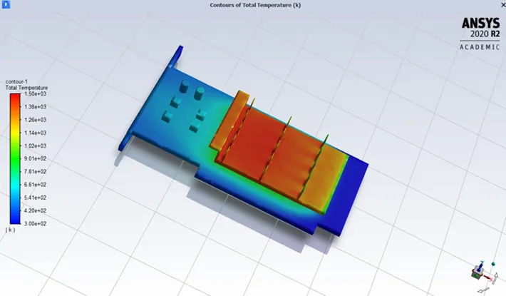
TOTAL TEMPERATURE:
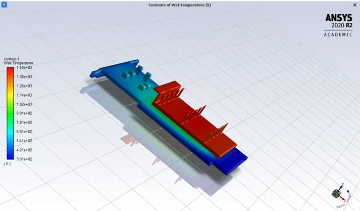
WALL TEMPERATURE:
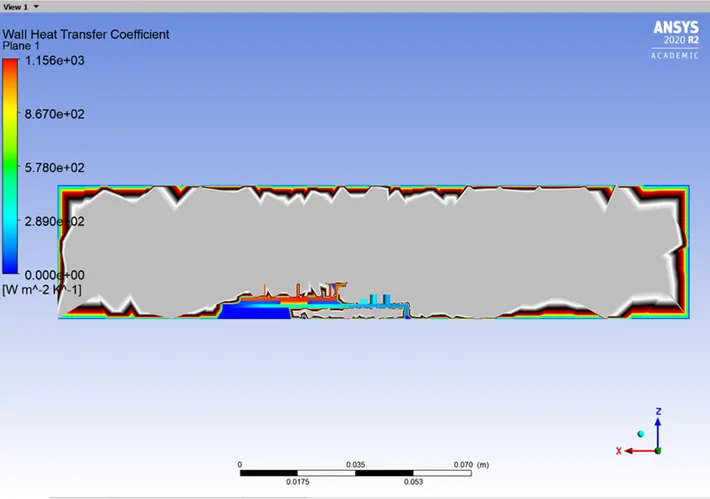
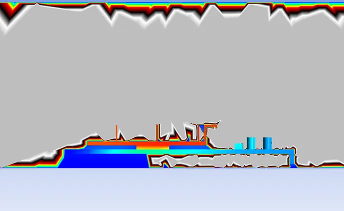
WALL HEAT TRANSFER COEFFICIENT:
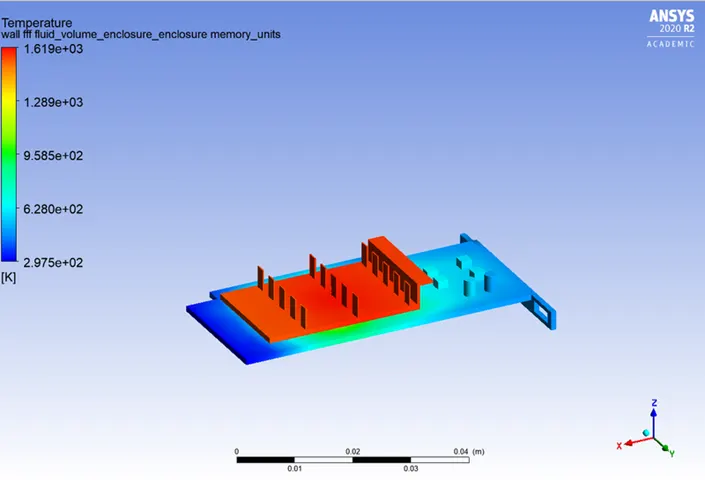
GLOBAL HOTSPOT REGION:
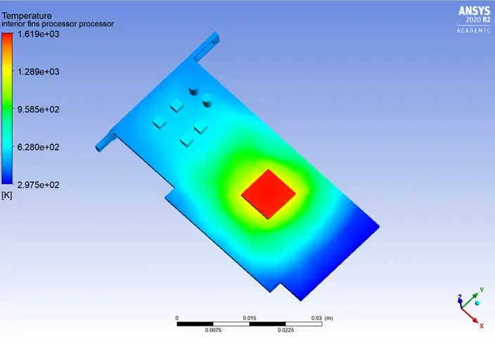
HOTSPOT AROUND PROCESSOR:
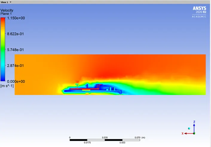
VELOCITY CONTOUR:
REFINED MESH:
Results are coarse in base line mesh. For getting fine result we choosed this mesh and we almost fully used academic licence limit.
The base element size is given as 3.1 mm
NODES - 88422
ELEMENTS - 499811

RESULTS AND POST-PROCESSING:
- I) Convergence:
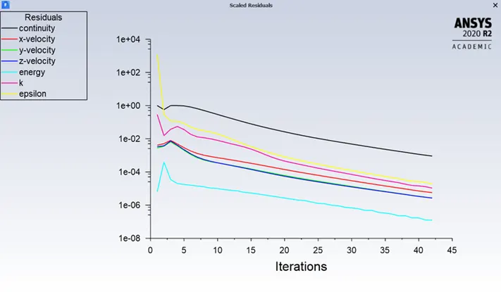
Shown below are the residual plots for all the cases. The simulation was set to run for 300 iterations but the solution attains convergence before. The plots are shown below.
CASE #1: V=1m/s
RESIDUALS:
TOTAL TEMPRATURE:
WALL TEMPERATURE:
Wall Heat Transfer Coefficient:
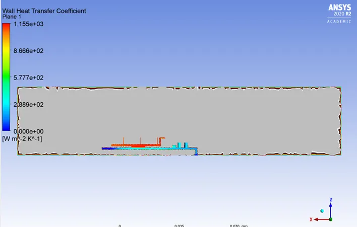
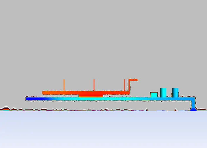
GLOBAL HOTSPOT REGION:
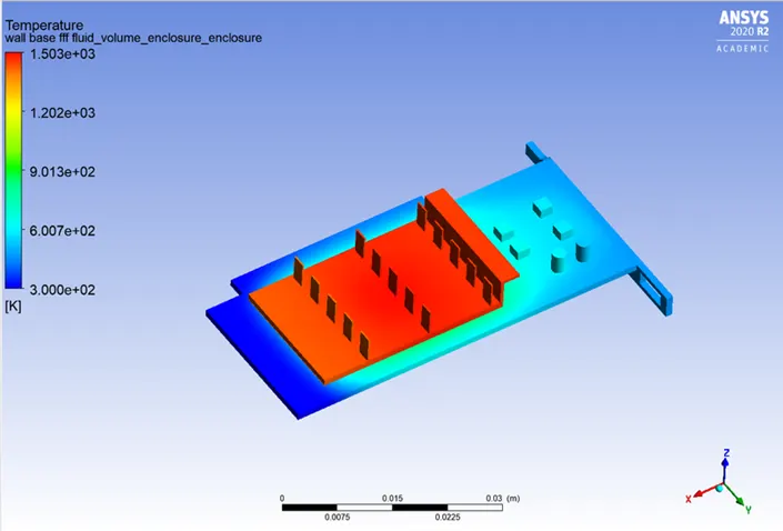
HOTSPOT AROUND PROCESSOR:
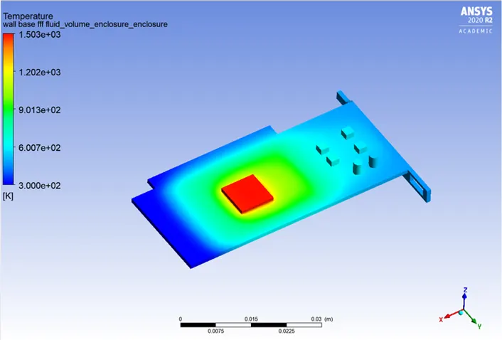
VELOCITY
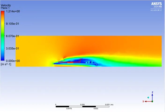
CASE #2 V=3m/s
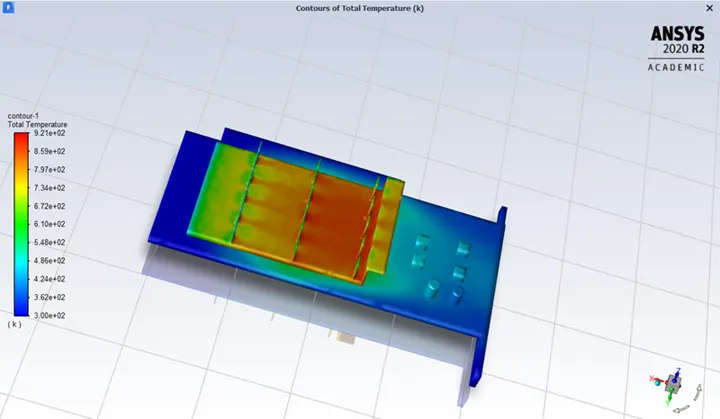
TOTAL TEMPERATURE:
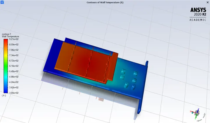
WALL TEMPERATURE
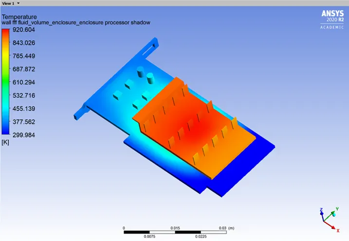
GLOBAL HOTSPOT REGION:
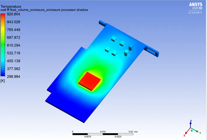
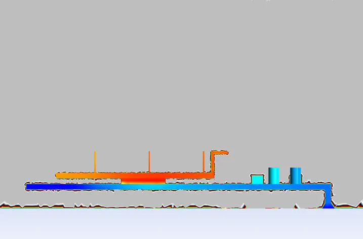
HOTSPOT AROUND PROCESSOR:
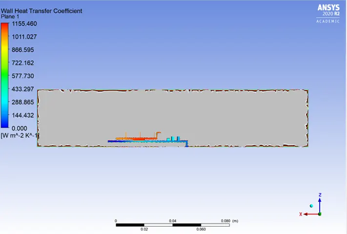
WALL HEAT TRANSFER COEFFICIENT:
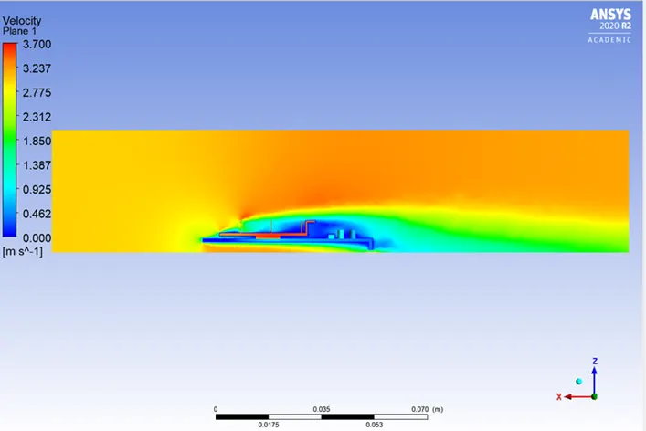
VELOCITY CONTOUR:
CASE #3 V=5 m/s
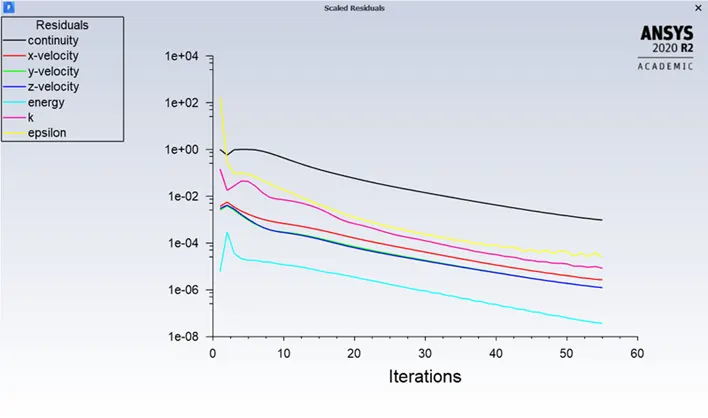
RESIDUALS:
TOTAL TEMPERATURE
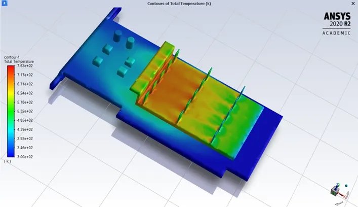
WALL TEMPERATURE:.
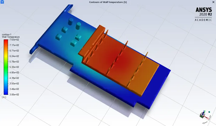
GLOBAL HOTSPOT REGION:
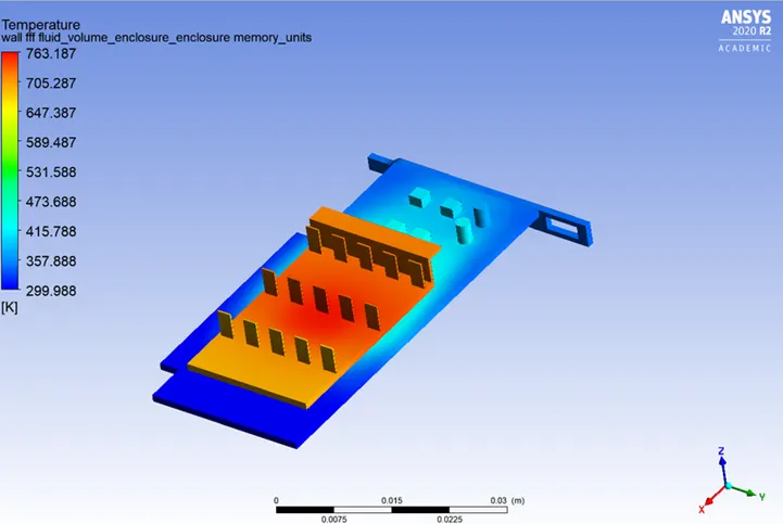
HOTSPOT AROUND PROCESSOR:
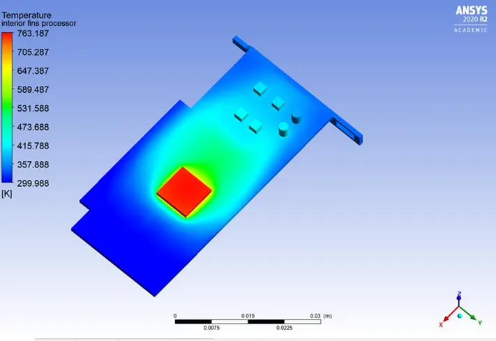
WALL HEAT TRANSFER COEFFICENT:
VELOCITY CONTOUR:
RESULTS:
|
Velocity[m/s] |
Temperature at Processor [k] |
HTC at Processor [Wm2.kWm2.k] |
Temperature at Fins [k] |
HTC at Fins [Wm2.kWm2.k] |
|
1 |
1494.78 |
410.767 |
1460.5 |
253.524 |
|
3 |
912.028 |
412.541 |
878.601 |
256.769 |
|
5 |
754.765 |
414.049 |
721.752 |
257.863 |
CONCLUSION
- As the number of elements increases the accurate results of temperature distribution is obtained
- From the above table it is fairly notable that, the net temperature of componenets of graphics card decreases with increase in inlet velocity.
- Hence it can be inferred that a higher inlet velocity results in better cooling and lower the average temperature thus keeping the components safe from damage.
- Furthermore, it can be observed that the temperature of components increases as the inlet velocity decreases from 5 m/s to 1m/s, also proving that higher velocity results in better cooling.