Week 6 - CHT Analysis on a Graphics card
AIM
To conduct a CHT analysis on a graphics card
OBJECTIVES
- Run the simulation by varying the velocity from 1m/sec to 5m/sec for at least 3 velocities and discuss the results.
- Find out the maximum temperature and heat transfer coefficient attained by the processor.
- Prove that the simulation has achieved convergence with appropriate images and plots.
- Identify potential hotspots on the model.
THEORY
Conjugate Heat Transfer (CHT)
The term Conjugate Heat Transfer (CHT) is used to describe processes that involve simultaneous energy exchange between the solid and fluid domains due to interaction between them and is frequently encountered in a variety of engineering applications such as internal combustion engines, turbo-machinery, heat exchangers, etc.
The Conjugate Heat Transfer (CHT) analysis type allows for the simulation of heat transfer between solid and fluid domains by exchanging thermal energy at the interfaces between them. Typical applications of this analysis type exist as, but are not limited to, the simulation of heat exchangers, cooling of electronic equipment, and general-purpose cooling and heating systems. Computational Fluid Dynamics (CFD) and more specifically conjugate heat transfer (CHT) analysis can accurately predict heat transfer by simultaneous solving all the relevant solid and flow field heat transfer processes.
It represents a class of multi-physics problems where fluid flow affects the thermal behaviour of structure, which in turn affects the fluid flow. For conjugate heat transfer analyses, the solid material conduction and the fluid convection are analysed simultaneously. The conductive heat transfer in a solid region is coupled to the convective heat transfer in a neighbouring fluid flow.
Graphics card
The graphics processing unit (GPU), also called graphics card or video card, is a specialized electronic circuit that accelerates the creation and rendering of images, video, and animations. It performs fast math calculations while freeing the CPU to perform other tasks. A heat sink is mounted on most modern graphics cards. A heat sink spreads out the heat produced by the graphics processing unit evenly throughout the heat sink and unit itself. The heat sink commonly has a fan mounted as well to cool the heat sink and the graphics processing unit.
As temperature increases, the performance of the graphics card drops causing the same to graphic performance and in an extreme case, causing a computer operations to stop. A heat sink is used to overcome the overheating issue of the graphics card. However, the transfer and flow of heat inside a computer case and distribution of temperature at the heat sink are unknown. Hence, a computational fluid dynamics (CFD) simulation is carried out to investigate and observe the
transfer of heat flow inside a computer case and heat sink in order to solve the graphics card overheating issue.
SIMULATION PROCEDURE
Open Ansys Workbench, select fluid flow(fluent) and create geometry in spaceclaim.
For conjugate heat transfer simulation, the mesh should be conformal. So that the fluid mesh and solid mesh should overlap each other.
For that enable share topology option.
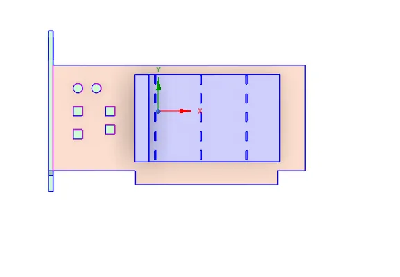
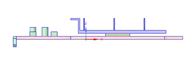
After creating geometry, close spacelaim then the next step is to create the mesh. Before meshing name the boundaries.
After completing meshing, Double click on setup to open CFD solver.
CFD Case Setup
- Pressure based solver and Absolute velocity is used.
- Steady-state Calculation is performed.
- Compressible fluid flow is chosen.
- Enable the energy equation.
- Viscous model- K-epsilon Realizable is used.
- Materials selected as Fluid-air; solid-[Fin-aluminium, base- copper, processor- gold]
- In cell zones a contant source term is added to the processor where the heat is generated.
Heat generated:
Heat generated is assumed to be 10W
The dimensions of the graphics card is 8 x 8 x 1 mm.
Heat generated per unit area = `10/(64*10^-9)W/m^3` = `156250000 W/m^3`
Results
Baseline mesh
element size = 2mm
No. of elements= 314305
Case 1
Inlet wind velocity = 1m/s
Mesh
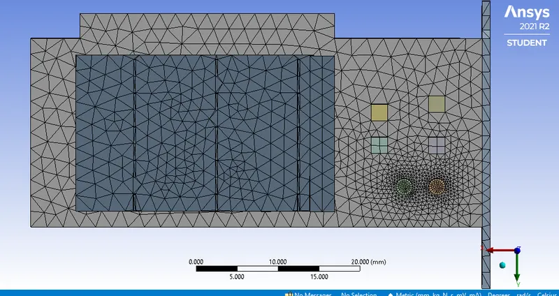
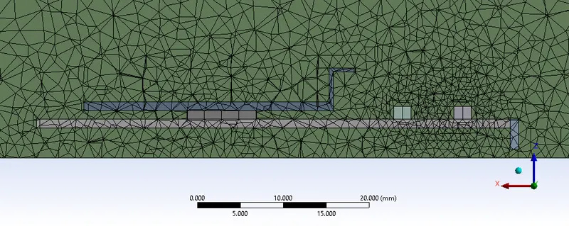
Element quality

Temperature contour
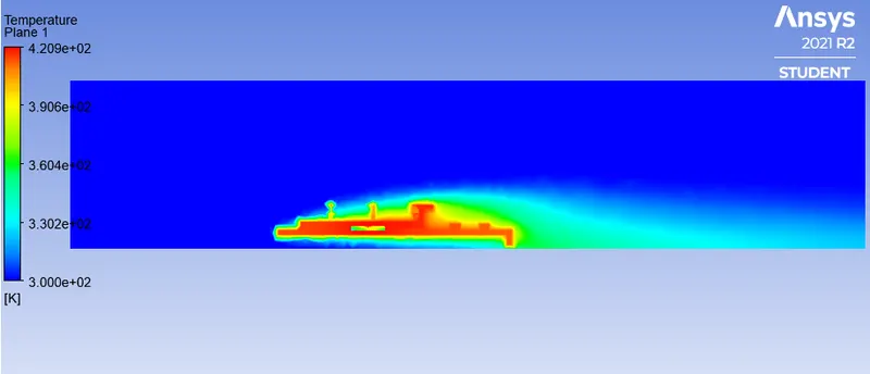
Temperature contour
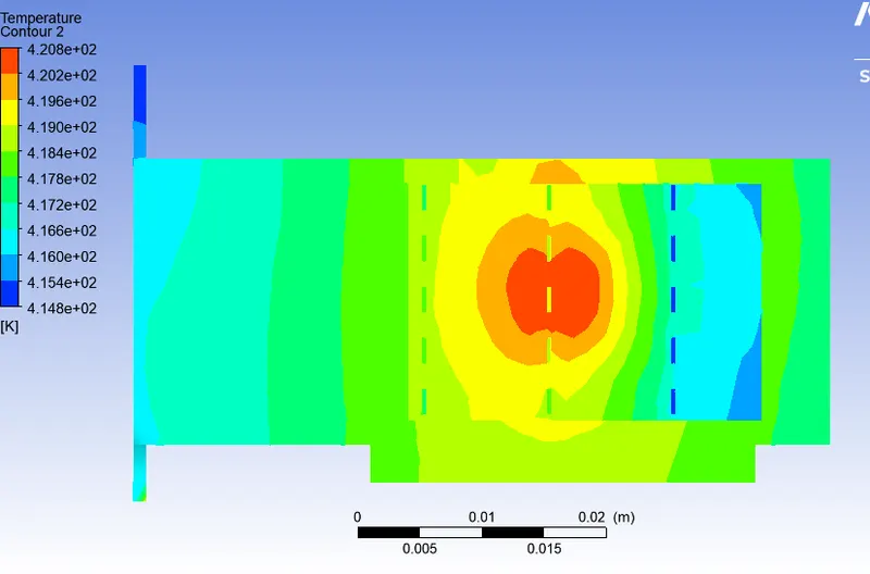
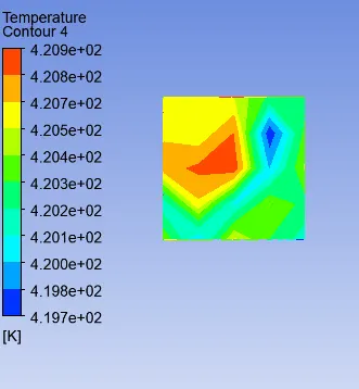
Temperature contour on processor
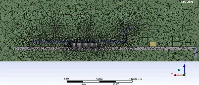
Refined mesh
Element size :
Enclosure = 3mm
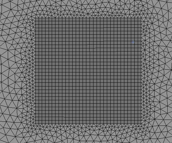
Processor body sizing = 0.25mm
Fin body sizing = 0.5mm
Base body sizing = 2mm
No. of elements= 493133
Case 2 : A
Inlet wind velocity = 1m/s
Mesh
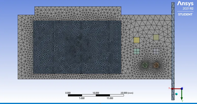
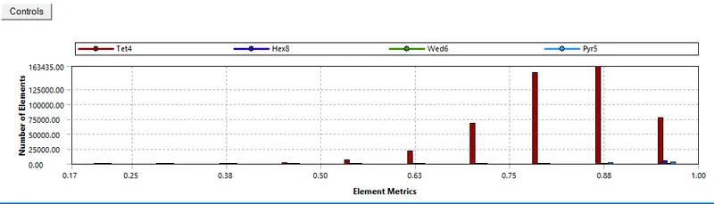
Element quality
Residual plot
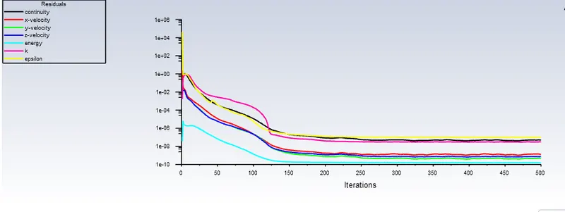
The simulation has converged after 250 iterations.
Temperature contour
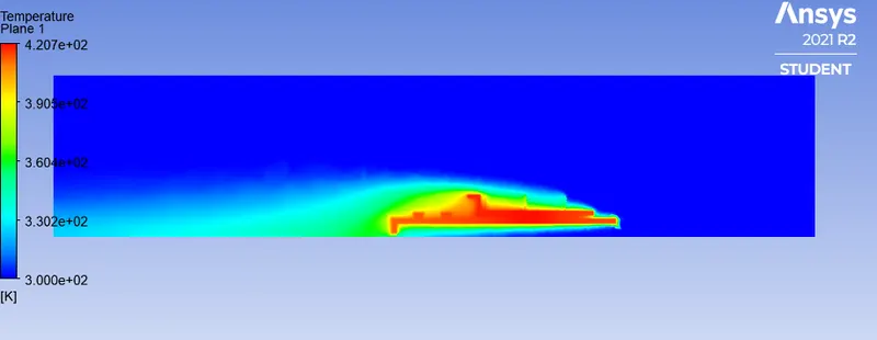
Temperature contour
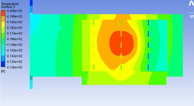
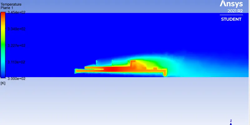
The heat is generated in the processor, from the processor heat is conducted into the base and the fin. Convection takes place from the components to the air. The fins close to the inlet has lower temperature compared to those at the back this is because as the wind passes through the fins it's velocity decreases, thus convection decreases.
Temperature contour on processor
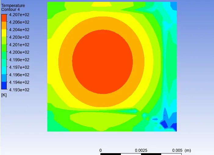
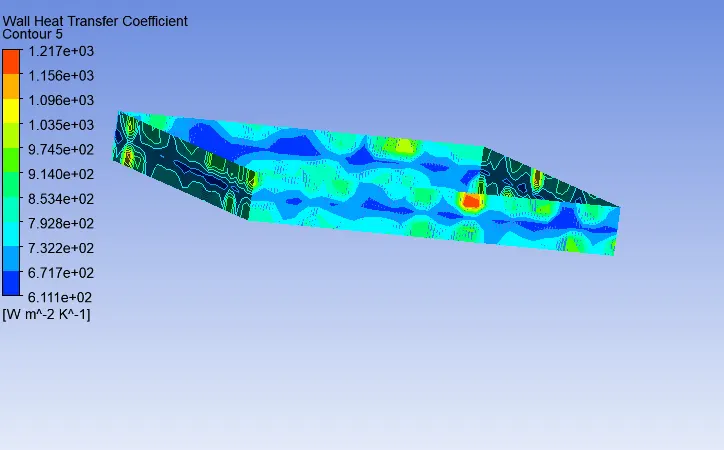
Wall heat transfer coeffecient attained by processor
Case 2 : B
Inlet wind velocity = 3m/s
Residual plot
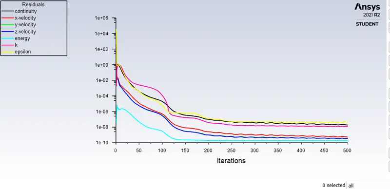
The simulation has converged after 300 iterations.
Temperature contour
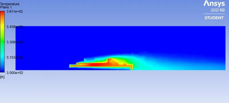
Temperature contour
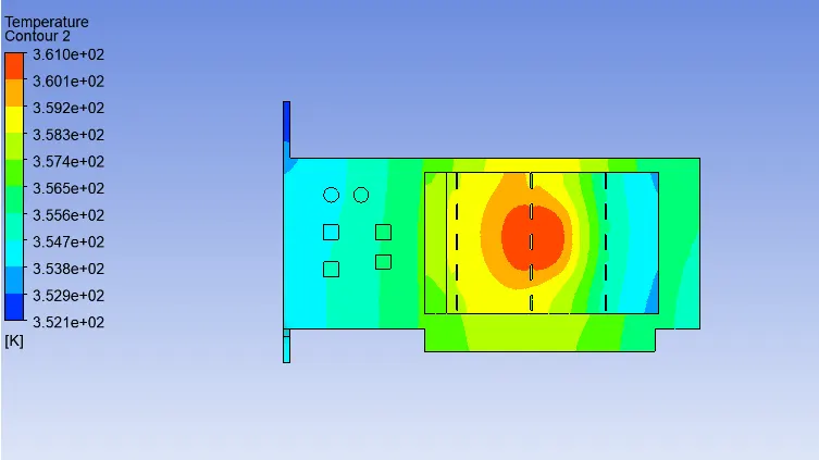
Temperature contour on processor
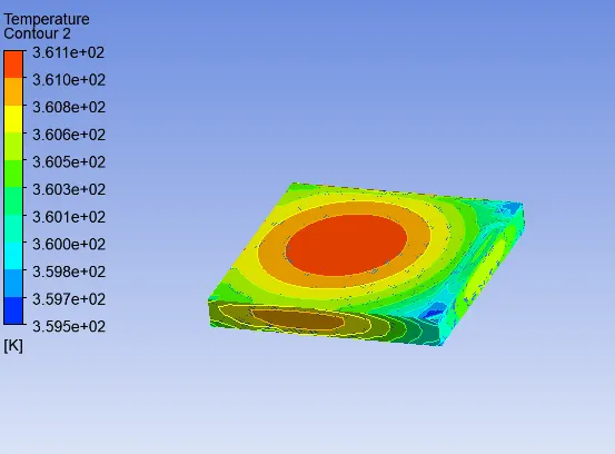
Wall heat transfer coeffecient attained by processor
Case 2 : C
Inlet wind velocity = 5m/s
Residual plot
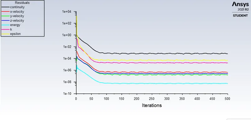
The simulation has converged after 200 iterations.
Temperature contour
Temperature contour
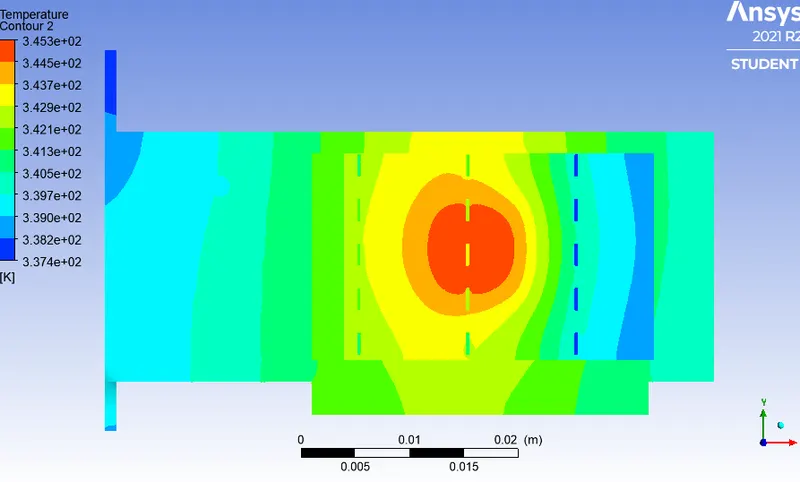
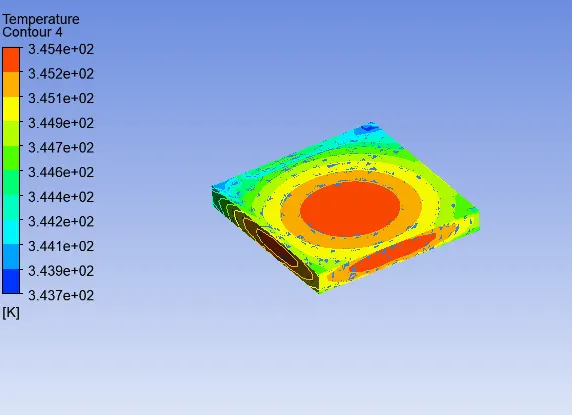
Temperature contour on processor
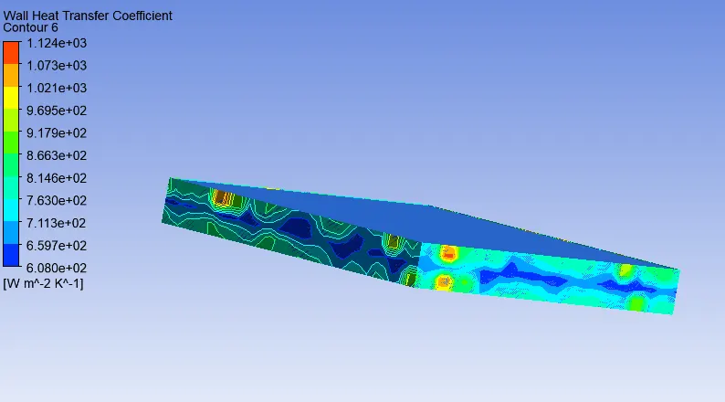
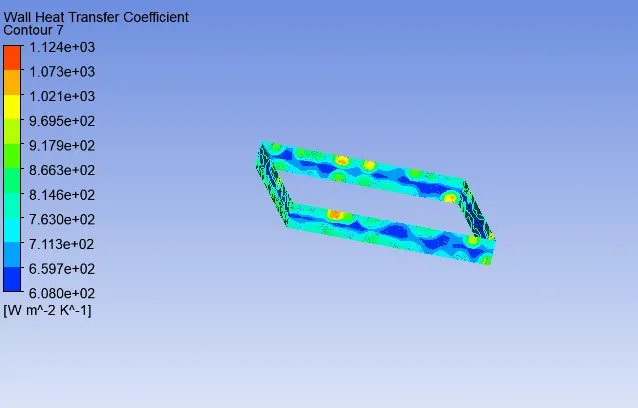
Wall heat transfer coeffecient attained by processor
CONCLUSION
- The CHT analysis on graphics card was conducted using ansys fluent. Steady state simulation was performed with both baseline mesh and refined mesh. For refined mesh the simulation was ran by varying the inlet velocities from 1m/s to 5m/s.
- The temperature distribution is finer in the refined mesh. Refined mesh produces more accurate results compared to coarse mesh.
- The potential hotspot on the model is the processor where the heat is generated.
- As the fluid velocity increases the convection rate increases. The maximum temperature on the processor at 1m/s fluid velocity is 420K and at 5m/s is 345K.
- Maximum temperature attained by the processor = 420K
- Maximum heat transfer coefficient attained by the processor = `1.124e+03 W/(m^2K)`