Week-6 Challenge: EV Drivetrain
1. Which types of power converter circuits are employed in electric and hybrid electric vehicle?
Ans :-
There are three types of Power converter circuits are used in electric vehicles.
- DC-AC Power converter
- DC-DC Power converter
- AC-DC Power converter
- DC-AC Power converter :-
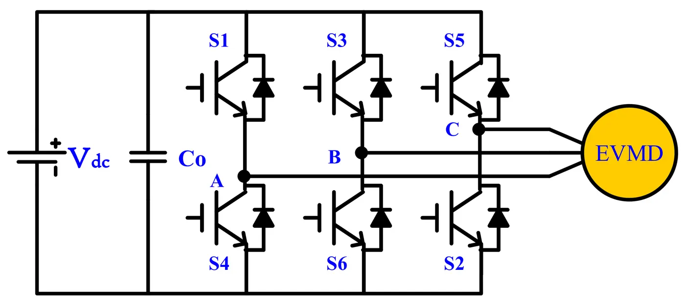
A DC- AC converter is basically use to convert Dc current into AC current to drive the 3 phase motor of electric and hybrid electric vehicle. This type of converter is not a converter its a inverter. A DC-AC power inverter converts a DC input voltage to the required magnitude and frequency of AC output voltage.In the battery (HEV/EV), the stored energy must be converted from DC to AC to drive AC motors using DC-AC converters. These converters are called traction inverters, which usually transfer power in the range of tens of kilowatts up to 50 kW. Usually, the semiconductor power switches used in these inverter topologies are insulated gate bipolar transistors (IGBTs). The typical voltage level for these power switches is 600–1200 V. Considering the high-power levels and voltage levels, a three-phase full-bridge inverter uses six semiconductor power devices to create the required voltage for driving electrical motors.
- DC-DC Power converter :-
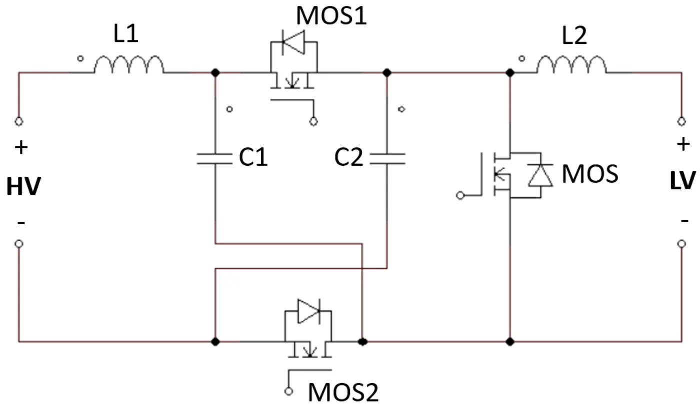
A DC-DC converter are generally used in EV and HEV to drive auxiliary parts like head lights, AC, music system, wiper and other auxiliary electrical items of an EV and HEV. The DC-DC converters the high voltage dc to low voltage ex- 48v to 12v. such type of converter are step down converter, and same DC-DC conveter makes low voltage to high voltage which is called Step-Up converter. The hardware and semiconductor are same in this converter like MOSFET, IGBT, only the control techniqe quit different.
- AC-DC Power converter :-
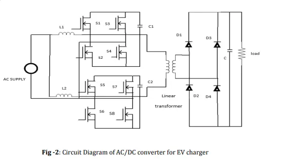
This converter is used to charge the battery of a EV. In this converter the AC voltage is converted into DC with the help of a full bridge Rectifier and this DC voltage again going to a DC-DC converter which provide the required voltage and current to the battery of EV. In EV battery charger both AC-DC, DC-DC converter works together. In this converter also we use MOSFET's and BJT.
Basically this type of converter is used in EV battery charger.
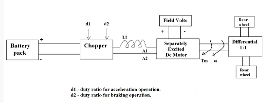
2. An Electric Vehicle's powertrain with 72V battery pack in shown in the diagram below. The duty ratio for acceleration operation is 'd1' and for the braking operation the duty ratio is 'd2'.
Solution:-
Steady state:-
Steady State Stability: Equilibrium speed of motor-load system can be obtained when motor torque equals the load torque. Electric drive system will operate in steady state at this speed, provided it is the speed of stable state equilibrium.
As per above defination Motor torque = Vehicle Torque is the steady state in EV drive.
The other parameters of the electric vehicle is given below,
Motor and Controller Parameters:
Rated Armature voltage= 72 V
Rated armature current= 400 A
Ra= 0.5Ω, KΦ= 0.7 Volt second
Chopper Switching frequency= 400 Hz
The vehicle speed-torque characteristics are given by the below equation

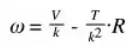
Now we find the motor torque characterstic by equation
So,
Given Duty Cycle 70% for supplied voltage
72 * 70%
= 50.4
So,
T = k/R * [V - k * ω]
Substituting all given values in above eq. we get
T = 0.7/0.5 * (50.4 - 0.7 * ω)
= 1.4(50.4 - 0.7ω)
T = 70.56 - 0.98ω Eq----------- (1)
Tv = 24.7 + 0.0051 Eq ------------ (2) Given,
At the steady State T = Tv
70.56 - 0.98ω = 24.7 + 0.0051
After solving above equation we get,
ω = 38.91 and ω = -231.071
So, in case of motor running with vehicle we consider positive speed.
so, ω = 38.91 rad/s Or 371 rpm.
Hence, steady state speed is 371 rpm.
3. Develop a mathematical model of a DC Motor for the below equation using Simulink.

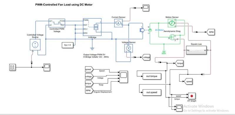
Summary:-
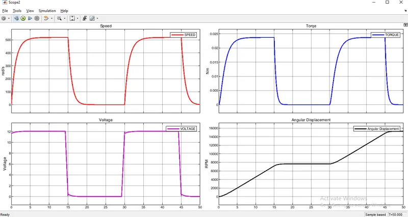
- Created a PWM input controlled fan model as shown in picture with using necessary blocks.
- We give the input to through the H-Bridge using the PWM signal.
- Fan motor is 12V 10watt power.
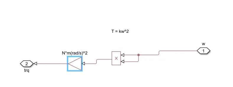
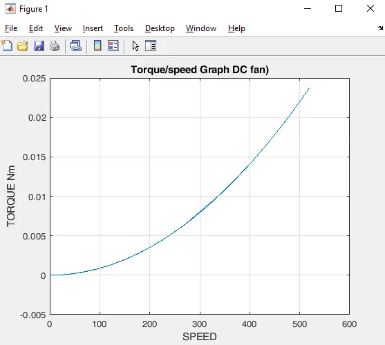
- We created a load to motor with used the eq. T=k*w^2. in sqare law sub system.
- Plot the output in scope.
Working:-
In this model we give the pulse signal to voltage soure and this voltage goes into the PWM voltage controller which controll and drive the H-Bridge output and H-Bridge drive the motor.
Here we used two block 'voltage sensor' and 'current sensor' to monitor the voltage and current supplied to the motor.
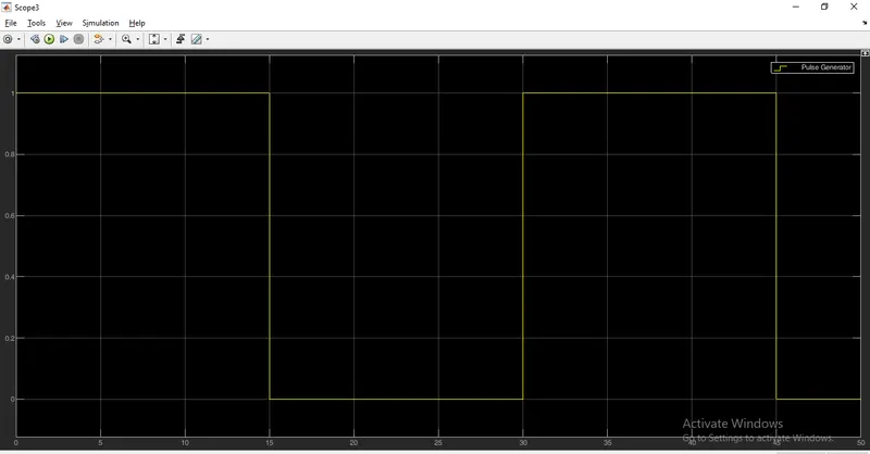
Input Pulse signal
50% duty cycle and 30 period(sec)
Square Law Subsystem
Output Results
Torque, Speed, RPM, Voltage
XY Plote Torque/Speed
4. Refer to the blog on below topic:
Induction Versus DC brushless motors by Wally Rippel, Tesla
Explain in brief about author’s perspective.
Ans:-
Introduction of author:-
Wally E. Rippel is a long-time developer and advocate of battery electric vehicles. Wally has a prominent role, labeled as himself, "Research Engineer, AeroVironment," In 1968, as an undergraduate student, he built the Caltech electric car (a converted 1958 VW microbus) and won the Great Transcontinental Electric Car Race against MIT.
In this artical "Induction Versus DC brushless motors" the author is talking about engine of vehicles and told about there differences. He said the engines are not same of all vehicles, all have some differences whether it is gas engine or electric.
The author brief the differences of electric vehicle, like change in battery, types of motor, types of motor controller. He said in the future there is two types of motor is compete each other and we cann't tell which one is better for electric vehicle.
The author explained about Dc Brushless motor and 3 phase Induction motor and try to make conclude which motor is good for vehicle drives but finally no one is winner and both motor are being used on the basis or their requirement and quality.