Week - 4
1.
- Implement control logic of a “washing machine” using Stateflow as per given sequence:
- If the power supply is available, the system gets activated
- If the Water supply is not available, stop the process & indicate through LED
- Soaking time should be 200s followed by Washing time of 100s.
- Then rinsing happens for next 20s & dryer runs for 50
After all the processes have completed turn on the finished LED
Description:-
The control logic of washing machine as per given sequence are as follows:-
To make a model for control logic of washing machine in stateflow chart pls follow the below steps.
- Open the simulink and create new model.
- Double click for instant search block and type chart to find chart block from stateflow library.
Blocks used in model:-
- Chart block
- constant block
- slider switch block
- lamp block
- Display block
Model:-
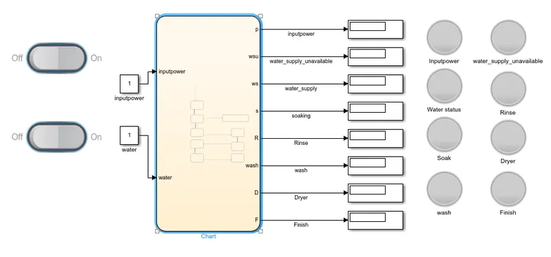
Chart prepared acoording to given conditions:-
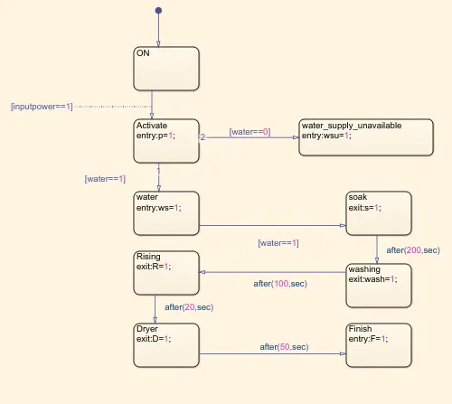
In this model the stateflow chart shows the following states:-
1. On :- This state activate when system is ON
2. Activate :- This state shows system activate when input power is on.
3. Water:- This state activate when water supply is available.
4. Soak:- This state activate after water supply available.
5. Washing:- This state activate after soaking according to given condition of after 200 sec.
5. Rinsing:- This state activate after washing at given condition of 100 sec.
6. Dryer:- This system activate after rinsing at given condition of 20 sec.
7. Finish:- This system is activate after rinsing at given condition of 50 sec.
Working of model and outputs:-
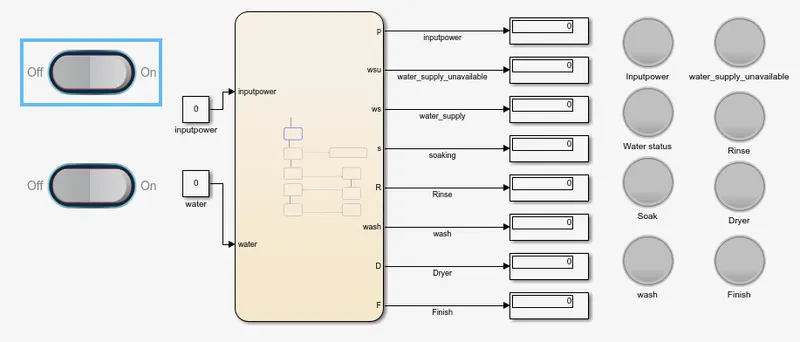
When input power switch is off position and value of switch is 0 then no state will activate.
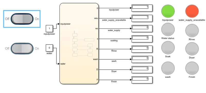
when input power switch is on and water supply is off then input power lamp indicate green signal and water_supply_unvailable lamp indicate red signal.
When water supply switch on and value is 1 and input power switch is on and value is 1 then all states will works according to given condition and shows all lamp green after completion of each step. And water supply unvailable lamp get deactivated, it indicates red color only when water supply is not available.
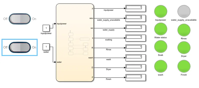
Hence, the model is working according to given condition.
2. Aim:-
Make a Simulink chart for the “Gear shift” logic as per below conditions:
Speed Range(kmph) Gear
0 to 15 1
16 to 25 2
26 to 40 3
41 to 60 4
Above 61 5
Give speed input while the simulation is running & display the gear number.
Description:-
To make a model of gear shift logic according to given conditions are we used following blocks are:-
- constant block
- variable gain block
- chart block
- Display block
- Lamp block
Model:-
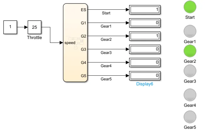
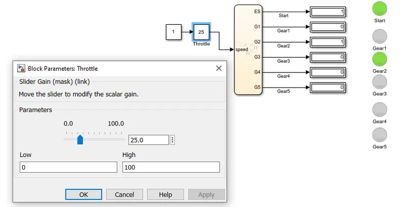
Chart:-
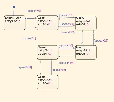
Model Working:-
After complete the model we run the model for infinite time meanwhile we change the value in slider gain to check the output according to given condition.
Hence,
The model is working correctly and justified the given condition.