Project
1. Aim:- Study and analys the BAJA All Terrain vehicle (ATV) simulink model and compare all.
Objectives:-
- To prepare a technical report explaining the functions of the sub-systems and blocks used used for preparing the model.
- Explain in detail the defference between all models.
- Understand the models working and comment on results.
Types Of Models:-
- BAJA ATV Model without dashboard (CVTmodel)
- BAJA ATV Model Data Extraction (CVTmodel_data)
- BAJA ATV Model with dasboard (CVTmodel_dashboard)
- BAJA ATV Model mapped lookup table without dashboard (CVTmodel_mapped)
- BAJA ATV Model mapped lookup table with dashboard (CVTmodel_dashboard_mapped)
Introducton:-
BAHA ATV
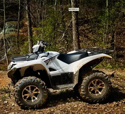
An all-terrain vehicle (ATV) is defined as a motorized off-highway vehicle designed to travel on four low-pressure or non-pneumatic tires, having a seat designed to be straddled by the operator and handlebars for steering control. ATVs are subdivided into two types as designated by the manufacturer. Type I ATVs are intended by the manufacturer for use by a single operator and no passenger.
BAJA SAE :-
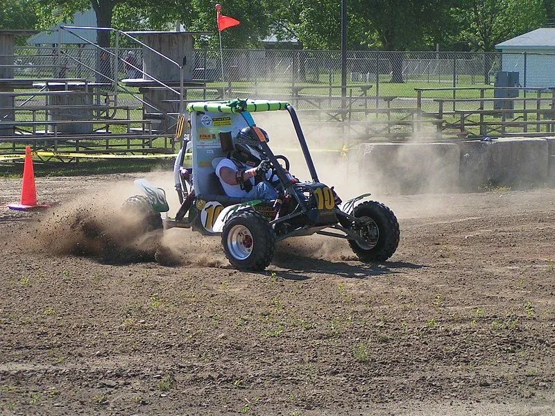
Baja SAE is an collegiate design series competition run by the Society of Automotive Engineers International (SAE International). Teams of students from universities all over the world design and build small off-road cars. The cars all have engines of the same specifications. As of 2018 the engine has been an unmodified Briggs & Stratton Model 19 Vanguard engine single-cylinder with a displacement of 305cc and power output of approximately 10 bhp (7.5 kW).
The goal in Baja SAE racing is to design, build and race off-road vehicles that can withstand the harshest elements of rough terrain. The vehicles used in Baja SAE racing are often similar in appearance to dune buggies. Before 2007, the events were called "Mini Baja."
1. BAJA ATV Model without Dashboard :-
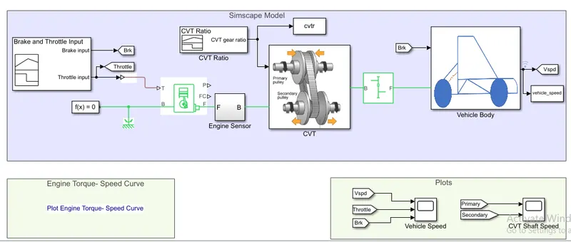
Blocks are Used In BAHA ATV Model:-
CVT (Continues Variable System)
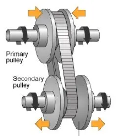
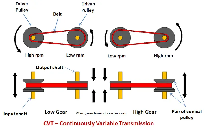
A continuously variable transmission (CVT) is an automatic transmission that can change seamlessly through a continuous range of gear ratios. This contrasts with other transmissions that provide a limited number of gear ratios in fixed steps. The flexibility of a CVT with suitable control may allow the engine to operate at a constant RPM while the vehicle moves at varying speeds.
Generic Engine Block:-
Represents a system-level model of spark-ignition and diesel engines suitable for use at initial stages of modeling when only the basic parameters are available. Optional idle speed and red line controllers are included.
The throttle input signal T lies between zero and one and specifies the torque demanded from the engine as a fraction of the maximum possible torque. If the engine speed falls below the Stall speed, the engine torque is blended to zero. If the engine speed exceeds the Maximum speed, the simulation stops and issues an error message.
Connections F and B are mechanical rotational conserving ports associated with the engine crankshaft and engine block, respectively. Connections P and FC are physical signal output ports through which engine power and fuel consumption rate are reported.
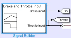
Signal Builder Block for Brake and Throttle Input:-
Signal Builder For CVT Ratio:-
Engine Sensor

Emgine sensor is a sub system of this model
Internal diagram of Engine sensor
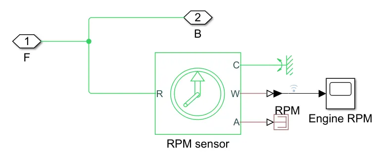
In this sub suystem a RPM sensor block is used to measure engine RPM.
Variable gear Block
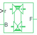
Vaiable ratio transmission Represents a variable ratio gearbox such as implemented by mechanical belt CVT, electric, or hydraulic transmissions. The physical signal input r defines the ratio of input to output angular shaft velocities.
Connections B (base) and F (follower) are mechanical rotational conserving ports. Specify the relation between base and follower rotation directions with the Output shaft rotates parameter.
Rotational Motion Sensor
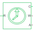
This block is used in CVT for primary and secondary RPM.
Inertia block

The block represents an ideal mechanical rotational inertia.
The block has one or two mechanical rotational conserving ports. The difference is purely graphical, as the ports are rigidly linked. The block positive direction is from its port to the reference point. This means that the inertia torque is positive if the inertia is accelerated in the positive direction.
Inertia block is used for Input and Output shaft.
PS Terminator Block:-
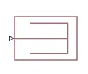
This block is used to terminate physical signal outputs. Unconnected physical signal output ports do not generate warnings, but connection to a PS Terminator can be used to indicate that the signal was not inadvertently left unconnected
Tire Magic Formula Block:-

Tyre magic formula block Represents the longitudinal behavior of a highway tire characterized by the tire Magic Formula. The block is built from Tire-Road Interaction (Magic Formula) and Simscape Foundation Library Wheel and Axle blocks. Optionally, the effects of tire inertia, stiffness, and damping can be included.
Connection A is the mechanical rotational conserving port for the wheel axle. Connection H is the mechanical translational conserving port for the wheel hub through which the thrust developed by the tire is applied to the vehicle. Connection N is a physical signal input port that applies the normal force acting on the tire. The force is considered positive if it acts downwards. Connection S is a physical signal output port that reports the tire slip. Optionally expose physical signal port M by setting Parameterize by to Physical signal Magic Formula coefficients. Physical signal port M accepts a four element vector corresponding to the B, C, D, and E Magic Formula coefficients.
Sinple gear block

Simple block Represents a fixed-ratio gear or gear box. No inertia or compliance is modeled in this block. You can optionally include gear meshing, backlash, and viscous bearing losses.
Connections B (base) and F (follower) are mechanical rotational conserving ports. Specify the relation between base and follower rotation directions with the Output shaft rotates parameter. Optionally include thermal effects and expose thermal conserving port H by setting Friction model to a temperature-dependent setting.
Earlier we studied about this block.
Vehicle Body
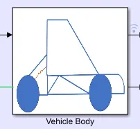
This block contain a sub system of a four wheel vehicle. shown i below image.
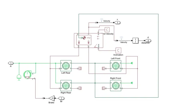
In sub system of this vehicle body we have different blocks used which details are:-
Main vehicle Body Block:-
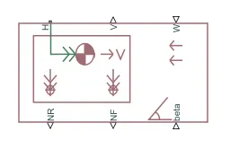
Vehicle body block represents a two-axle vehicle body in longitudinal motion. The block accounts for body mass, aerodynamic drag, road incline, and weight distribution between axles due to acceleration and road profile. The vehicle can have the same or a different number of wheels on each axle. Optionally include pitch and suspension dynamics or additional variable mass and inertia. The vehicle does not move vertically relative to the ground.
Connection H is the mechanical translational conserving port associated with the horizontal motion of the vehicle body. The resulting traction motion developed by tires should be connected to this port. Connections V, NF, and NR are physical signal output ports for vehicle velocity and front and rear normal wheel forces, respectively. Wheel forces are considered positive if acting downwards. Connections W and beta are physical signal input ports corresponding to headwind speed and road inclination angle, respectively. If variable mass is modeled, the physical signal input ports CG and M are exposed. CG accepts a two- element vector representing the x and y distance offsets from vehicle CG to additional load mass CG. M represents the additional mass. If both variable mass and pitch dynamics are included, the physical signal port J accepts the inertia of the additional mass about its own CG.
Double Shoe Brake block:-
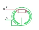
Double shoe brake block represents a brake arranged as two pivoted rigid shoes symmetrically installed inside or outside a drum and operated by one actuator. The actuator force causes the shoes to exert a friction torque on a shaft connected to the drum.
Connection S is a conserving rotational terminal associated with the drum shaft. Connection F is a physical signal port representing the force input to the actuator. Positive force creates friction torque that resists shaft rotation. Optionally include thermal effects and expose thermal conserving port H by setting Thermal port to Model.
Results :-
When we run model for 200 sec. and get the results
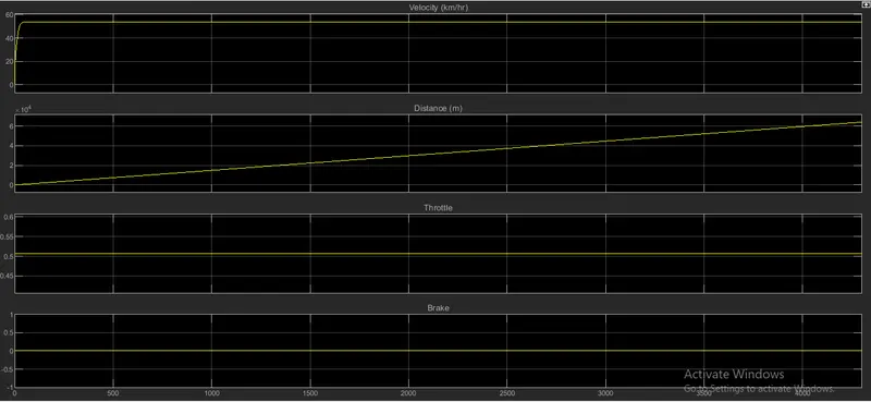
The input value of throttle is 0.5 and brake is 0
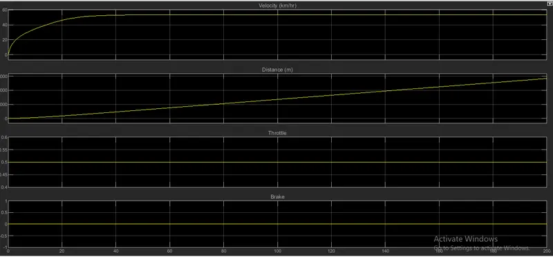
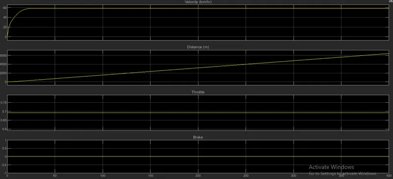
Above results shows when we applied throttle the velocity increase and constant after some time and distance continuously inscreasing.
CVT Results:-
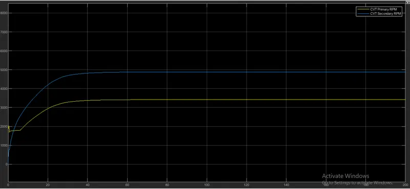
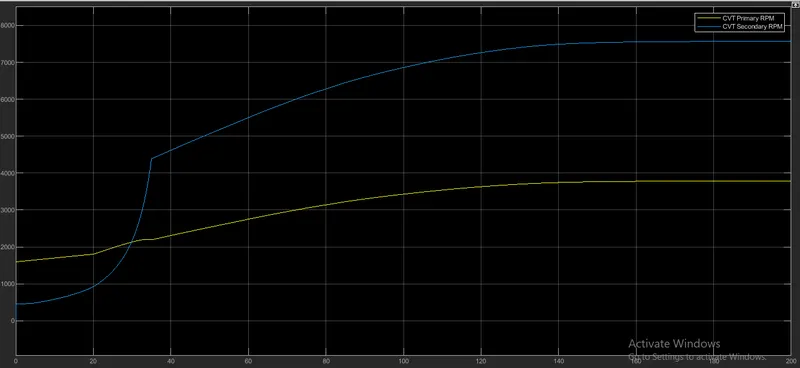
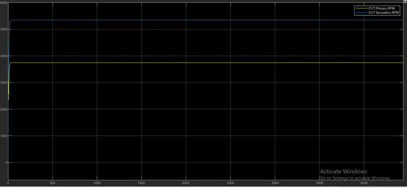
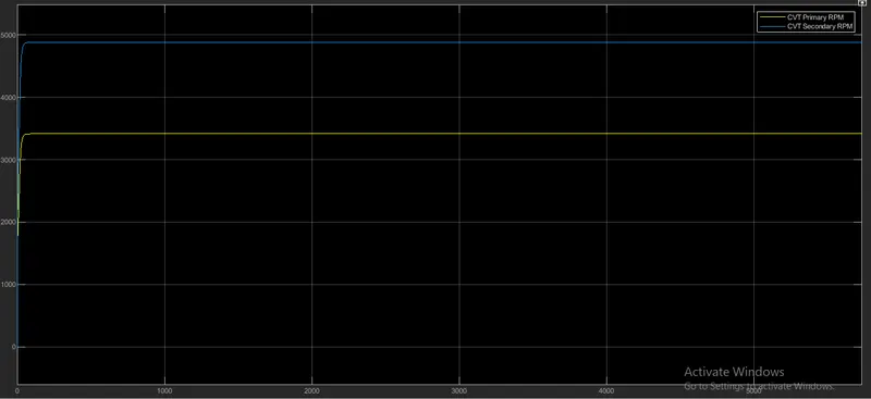
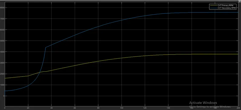
This is the RPM graph of primary and secondary pully of CVT. this results shows rpm increasing in initial stage and remain constant after reach full rpm
2. BAJA ATV Model Data Extraction:-
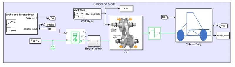
Description:-
The working principle of this model is same as previous model here we use only input data different.
Input Data
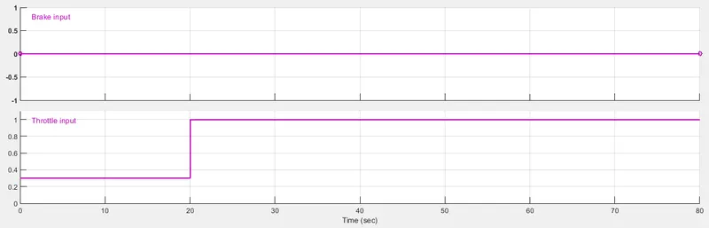
Throttle and brake Input:-
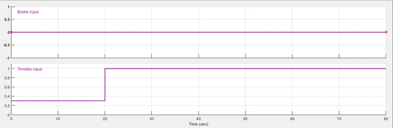
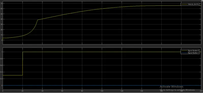
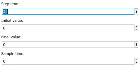
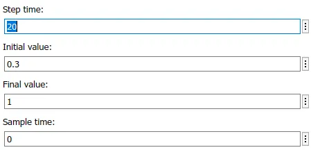
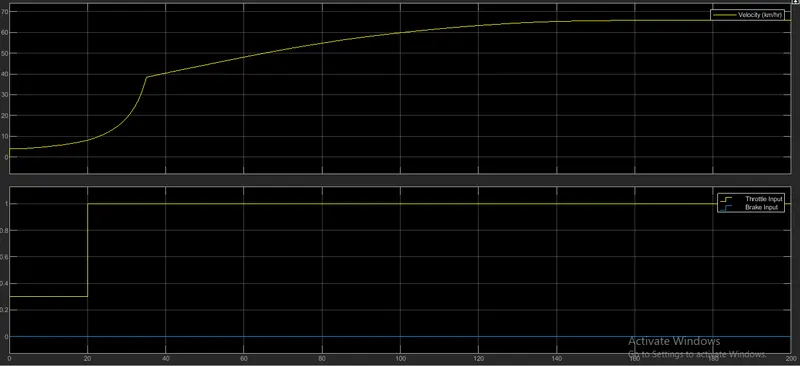
Here we provide brake value is 0 throttle value is 0.3 for 20sec and 1 after from 20 to 80 sec.
Results after run simulation run for 200 sec.
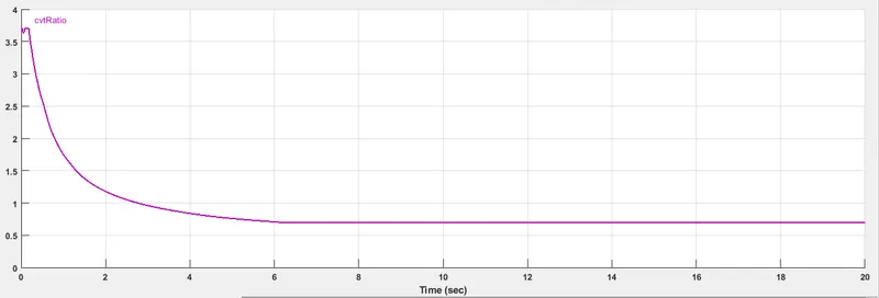
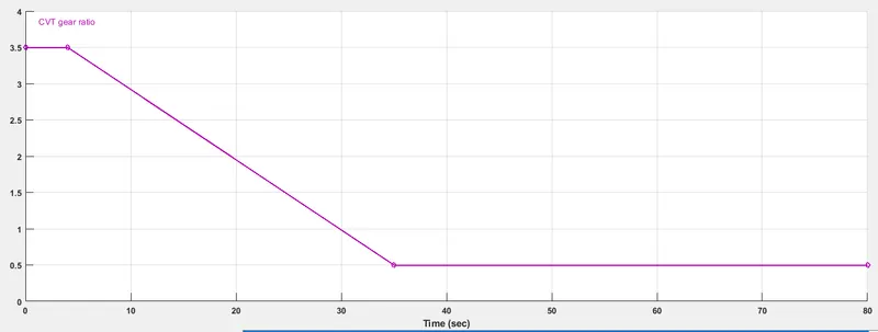
CVT Gear Ratio:-
CVT Shaft speed curve
Velocity and input signal result:-
3. BAJA ATV Model with dasboard:-
Description:-
In this model new things have added new but the working principle is same as previous model.
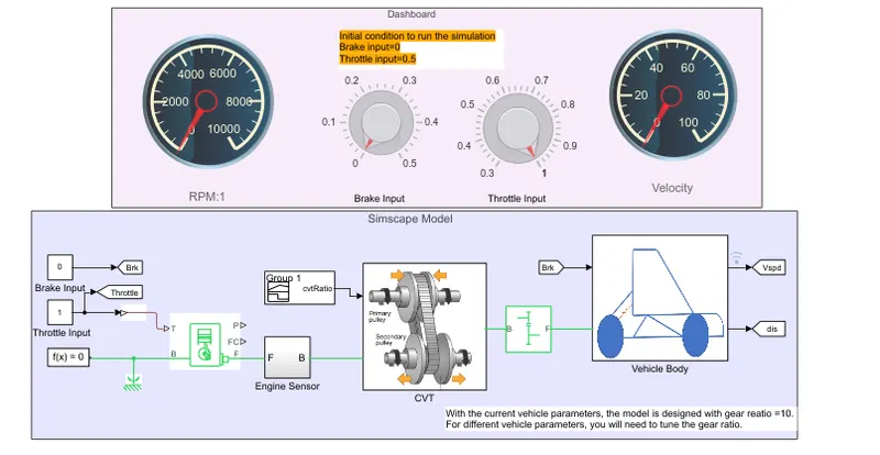
The only difference is that here a dashboard is added in model which shows in above model pic.
In this model the dashboard have two gauges one is for RPM and second is for velocity both shows the RPM and velocity on dashboard.
Another things have added in the dashboard is control knob for acceleartor and brake input. With the help of this knobs we adjust or apply brake and throttle direct from dashboard instead of to set paramater in model input block.
Rest all things are same in this same in this model.
Results:-
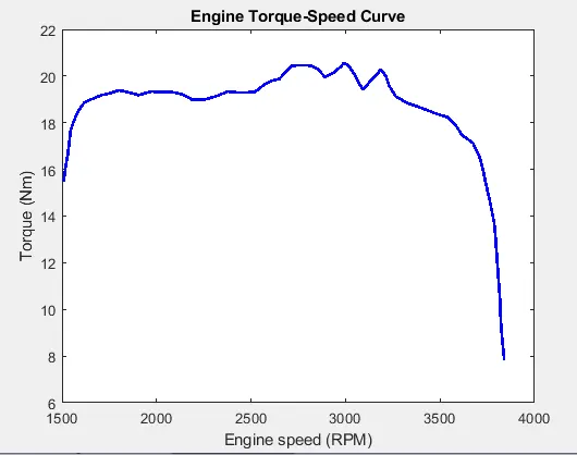
When throttle input value is 0.7
Engine Torque speed curve
Velocity,Distance, Throttle and Brake
CVT Shaft Speed
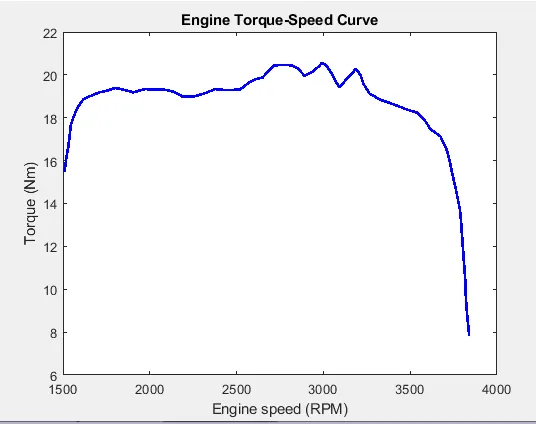
For throttle value 0.5
Engine Torque speed curve
CVT shaft RPP(Speed)
Velocity,Distance Throtle and Brake
4. BAJA ATV Model mapped lookup table
Description:-
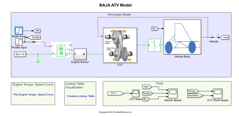
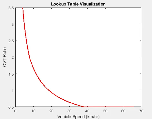
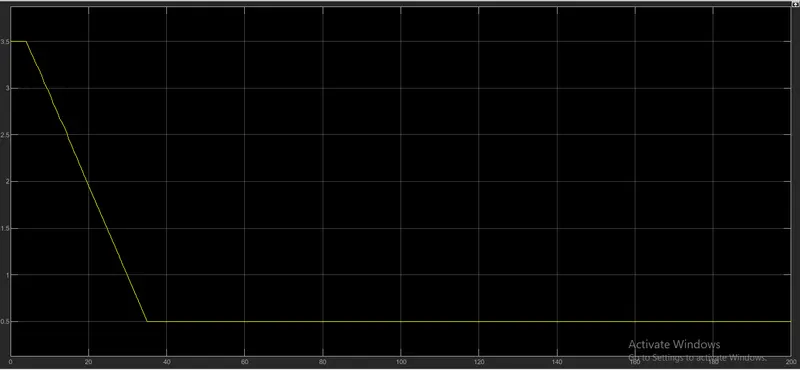
In this model the working priciple is same as previous models, but the diference is that the input is given by lookup table and CVT ratio is mapped with vehicle velocity.
Lookup Table visualize
Brake Input
Throttle Input
Results:-
CVT Shaft Speed
CVT Ratio
Vehicle speed and Throttle, Brake input
Conclusion:-
After study of all BAJA ATV model we find tha working principle is same of all models but the input are given in different way to each model so the results also vary as per input.