Week-6 Challenge: EV Drivetrain
HEV WEEK 6 CHALLENGE
QUESTION1:
POWERCONVERTERS USED IN ELECTRIC AND HYBRID ELECTRIC VEHICLE:
- Power converters are the devices used to convert and control the electrical power
- The controls achieved by ON &OFF operation of semiconductor switches(MOSFET,IGBT)
- The following are the types of powerconverters used in the EV system
1.AC-DC CONVERTER:
- This is the most common type of converter used in many application
- This converter used to convert the AC input voltage in to DC output voltage
- This converter also called as a rectifier circuit
- In EV,this converter mainly used to charge the battery from the input AC voltage grid or the charging station.
- This can be further classified as Half-wave ,Full-wave and bridge rectifier by the nature of output wave
- But mostly we use bridge rectifier to get continuous DC output voltage
- The below image represents a simple bridge rectifier circuit
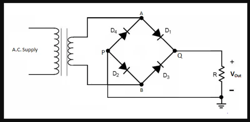
- The AC supply connected to a step-down transformer to reduce the input voltage to required rate
- This step down voltage is connected to a bridge rectifier containing four diodes (D1,D2,D3,D4)acting as switches
- The ouput of the rectifier circuit connected to the DC load or the Battery
2.DC-AC CONVERTER:
- This type of converter used to convert DC input voltage into AC ouput voltage
- In EV,it used to power the AC induction motor by the DC input battery power
- This converter also called as inverter
- The below image represents a simple DC-AC converter
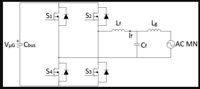
- The Input battery voltage is connected to four MOSFET (S1,S2,S3,S4)arranged in this manner
- Switching on S1 & S3,results in the postive flow of power from the battery to load
- Switching on S2,S4 results in the negative flow of power from battery to load
- Continuous cycle of this operation results in the AC output voltage which connected to AC motor
- Inductor and capacitor connected in the circuit act as filter circuit to achieve more sinusoidal nature in the output
3.DC-DC CONVERTER:
- This converter convert the dc input voltage to higher or lower dc ouput voltage.
- In EV,the main battery pack will have high power rating which designed to feed the motor
- But to run the auxiliary loads we have additional battery with lower power rating
- To charge this auxiliary battery ,we have to stpedown the main battery voltage to the required voltage rating
- This converter can be further classified as Buck and Boost converter
- Buck converter gives the lower dc output voltage and Boost converter gives the higher dc output
- In this application ,we are using a Buck converter to charge the auxiliary battery
- The below image represents a buck converter circuit
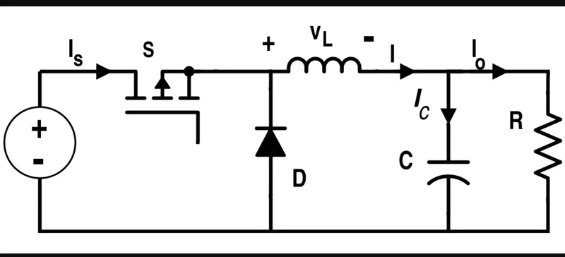
- In this circuit ,the battery connected in series with MOSFET parallel to a diode
- The reduction in the power done by switching operatons
- The below image represents a boost converter circuit
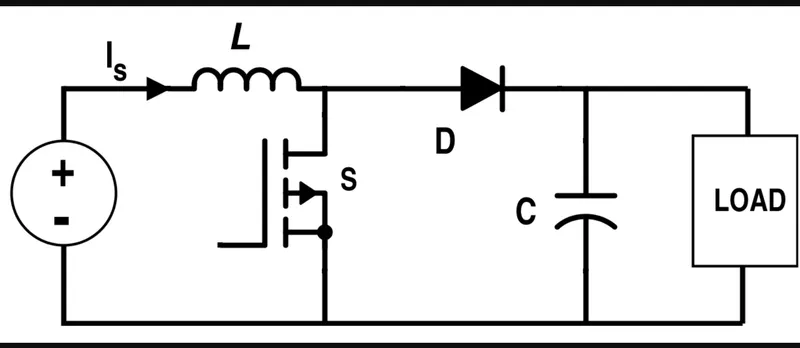
- In this circuit ,Input battery voltage connected parallel to Mosfet and in series with inductor and diode
- The power stored in the inductor will add up to the input voltage to provide high dc voltage level to load
QUESTION 2:
FINDING THE STEADY STATE SPEED OF THE GIVEN EV POWERTRAIN:
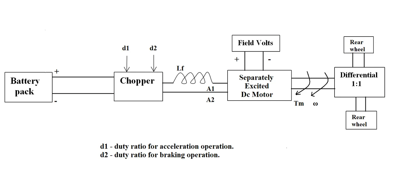
PARAMETERS:
- Battery voltage(Vs) - 72 V
- Armature resistance (Ra) - 0.5 ohms
- Armature current (Ia) - 400 A
- Motor constant (Km) - 0.7 V/s
- Switching frequency - 400 Hz
- Duty cycle - 70%
EQUATION:
- The torque-speed characteristic equation can be written as
T = (V*Km/Ra)-(Km^2*w/Ra)
- Where T-torque of the motor
- V- input voltage of motor
- Ra-armatur resistance
- Km-motor constant
- w-speed of the motor
SOLUTION:
- The given torque speed characteristics equation is
-
Tv = 24.7+(0.0051)*w^2 ----------(1)
- The duty cycle is 70%
- So the input voltage V for the motor can be calculated as
motor input voltage(V) = battery voltage (Vs)*duty cycle
V = 72*0.7
V = 50.4 V
- Substituting all known values in the torque-speed equation
T = (50.4*0.7/0.5)-((0.7^2)*w/0.5)
T = 70.56-0.98*w ----------(2)
- In steady state condition motor torque is equal to load torque
Tv=T
24.7+(0.0051)*w^2 = 70.56-0.98*w
- Simplifying the above equation we get
70.56-24.7-0.98*w = 0.0051*w^2
w^2+192.16*w-8992.16 = 0 --------(3)
- Equation 3 represents a first order differential equation
- Steady state speed can be determine by finding the root of this equation
- Roots of the equation determined in matlab workspace as
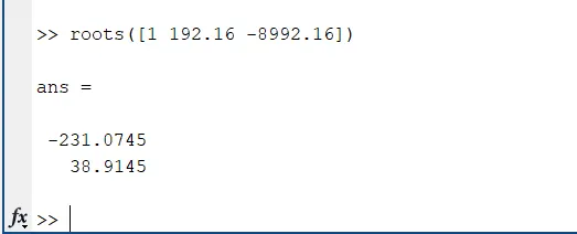
- As the vehicle moving in a steady state speed ,positive value of roots considered
- The steady state speed of the vehicle is
w = 38.9145 rad/s
- Converting it to rpm
w = 38.9145 *(60/2*pi)
w = 371.8 rpm
CONCLUSION:
- The steady state speed of the given vehicle powertrain for 70% duty cycle is 371.8 rpm
QUESTION 3:
MATHEMATICAL MODEL OF DC MOTOR:
SIMULINK MODEL:
REPORT:
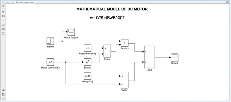
- The mathmatical model of DC motor designed using the below equation
w = (V/K)-(Ra/K^2) *T
- Where T-torque of the motor
- V- input voltage of motor
- Ra-armatur resistance
- K-motor constant
- w-speed of the motor
- A constant block with value 0.7 used to represent the motor constant K
- The motor voltage defined by another constant block with value 50.46
- These value divided by a divide block to get the term (V/K)
- Torque is represented as constant value 33 using a step block
- The resistancee value of 0.5 is defined in the constant block
- The resistance block divided by the square value of motor constant
- Multiplying torque and this divided value of resistance by square of motor constant using a product block to get the term
(Ra/K^2) *T
- The output of this product block subtracted by the terrm V/K to get the final equation
- The torque and speed is connected to scope blocks
- Run the model
- Outputs plotted in the scope block
RESULT:
- The speed output for the given torque value is plotted as shown below
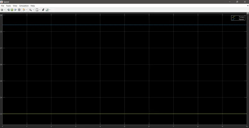
- In the graph ,yellow line indicates the value of torque
- And blue line indicates the corresponding speed of the motor
- For a torque value of 33 Nm ,speed obtained is 38.41 rad/s
CONCLUSION:
- The mathematical model of DC motor for the given equation is designed and the outputs verified
QUESTION 4:
Induction Versus DC brushless motors by Wally Rippel, Tesla
REPORT:
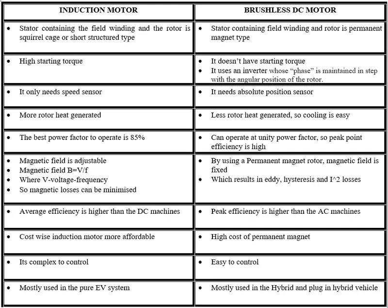
- In this blog ,author discussed about the difference between induction motors and brushless dc motor
- And their role in the future of electric vehicle
- Difference between both machines is briefly explained below
CONCLUSION:
- The perfect motor for an electric vehicle doesnt exists ,it depends on the application and personal requirement
- Still the induction and DC brushless motors will dominate the EV industry in the future