EV Drivetrain
Q1: Which types of power converter circuits are employed in electric and hybrid electric vehicle?
Q2: An Electric Vehicle's powertrain with 72V battery pack in shown in the diagram below. The duty ratio for acceleration operation is 'd1' and for the braking operation the duty ratio is 'd2'.
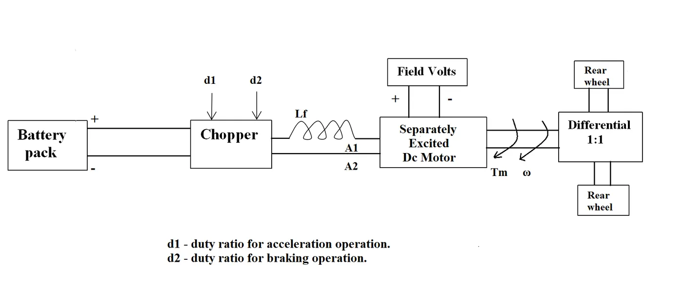
The other parameters of the electric vehicle is given below,
Motor and Controller Parameters:
Rated Armature voltage= 72 V
Rated armature current= 400 A
Ra= 0.5Ω, KΦ= 0.7 Volt second
Chopper Switching frequency= 400 Hz
The vehicle speed-torque characteristics are given by the below equation

What is EV steady state speed if duty cycle is 70%?
Q3: Refer to the blog on below topic: Induction Versus DC brushless motors by Wally Rippel, Tesla
Explain in brief about author’s perspective.
Aim: To study and explain about types of power converter circuits used in EV and HEV vehicles. To calculate the steady state speed from the given conditions and specifications of electric vehicle. To study about DC brushless motors vs Induction.
A1:
Theory:
AC: AC means Alternating Current. It is a type of electrical current, in which the direction of the flow of electrons switches back and forth at regular intervals or cycles.
AC is used for larger voltage such as voltage power lines, fans etc.
DC: DC means Direct Current. It is also known as unipolar current. It is electrical current which flows consistently in one direction.
DC is used for small voltages, such as speakers, mobile phones etc.
Power converter circuits: Power electronic technology deals with processing and controlling the flow of electrical energy in order to supply voltages and currents in a form that optimally suited for end user’s requirements. The circuits which are used for converting are known as Power converter circuits.
The power electronic circuit consists of both power part and control part. Power part transfers the energy from source to load and it consists of power electronic switches (SCR or TRIAC), transformers, electric choke, capacitors, fuses and sometimes resistors.
Depending on the type of function performed, power electronic converters are categorized into following types.
- AC to DC converter
- DC to AC converter
- DC to DC converter
- AC to AC converter
1. AC to DC converter: This converter is also known as rectifier. It converts AC supply from the main lines to DC supply for the load. This converter contains various components like transformer, switching unit, filter and control block. The transfroms adjusts the primary AC source supply to the input of rectifier stage. The rectifier converts the low voltage AC supply into DC supply. Rectifiers are majorly classified into two types. They are:
- Uncontrolled diode rectifiers
- Controlled rectifiers
2. DC to AC converters: This converter is also known as inverter. These converters are connected between DC source of fixed input, and variable AC load. Most commonly, these DC to AC converters are called as inverters. An inverter is a static device that converts fixed DC supply voltage to variable AC voltage. Here the fixed DC voltage is obtained from batteries or by DC link in most power electronic converter. The output of the inverter can be variable/ fixed AC voltage with variable/fixed frequency. These can be single phase or three phase inverter depending on the supply voltage. These converters are mainly divided into two groups.
- One is PWM based inverters and other multilevel inverters.
- Further, these are classified voltage source inverter and current source inverter. Each type is subdivided into different types such as PWM, SVPWM, etc.
- Multilevel inverters are more popular in industrial applications.
3. DC to DC converters: This converter is also known as chopper. Many DC operated applications need different levels of DC voltage from a fixed DC source. Some of these applications include subway cars, DC traction systems, control of large DC motors, battery operated vehicles, trolley buses, etc. They require variable DC to produce variable speed, so a power conversion device is needed. The output of the chopper can be less or greater than the input and also it can be fixed or variable. These can be unidirectional or bidirectional devices based on the application it is intended for. DC choppers are classified into three basic types based on input and output voltage levels. Theey are:
- Step-down or buck converter
- Step-up chopper or boost converter
- Buck or boost converter
4. AC to AC converters: This converter is also known as cycloconverter or matrix converter. AC to AC converters connect an AC source to AC loads by controlling amount of power supplied to the load. This converter converts the AC voltage at one level to the other by varying its magnitude as well as frequency of the supply voltage. These are used in different types of applications including uninterrupted power supplies, high power AC to AC transmission, adjustable speed drives, renewable energy conversion systems and aircraft converter systems. There are two types of converters. They are:
- AC to AC voltage converters
- AC to AC frequency converters
Usage of these converters in EV and HEV: These converters are used for various applications in EV and HEV vehicles.
The most of the converters used in EV and HEV are DC-AC and DC-DC converters. These converters are used in most of them applications. But AC-DC converter is used for only one application in these vehicles. AC-AC converter is not used in the vehicles. The applications of various converters used in EV and HEv are shown below.
| AC to DC converter | DC to AC converter | DC to DC converter |
| Charging the battery of vehicle from an external supply. The output is an AC and battery is DC. | Electric vehicle motor | Various onboard loads such as sensors, controls, entertainment, utility, and safety equipments. |
| Plays a significant role in capturing energy from regenerative braking and feeding it back to the battery. | Used in DC motor drives and electric traction. | |
| It accepts the high voltage from the traction battery and converts it typically in the three phase AC voltage suitable for the traction electric motor. |
Regenerative braking | |
| The inverter controls the amount of the energy generated by the motor and consequently the intensity of the braking. |
Backup power | |
| Battery charging |
A2:
Figure:
Given input parameters:
- Rated Armature voltage (Vbatt) = 72 V
- Rated armature current (Ia) = 400 A
- Armature resistance (Ra) = 0.5Ω
- KΦ= 0.7 Volt second
- Chopper Switching frequency= 400 Hz
- Duty cycle (d) = 70% = 0.7
- Torque speed characteristic is given as T = 24.7 + (0.0051 * ω^2) -------equation 1
We know steady state speed is ω. To find the steady state speed we need an equation for steady state speed.
V = Vbatt * d = 72 * 0.7
ω = (V/Kϕ) - ((T*R)/(Kϕ)^2)) ----------equation 2
Substituting the values in the equation 2.
ω = ((72 * 0.7)/0.7) - ((T * 0.5)/(0.7)^2)
ω = 72 - (0.5T/0.49)
72 - ω = 0.5T/0.49
0.49(72 - ω) = 0.5T
35.28 - 0.49ω = 0.5T
T = 70.56 - 0.98ω ----------equation 3
Substitute equation 1 in equation 3
24.7 + (0.0051 * ω^2) = 70.56 - 0.98ω
0.0051 * ω^2 + 0.98ω = 70.56 - 24.7
0.0051 * ω^2 + 0.98ω - 45.86 = 0
It is polynomial equation with second degree. By solving the factors for the equation 4, we get one positive and negative values as factors. ω = 38.915 and -231.072
Since the speed should be positive, therefore ω = 38.915 rad/s
Therefore, the steady state speed of EV if duty cycle 70% is 38.915 rad/s
A3:
Induction Versus DC brushless motors by Wally Rippel, Tesla
In this blog, the author, Wally Rippel explains how induction and DC brushless motor used now a days. He also explains in detail of both motors like advantages, requirements, etc. He explains these motors as following.
- Since we have various kinds of engines according to usage, prices and performance. In the same way electric drive vehicles also contain the same.
- Previously lead acid batteries, DC brush motors and contactor controllers are used. Now-a-days those were replaced and we use lithium batteries, DC brushless motors and moulating inverters. He states that technology is developing in each and every component or field.
- He starts with DC brushless motor. When the motor runs, it is necessary that the magnitude and polarity of the stator currents be continuously varied and the torque should be constant and electrical to mechanical conversion is optimally efficient. This can be done by the inverter and motors are useful without these.
- He later explains about induction motor which was invented by Nikola Tesla before 1889. Both motors contain same type of stators which contains three sets of distributed windings.
- The main difference between these two is rotor.
- Induction rotor doesn't have magnets just stacked steel laminations with buried peripheral conductors which forms a small in structure.
- The speed difference can be said. Since the current produced within the rotor is proportional to the voltage. The currents interacts with magnetic field and produces force.
- When induction motors are used, there is no need of inverters. Induction motors are directly compatible with conventional utility power, where, inverters are needed for DC brushless motors to develop torque. The phase is maintained in step with the angular position of the rotor.
- When operated from utility power, induction motors have limited starting torque and somewhat limited running peak torque capabilities.
- Variable speed also becomes possible simply by adjusting the inverter frequency. This shows that induction motors are competant with DC motors in applications.
- Since mostly all vehicles contain DC brushless motors now-a-days, only some vehicles like GM EV1 and tesla roadster etc uses induction motors.
- The differences between these two kinds are too small. Since the differences are in rotors and inverter controls. DC motors require absolute position sensor and induction requires speed sensor.
- The best power factor in induction is 85%. He also states the motor properties regarding eddy currents and hysteriesis.
- He states regarding permanent and ferromagnets used in EV's. Their cost and forces they gain in motors. Added development costs, but likely little or no recurring costs.
- Induction motors are difficult to control since laws are more and also achieving stability over the entire torque speed range is difficult.
He finally concludes that, both motors are used for EV's and almost gives same overall results. DC motors have more dominance in hybrid and plug-in hybrid vehicles. Where induction motors have dominance in pure EV. the technology develops more in future where induction can also be used in hybrid vehicles. Both motors should work side-by-side in future.
Conclusion:
- Types of power converter circuits and their application in EV and HEV are explained.
- The EV steady state speed for duty cycle 70% according to the given parameters can be 38.915 rad/s.
- The author perspection regarding induction vs DC brusless motor is they are almost same when compared overall. The usage of them and requirements are explained.
References:
https://core.ac.uk/download/pdf/192548695.pdf
https://www.electronicshub.org/4-different-power-electronic-converters/