Week-6 Challenge: EV Drivetrain
1. For a pure EV, the power sources have to be completely electrical (i.e batteries or supercapacitors or fuel cells).
For a hybrid EV, the power sources have to be a combination of IC engine and a battery.
Most electric and hybrid electric configurations use two energy storage devices:
i. one with high energy storage capability called the "main energy system" (MES), which provides extended driving range.
ii. one with high power capability and reversibility called the "rechargeable energy storage system" (RESS), which provides good acceleration and regenerative braking.
Energy storage or supply devices need to vary their output voltage with the load or state of charge. This is where the DC-DC converters come into play. These converters are used to interface the elements in the electric power train by boosting or chopping the voltage levels by storing the input energy temporarily and then releasing that energy to the output at a different voltage.
Generally, in EVs, the main energy source is assisted by one or more energy storage devices. In doing so, the system cost, mass and volume can be decreased and a significantly better performance can be obtained. A fuel cell/battery/supercapacitors hybrid provides the longest life time of the batteries. Use of high power DC/DC converters is necessary for EV power supply system. The power of the DC/DC converter depends on the characteristics of the vehicle such as top speed, acceleration time from 0 to 100 Km/h, weight, maximum torque, and power profile (peak power, continuous power). Generally, for passenger cars, the power of the converter is more than 20 KW and it can go up to 100 KW.
DC-DC Converters used:
In electric engineering, a DC to DC converter is a category of power converters and it is an electric circuit which converts a source of direct current (DC) from one voltage level to another, by storing the input energy temporarily and then releasing that energy to the output at a different voltage. The storage may be in either magnetic field storage components (inductors, transformers) or electric field storage components (capacitors). Generally a DC-DC converter is unidirectional, but it can be made bi-directional which is useful in applications requiring regenerative braking.
i. Non-isolated converters:
The non-isolated converters type is generally used where the voltage needs to be stepped up or down by a relatively small ratio (less than 4:1). And when there is no problem with the output and input having no dielectric isolation. There are five main types of converter in this non-isolated group, usually called the buck, boost, buck-boost, Cuk and charge-pump converters. The buck converter is used for voltage step-down, while the boost converter is used for voltage step-up. The buck-boost and Cuk converters can be used for either step-down or step-up. The charge-pump converter is used for either voltage step-up or voltage inversion, but only in relatively low power applications.
ii. Isolated Converters
Usually, in this type of converters a high frequency transformer is used. In the applications where the output needs to be completely isolated from the input, an isolated converter is necessary. There are many types of converters in this group such as Half-Bridge, Full-Bridge, Fly-back, Forward and Push-Pull DC/DC converters. All of these converters can be used as bi-directional converters and the ratio of stepping down or stepping up the voltage is high.
AC to DC Converters (Rectifier):
A rectifier is an electrical device that converts alternating current (AC), which periodically reverses direction, to direct current (DC), which flows in only one direction. This process is known as rectification.
Rectifiers may be vacuum tube diodes, wet chemical cells, mercury-arc valves, stacks of copper and selenium oxide plates, semiconductor diodes, silicon-controlled rectifiers and other silicon-based semi conductor switches.
Rectifiers are most often found serving as components of DC power supplies and high voltage direct-current power transmission systems.
DC to AC converter (Inverter):
A power inverter or inverter, is a power electronic device or circuitry that changes DC to AC. The input voltage, output voltage and frequency and overall power handling depend on the design of the specific device or circuitry. The inverter does not produce any power; the power is provided by the DC source. A power inverter can be entirely electronic or may be a combination of mechanical effects and electronic circuitry.
AC to AC converter:
A solid-state AC-to-AC converter converts an AC waveform to another AC waveform, where the voltage and frequency can be set arbitrarily.
2. Given,
Power from battery pack = 72V
=> Armature voltage = 72V
Given,
Armature current = 400A
Ra = 0.5Ω
Kφ = 0.7 V-s
Chopper switching frequency, ν = 400 Hz
Now, we know Torque-speed characteristics is given by the equation:
 ..............................(i)
And we are given Duty cycle = 70%
Hence, Actual voltage = Armature voltage x Kφ
= 72 x 0.7 V
= 50.4 V
We have speed equation of the motor as:
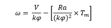
By simplifying the above speed, we obtain the torque as:
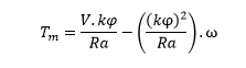
Substituting the values, we get
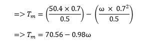 .....................(ii)
Equating equation (i) and (ii), we get
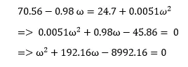
Solving this quadratic equation, we get,

Thus we have speed of the motor = 38.91 rad/s
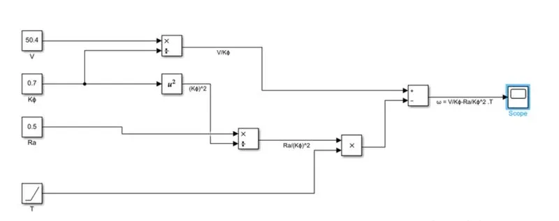
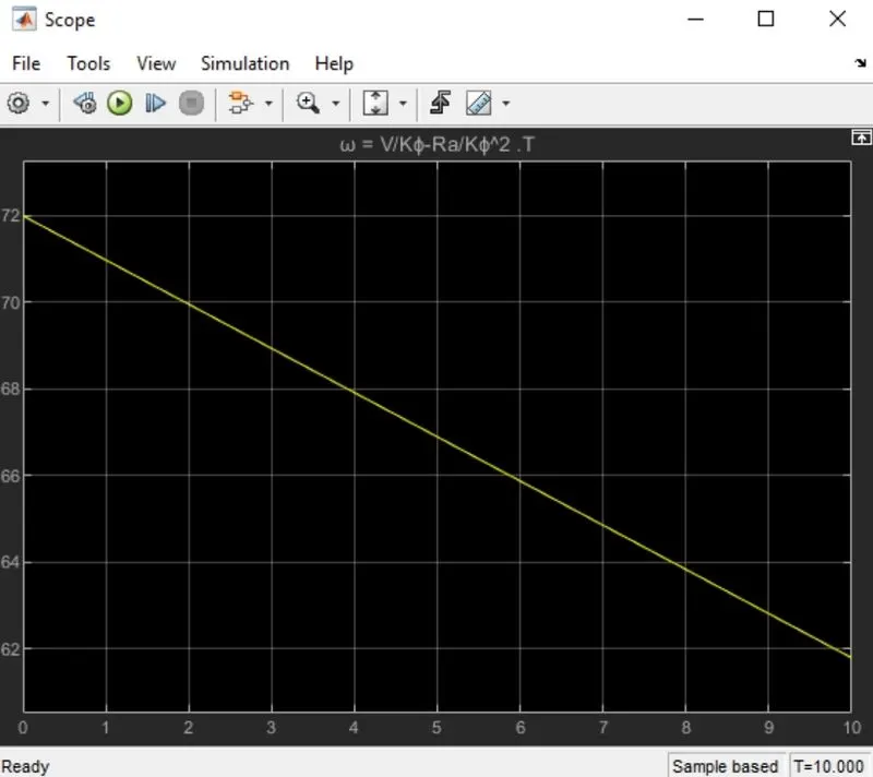
3. Considering the values as per the previous question, the mathematical model of the DC motor for the given equation is shown below:
4. There are many types of gas powered engines for example, flat heads, hemis, straights, opposed and V-configurations but we cannot select a particular one type of engine and call it the best because each of these types cater to different preferences. Similar is the case with electric vehicle drives.
What started off with Lead-acid batteries, DC brush motors and contactor controllers have now been replaced with Lithium ion batteries, DC brushless or induction motors and modulating inverters.
The key difference between BLDC and induction motors is with the rotor.
Brushless DC motors have a rotor which includes two or more permanent magnets that generate a DC magnetic field, which in turn enters the stator core and interacts with the current flowing within the windings to produce a torque interaction between the rotor and stator. The magnitude and polarity of the stator currents need to be continuously varied in such a way that the torque remains constant. This current control is provided by a device called an inverter.
In induction motors, the rotor has no magnets, only stacked steel laminations with buried peripheral conductors. Current flowing in the stator windings produce a rotating magnetic field that enters the rotor. The frequency of this magnetic field as experienced by the rotor is equal to the difference between applied electrical frequency and the rotational frequency of the motor. Accordingly, the voltage that is induced is also proportional to the speed difference between the rotor and electrical frequency. Similarly currents produced within the rotor conductor are also proportional to the speed difference. These currents interact with the original magnetic field to produce the required forces.
The direct compatibility of induction motors with conventional utility power is the main reason for their success. BLDC motors on the other hand need the use of an inverter whose phase is maintained in step with the angular position of the rotor.
CONS of Induction Motors:
3-phase induction motors only operates on AC current.
Shaft frequency is proportional to line frequency (generally equal to half of line frequency)
Limited starting torque when operated from utility power.
SOLUTIONS:
An inverter is required to power an induction motor from DC source.
Variable shaft speed can be achieved by adjusting the inverter frequency.
An feedback loop can be added to achieve exact frequency that the motor desires.
PRESENT STATE:
In the application of BLDC motors, the rotors generate much less heat and even the cooling is easier. BLDC motors have higher peak point efficiency and can operate at unity power factor (85% in case of induction drives). But, in order to achieve maximum efficiency from a BLDC motor, it is required to have an adjustable magnetic field but that is not possible.
Induction motors on the other hand can achieve adjustable magnetic field when they are equipped with a smart inverter. This can reduce the I^2.R losses along with eddy and hyserisis losses. Moreover, as the performance requirement increases, the machines become larger and the losses of a BLDC motor increases proportionately. But this is not the case with induction motors. Hence, for higher performance requirements, BLDC motors will definitely provide higher peak efficiency, but induction motors will provide higher average efficiency.
Also, permanent magnets are expensive and difficult to handle when ferromagnetic materials come close. So induction motors also have a cost advantage over BLDC motors.
Induction motors on the other hand are more difficult to control than BLDC motors, thus leading to increased development costs.
CONCLUSION:
We cannot decide at a clear winner among the two. But it can be said that induction motors will be more beneficial for high performance pure electrics whereas BLDC motors will continue to dominate the hybrid and plug-in hybrid market for some time now.