Week -2
1. Making a Simulink model of a doorbell using Solenoid Block
What is a Solenoid?
A solenoid is a device comprised of a coil of wire, the housing and a moveable plunger (armature). When an electrical current is introduced, a magnetic field forms around the coil which draws the plunger in. More simply, a solenoid converts electrical energy into mechanical work.
- The coil is made of many turns of tightly wound copper wire. When an electrical current flows through this wire, a strong magnetic field/flux is created.
- The housing, usually made of iron or steel, surrounds the coil concentrating the magnetic field generated by the coil.
- The plunger is attracted to the stop through the concentration of the magnetic field providing the mechanical force to do work.
Simulink Model:
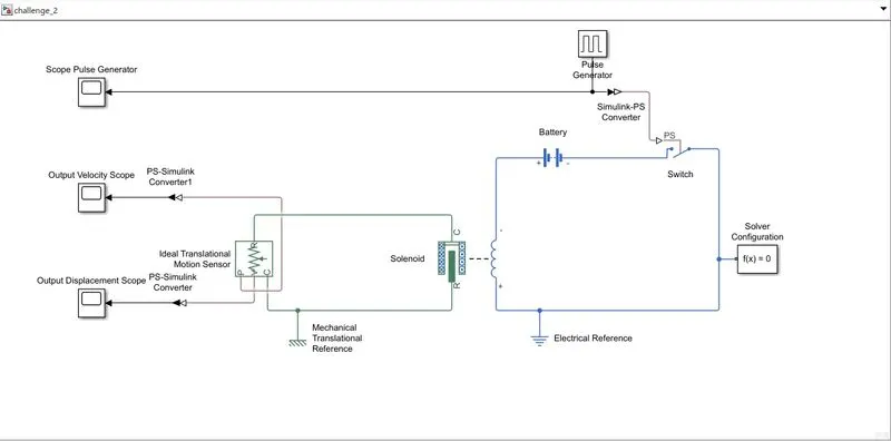
Blocks used:
i. Pulse Generator
ii. Simulink-PS Converter and PS-Simulink Converter
iii. Switch
iv. Battery
v. Solenoid
vi. Mechanical Translational Reference
vii. Electrical Reference
viii. Ideal Translational Motion Sensor
ix. Scope
Procedure:
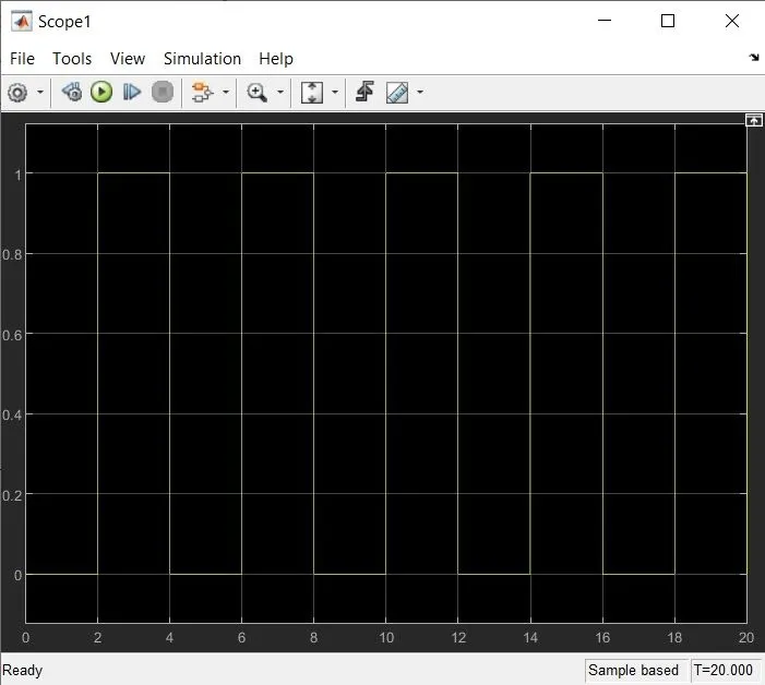
i. We use a Pulse generator block to provide us with the periodic input to the switch.
ii. The switch receives the input and connects and disconnects the circuit after a period of 2 seconds.
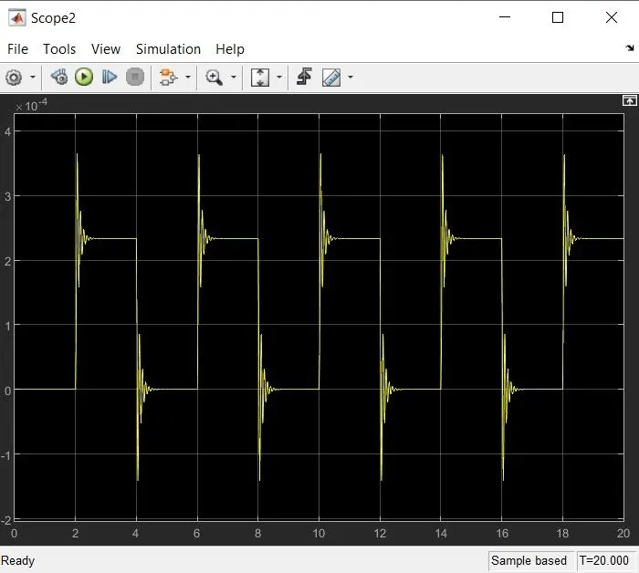
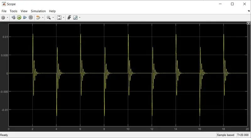
iii. When the switch is 'ON', current flows through the circuit. When current flows through the solenoid, the plunger moves. This movement is used to create a ringing sound in the doorbell.
iv. As a result the periodic 'ON/OFF' of the switch will cause the doorbell to ring.
Plots:
i. Pulse Generator input:
ii. Velocity output:
iii. Displacement output:
2. Use a thermistor to sense the temperature of a heater & turn on or turn off the fan as per the given conditions.
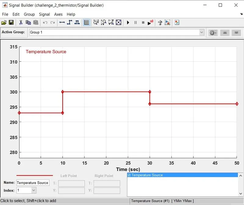
Temperature Source:
0-10s: 20 degC
10-30s: 27 degC
30-50s: 25 degC
Fan condition:
ON if temperature>25 degC; else OFF
For this we will use binary coding; 1 for ON and 0 for OFF.
What is a thermistor?
A thermistor is a semiconductor that has a resistance capacity more than that of a conducting material and less than that of an insulating material. Its electrical resistance varies with the change in the temperature or thermally sensitive resistor. There are mainly two types of thermistors, namely, Negative Temperature Coefficient (NTC) and Positive Temperature Coefficient (PTC).
a. A NTC thermistor will decrease its resistance value when temperature increases.
b. A PTC thermistor will increase its resistance value when temperature increases.
Procedure:
1. To create our model, we will the following basic blocks to start.
a. Thermistor
b. Signal builder
c. Controlled temperature source
d. Thermal reference
e. Battery
f. Voltage sensor
g. Resistor
h. Switch
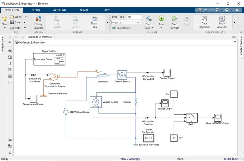
2. We first place a 'Thermistor' block and connect a 12V DC Voltage source across its terminals. We do this by connecting a 'DC voltage source' block and setting its voltage to 12 volts.
3. The temperature source to this thermistor will be provided by a 'Controlled Temperature Source' block. This Controlled Temperature Source block will receive signal from the Signal builder via the S port. The A port will be the reference. So the output from the Controlled Temperature Source will be the temperature difference between S and A.
4. The 'Signal Builder' block is used to create our temperature varying temperature signal w.r.t. time. We will have to convert the given temperatures from Celsius scale to Kelvin scale while creating our signal. The signal has to be sent to the Controlled Temperature Source block by using a Simulink-PS Converter block.
5. To measure the current in the thermistor circuit we connect a 'Current Sensor' block in series.
6. We add a 'Resistor' block in series and to measure the voltage across the resistor we connect a 'Voltage sensor' block in parallel with the resistor. The outputs of the Current sensor and Voltage sensor blocks are displayed using the 'Scope' block after passing them through PS-Simulink converter block that converts physical system values to Simulink values.
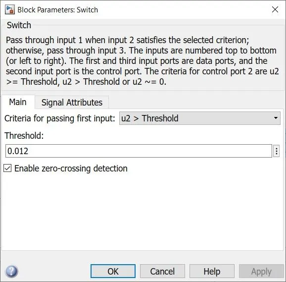
7. We finally need to add a 'Switch' block to our circuit that will implement the logic required to turn the fan ON or OFF. We will place the 'Switch' block and connect the output from the voltage source to the input 2 of the Switch. Input 1 will be be a constant 1 that is binary for ON and Input 3 will be 0 that is binary for OFF. The working of a Switch block is such that if Input 2 satisfies the threshold then it will pass Input 1 else it will pass Input 2. The output of the Switch block is connected to another Scope via PS-Simulink converter to view the Results.
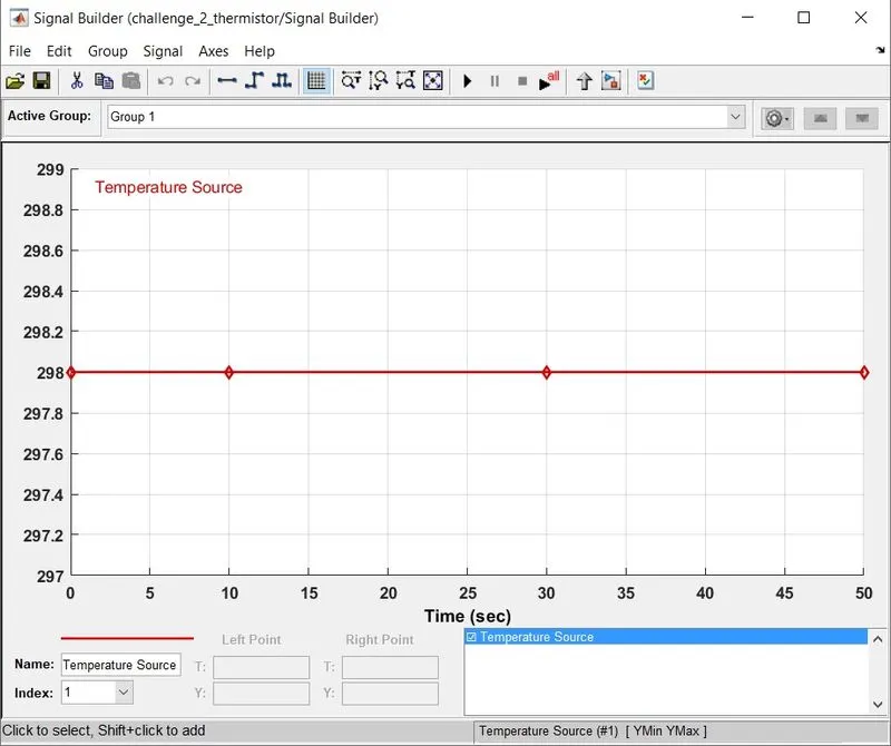
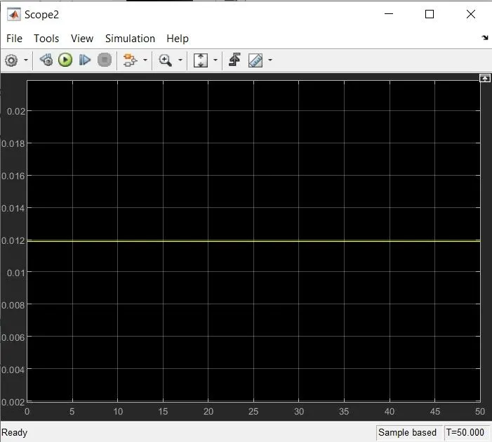
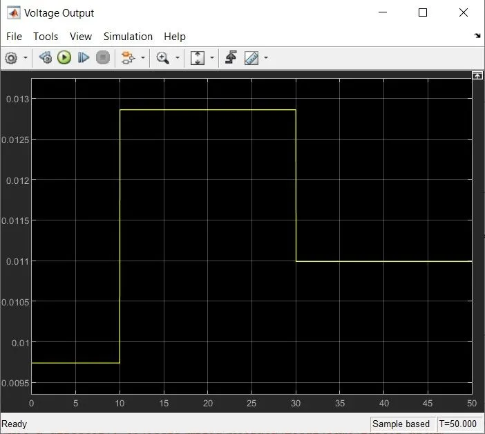
8. To first know our threshold value of voltage across the resistor, we set our signal builder to send a signal of 298 K (25 degC) and run the simulink. The voltage output we get (0.012 V) will be the our threshold value.
9. After setting our threshold value we then change the signal builder according to the given conditions and run the simulink again and record the output via the scope.
Simulink Model:
Obtaining our Threshold Value:
Setting Threshold Value:
Signal Input from Signal builder:
Voltage variation across the resistor:
RESULT (ON/OFF):
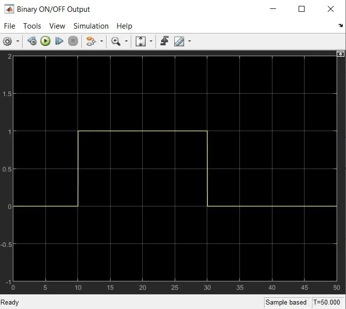
We can see that from 10 seconds to 30 seconds, the fan is switched on whereas for the rest of the time it is switched off.
References:
i. https://www.tlxtech.com/articles/solenoid-101-what-is-a-solenoid
ii. https://skill-lync.com/knowledgebase/thermistor-challenge