Week-6 Challenge: EV Drivetrain
EV BAtch-17
1. Which types of power converter circuits are employed in electric and hybrid electric vehicle?
ELECTRIC VECHICLE :
- An electric vehicle (EV) is a vehicle that uses one or more electric motors or traction motors for propulsion.
- An electric vehicle may be powered through a collector system by electricity from off-vehicle sources, or may be self-contained with a battery, solar panels, fuel cells or an electric generator to convert fuel to electricity.
HYBRID ELECTRIC VECHICLE :
- A hybrid electric vehicle (HEV) is a type of hybrid vehicles that combines a conventional internal combustion engine (ICE) system with an electric propulsion system.
- The presence of the electric powertrain is intended to achieve either botter fuel economy than a conventional vehicle or better performance.
- There is a variety of HEV types and the degree to which each function as an electric vehicle (EV) also varies.
- The most common form of HEV is the hybrid electric car, although hybrid electric trucks (pickups and tractors), buses boats and aircraft also exist .
POWER CONVERTOR CIRCUITS FOR ELECTRIC AND HYBRID ELECTRIC VECHICLE :
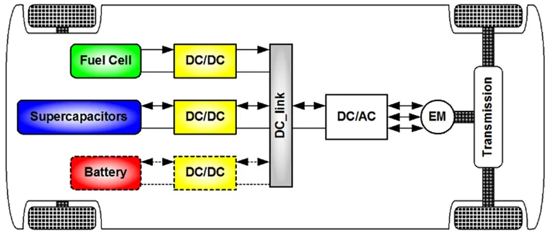
The different configurations of EV power supply show that at least one DC/DC converter is necessary to interface the FC, the Battery or the Supercapacitors module to the DC-link DC/DC converters can be designed to transfer power in only one direction from the input to the output. However, almost all DC/DC converter topologies can be made bi directional A bi-directional converter can move power in either direction, which is useful in applications requiring regenerative broking The most comman DC/DC converters can be grouped as follows:
Power electronic technology deals with processing and controlling the flow of electrical energy in order to supply voltages and currents in a form that optimally suited for end user’s requirements.
power electronic converter uses power electronic components such as SCRs, TRIACs, IGBTs, etc. to control and convert the electric power. The main aim of the converter is to produce conditioning power with respect to a certain application.
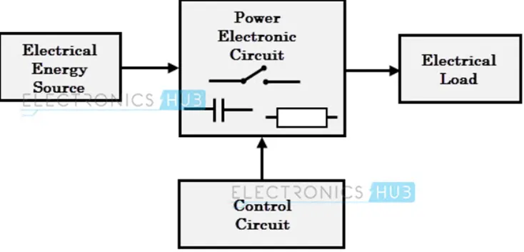
The block diagram of a power electronic converter is shown in figure above. It consist of an electrical energy source, power electronic circuit, a control circuit and an electric load. This converter changes one form of electrical energy to other form of electrical energy.
Power electronic technology deals with processing and controlling the flow of electrical energy in order to supply voltages and currents in a form that optimally suited for end user’s requirements.
The power electronic circuit consists of both power part and control part. Power part transfers the energy from source to load and it consists of power electronic switches (SCR or TRIAC), transformers, electric choke, capacitors, fuses and sometimes resistors.
Power electronic converters perform various basic power conversion functions. This converter is a single power conversion stage that can perform any of the functions in AC and DC power conversion systems.
Depending on the type of function performed, power electronic converters are categorized into following types.
There are 4 main categories of power converter circuits which are used in electric and hybrid electric vehicles.
They are listed and elaborated upon below:
AC to DC converter:
This type of converter takes an AC power supply and converts it to a DC one. Power generated from a power plant is transmitted to our homes at a voltage of 230V at a frequency of 50Hz which we can use to power our electrical appliances. But our appliance operates on a DC supply, not an AC one and so we need a converter for this application. Examples of Ac to DC converters are: phone charger, laptop charger etc.
An AC power supply has an alternating waveform which repeatedly reverses direction. An AC to DC converter will prevent the current changing direction, so that it only flows unidirectionally. In the circuit of an AC to DC converter, there is a step-down transformer, a diode, a capacitor and a low dropout voltage (LDO) regulator.
converter, there is a step-down transformer, a diode, a capacitor and a low dropout voltage (LDO) regulator. The step-down transformer takes the high level 230V from the mains supply and steps it down to a lower level or 13V for our use, but it is still in AC form.
Then, a diode or group of diodes is implemented to restrict the current to flow in just one direction. In an AC waveform, there will be positive and negative peaks at each half cycle like a sine wave. The diode(s) will remove the negative parts of the waveform so that there are positive peaks only. This is called 'rectifying' and this part of the circuit is referred to as a 'rectifier'. This can be a half wave, full wave or a bridge rectifier.
Then, the rectified output voltage waveform is smoothened by a filter capacitor. Finally, the LDO regulator will regulate the output for our use
In the case of EVs or HEVs, the battery pack which operates with a DC power supply is charged at home or at a charging station both of which are supplied power in AC form from the electric grid. So, the chargers for these vehicles are an example of the AC to DC power converter.
DC to AC converter
This type of converter takes a DC supply and converts it to an AC one. Power which is supplied from a battery or capacitor can have its form changed to the AC type for use in homes or systems which have an AC load.
This type of converter is referred as an 'inverter' and is widely used in homes and in EV/HEVs.
The DC supply is changed to an AC waveform using an electronic switch, which is basically a set of semiconductors transistors e.g. IGBTs, MOSFETs. These switches are controlled by a controller to either be in an open or closed position to direct the flow of current in a circuit. The controller sends signals to the switches to tell it to open/close, and even decides the frequency for the same. By doing this operation, the DC current mimics an AC current and can be fed to the load which requires it.
In the case of EVs and HEVs, the battery pack will supply its power to the inverter. The inverter contains a transformer which consists of a primary and secondary winding. The current from the battery is first supplied to the primary winding where the electronic switches will repeatedly reverse the direction of the current to create an AC waveform.
This current will return back the way it same from. The AC current in the primary winding will induce an AC current in the secondary winding which then supplies this current to an AC load e.g. the AC traction motor.
DC to DC converter
This type of converter is similar to a transformer in that it can change the voltage from its current level to another level. It can take an input supply of voltage and increase it or do the exact opposite and decrease it similar to a step up or step down transformer. This kind of a converter is called a 'chopper'. The purpose of using this type of converter is to provide the necessary level of power to a particular component and for the safety of the appliance and the user.
It works by taking the DC supply and passing it through a switching element which converts the waveform to a square wave which is actually AC in nature. Then this AC is passed through a filter which will will turn it back in to a DC supply for use in a load. In EVs, HEVs and conventional vehicles, this type of converter is used for various purposes.
There are 2 main types of DC to DC converters which are isolated and non-isolated type. The non-isolated type can be subdivided to 5 types:
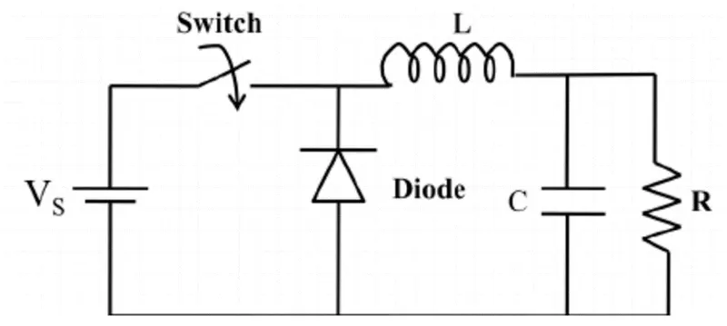
- Buck - to step down the voltage
- A buck converter (step-down convined) is a DC to DC power convertor which steps down voltage from s input(supply) tons output (load) it is a class of switched moge power supply [SMP Typicary containing at least two semiconductors a diode and a transistor, atuough modern buck.converters frequently replace ine diode with a second transistor used for synchronous rectification and at least one energy storage elament, o capacitor inductor or the two in combination.
- To reduce voltage ripp Tillers mod of capacitors (offers in combination with inductors are normally paded to such a convertel's output lood-sids filter) and imput (supply-sido filter)
- Boost - to step up the voltage
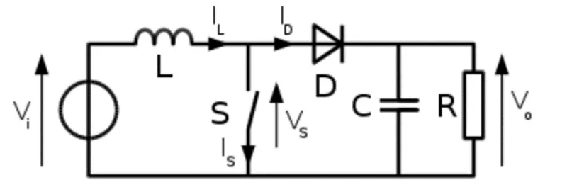
- A boost converter (step-up converter) is a DC to DC converter that steps up voltage from its input (supply) to its output (load).
- It is a class of switched mode power supply (SMPS) containing at least two semiconductors a diode and a transistor and at least one energy storage element: a capacitor inductor or the two in combination. To reduce voltage ripple, filters made of capacitors (sometimes in combination with inductors) are normally added to such a converter's output (load-side filter) and input (supply-side filter).
BUCK-BOOST :
- Buck-boost- The buck-boost converter is a type of DC to DC converter that has an output voltage magnitude that is either greater than or less than the input voltage magnitude. It is equivalent to a llyback converter using a single inductor instead of a transformer.
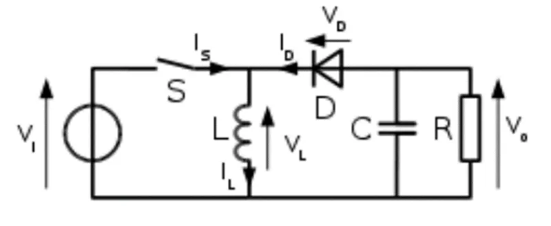
- Buck/Boost - this can do both step up and step-down operations but is mainly used to reverse polarity
- Cuk - similar to the Buck/Boost type
- Charge Pump - to step up/step down the voltage for low power sources.
-
The isolated type can be subdivided in to 2 types:
Flyback converter - similar to the Buck Boost converter except it uses a transformer instead of an inductor to store energy
Forward converter - this type will use a transformer to send energy between the input and output in a single step
AC to AC converter:
-
This type of converter takes an input AC waveform with a particular voltage and frequency and outputs a different AC waveform with another voltage and frequency. The output voltage and/or frequency can be changed or maintained depending on the application. This converter has many applications in our daily life e.g. lamp dimming, motor speed control.
-
There are 4 main types of AC to AC converters:
Cycloconverters
This type is also known as a frequency changer as it will change the frequency of an input AC waveform and output an AC waveform with another frequency but it can also change the magnitude of the power. This type of converter does not have any DC linkages and avoids any conversion between AC and DC to prevent losses and save costs. The input wave's frequency is changed by changing the firing angle applied to a thyristor. By switching the positive and negative limb thyristors, we can get an output waveform that has a stepped up/down frequency compared to the input.
AC to AC convert with DC Link
As the name suggests, this type includes a DC link along with a rectifier and an inverter. The input AC waveform is first rectified by the rectifier to remove the negative portions of the AC wave and output only the positive portions.
This creates a DC waveform which is then stored in the DC link and is then converted back to an AC waveform using the inverter.
This type converts from AC to AC directly without using a DC linkage to reduce costs and losses that would otherwise be incurred with a DC link storage element. It is used mainly to increase the reliability and efficiency of a system. Matrix converters use bidirectional switches (IGBTs) to conduct current and block voltages of both polarities.
Matrix Converter
- This type converts from AC to AC directly without using a DC linkage to reduce costs and losses that would otherwise be incurred with a DC link storage element. It is used mainly to increase the reliability and efficiency of a system. Matrix converters use bidirectional switches (IGBTs) to conduct current and block voltages of both polarities. This type converts from AC to AC directly without using a DC linkage to reduce costs and losses that would otherwise be incurred with a DC link storage element. It is used mainly to increase the reliability and efficiency of a system. Matrix converters use bidirectional switches (IGBTs) to conduct current and block voltages of both polarities.
-
Hybrid Matrix Converter
This type is very similar to the matrix converter in that they combine the AC/ /DC/AC design with the matrix design. It uses unidirectional switches and 2 converter stages, without the DC link to reduce the size and weight of the converter.
2. An Electric Vehicle's powertrain with 72V battery pack in shown in the diagram below. The duty ratio for acceleration operation is 'd1' and for the braking operation the duty ratio is 'd2'.
given data:
The other parameters of the electric vehicle is given below,
Motor and Controller Parameters:
Rated Armature voltage= 72 V
Rated armature current= 400 A
Ra= 0.5Ω, KΦ= 0.7 Volt second
Chopper Switching frequency= 400 Hz
The vehicle speed-torque characteristics are given by the below equation

What is EV steady state speed if duty cycle is 70%
As the torque formula is given, we need to find the speed in rad/ sec. Use the other expression available which is given
below:
Rated Armature voltage, VA = 72 V
Rated armature current= 400 A
Chopper Switching frequency= 400 Hz
Tv = 24.7 + (0.01152
For Duty Cycle, ∂ = 70%
Voltage = VA x∂
= 72 x 0.7
= 50.4 v
We know,
Torque,)
By Substituting the given values,
Torque, 
= 1.4 x (50.4 — 0.7 w)
= 70.56-0.98w
T =70..96-0.98w
Tv = 24.7 + (0.0115w2
At T = Tv;
70.56 - 0.98 w = 24.7 + 0.0051
or, 0.0051 + 0.98 w +24.7 -70.56 = O
or, 0.0051 + 0.98 - 45.86 = o
w = 38.915 or -231.072
Since Speed cannot be negative, we will consider that the EV steady-state speed, if the duty cycle is at 70%, is
w= 38.915 rad. S-1 or 371 rpm
As the torque formula is given, we need to find the speed in rad/ sec. Use the other expression available which is given
3 . Develop a mathematical model of a DC Motor for the below equation using Simulink.
ω= V/Kϕ-Ra/Kϕ^2 .T
AIM :
To Develop a mathematical model of a DC Motor for the below equation using Simulink.
ω= V/Kϕ-Ra/Kϕ^2 .T
DC MOTOR :
- A DC motor is any of a class of rotary electrical motors that converts direct current (DC) electrical energy into mechanical energy.
- The most common types rely on the forces produced by magnetic fields. Nearly all types of DC motors have some internal mechanism, either electromechanical or electronic, to periodically change the direction of current in part of the motor.
- DC motors were the first form of motor widely used, as they could be powered from existing direct-current lighting power distribution systems.
- A DC motor's speed can be controlled over a wide range, using either a variable supply voltage or by changing the strength of current in its field windings.
- Small DC motors are used in tools, toys, and appliances.
- The universal motor can operate on direct current but is a lightweight brushed motor used for portable power tools and appliances.
- Larger DC motors are currently used in propulsion of electric vehicles, elevator and hoists, and in drives for steel rolling mills.
- The advent of power electronics has made replacement of DC motors with AC motors possible in many applications.
SIMULATION BLOCKS :
- CONSTANT BLOCK
- RAMP BLOCK
- PRODUCT BLOCK
- SQUARE BLOCK
- ADD BLOCK
- SCOPE
SIMULATION MODEL :
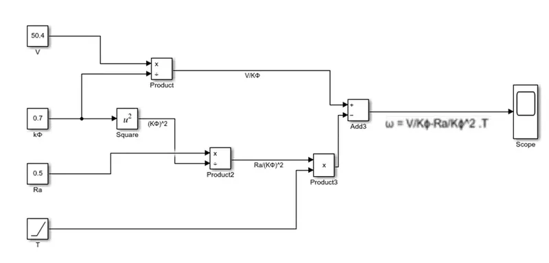
EXPLANATION :
- First open the matlab and click on the simulink then we get simulink blank model .
- Next go to the library and search the required blocks i.e, constant, ramp, product , add, scope, square .
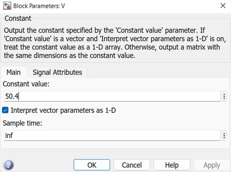
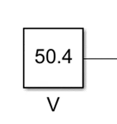
- Now change the constant value is 50.4 v let consider this constant as voltage .
- Then change value of another constant is 0.7 let consider this constant as kϕ.
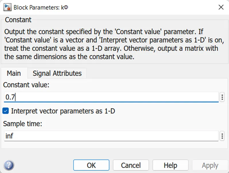
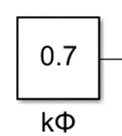
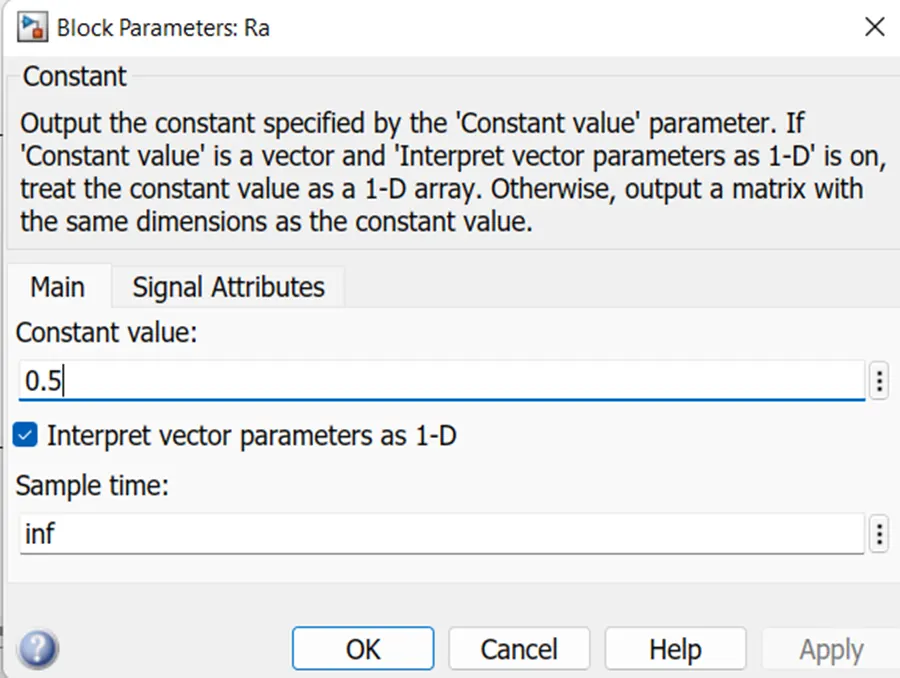
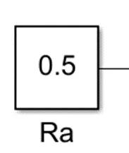
Now change the value of another constant is 0.5 let this constant consider as Ra
- connect the circuit as per the above figure . Now click on the run button after complete the compile we can check the results in the scope .
OUTPUT :
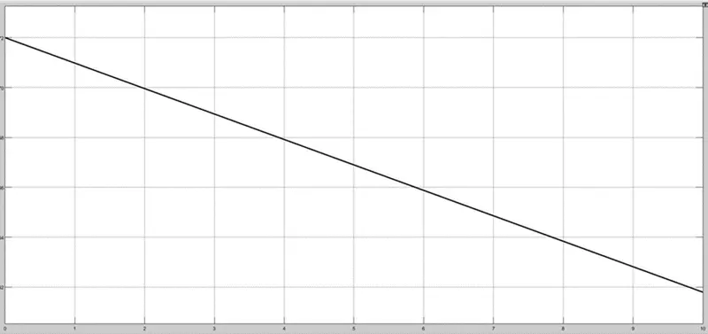
CONCLUSION :
The mathematical model of a DC motor by using given equation ω= V/Kϕ-Ra/Kϕ^2 .T is done .
4. Refer to the blog on below topic:
Induction Versus DC brushless motors by Wally Rippel, Tesla
Explain in brief about author’s perspective.
Objective: To brief about the blog written by an author from Tesla.
Main Points:
- There is no such thing called the best engine. According to the personal requirements, we need to adapt the enginetype.
- In the course of time, Lead-acid batteries are replaced by Lithium-ion batteries.
- In the course of time, DC brush motors are replaced by DC Brushless or Induction Motors.
- In the course of time, Contactor Controllers are replaced by Modulating Inverters.
- There is a bigger concern regarding the stable use of these elements mentioned above over the next few decades.
- The author discusses the two technologies such as: 1. DC Brushless Drives and 2. Induction Motor with it's feature of operation.
- He says brushless motors are useless motors without the inverter.
- He also mentioned that the 3-phase induction motor has great utility but with several limitations.
- The major limitation being, the Induction Motor can not operate from DC, and AC is a must.
- Further, he compares the future trends which may occur in DC Brushless as well as in Induction motor.
Conclusion:
He concludes that DC brushless drives will likely continue to dominate in the hybrid and coming plug-in hybrid markets, and that induction drives will likely maintain dominance for the high-performance pure electrics.