Week -2
Object: To create Simulink model of electric doorbell using solenoid block set
explanation:
An electromagnet is basically a type of magnet in which the magnetic field is produced with the help of an electric current. When any electrical influences electromagnet it works as a standard magnet (generating magnetic fields). When the power generation to an electromagnet stops, the production of the magnetic field also stops. An electric source, battery can be used to power the electromagnet used in an electric bell. The electric circuit is completed by installing a push switch which you can press to generate sound in an electric bell. The switch also acts as the circuit breaker.
So once the setup is completed, when the switch is pressed, the circuit loop is complete which causes the current to flow through the circuit. The arm which strikes the gong is connected to spring at one end and an iron ball at the other end. This is called a hammer or a striker. The arm is attached to an iron strip which is attracted to the electromagnet when the circuit is complete and the current flowing through it.
It’s mainly because the magnetic field created by the electromagnet attracts the iron strip towards it when the circuit is complete. This is the moment when you hear the ringing sound since the hammer keeps hitting the gong. Meanwhile, at its rest position, the hammer is held away from the gong on account of the spring attached to its arm. This is an anchored arm.
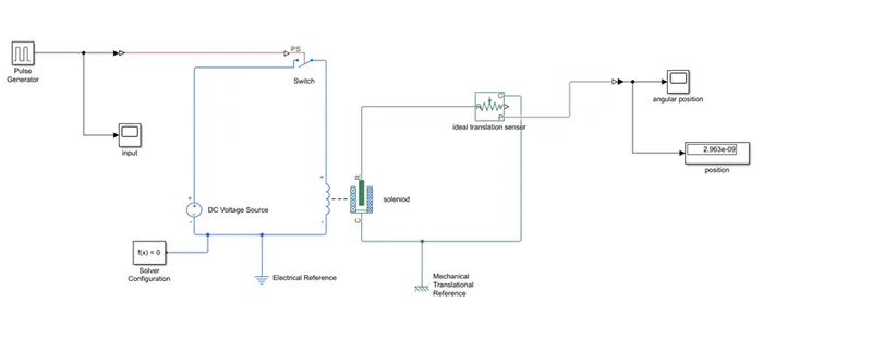
So we can observe the position and velocity of the solenoid by using ideal translational motion sensor and output results are displayed and plotted by using scope.
Battery:
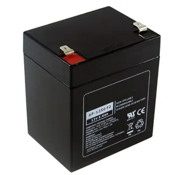
An electric battery is a source of electric power consisting of one or more electrochemical cells with external connections for powering electrical devices.
When a battery is supplying power, its positive terminal is the cathode and its negative terminal is the anode. The terminal marked negative is the source of electrons that will flow through an external electric circuit to the positive terminal. When a battery is connected to an external electric load, a redox reaction converts high-energy reactants to lower-energy products, and the free-energy difference is delivered to the external circuit as electrical energy. Historically the term "battery" specifically referred to a device composed of multiple cells; however, the usage has evolved to include devices composed of a single cell.
Solenoid:
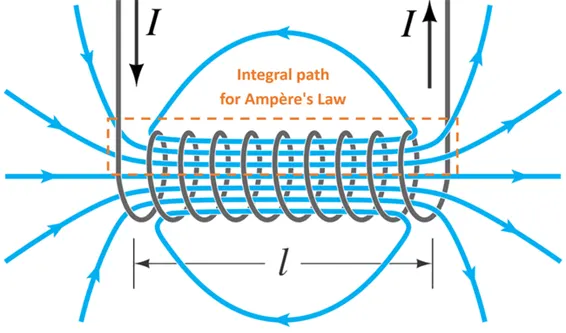
A solenoid is a long piece of wire which is wound in the shape of a coil. When the electric current passes through the coil it creates a relatively uniform magnetic field inside the coil.
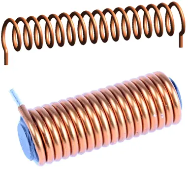
The solenoid can create a magnetic field from electric current and this magnetic field can be used to generate a linear motion with the help of a metal core. This simple device can be used as an electromagnet, as an inductor or as a miniature wireless receiving antenna in a circuit.
Working principle:
The solenoid can create a magnetic field from electric current and this magnetic field can be used to generate a linear motion with the help of a metal core. This simple device can be used as an electromagnet, as an inductor or as a miniature wireless receiving antenna in a circuit.
Most of the flux is concentrated only on the core, while some of the flux appears at the ends of the coil and a small amount of flux appears outside the coil.
The magnetic strength of the solenoid can be increased by increasing the density of the turns or by increasing the current flow in the coil.
Like all other magnets the activated solenoid has both Positive and Negative poles, through which an object can be attracted or repelled.
Block Diagram:
Ideal Translational Motion Sensor
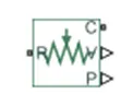
The Ideal Translational Motion Sensor block represents a device that converts an across variable measured between two mechanical translational nodes into a control signal proportional to velocity or position. You can specify the initial position (offset) as a block parameter.
The sensor is ideal since it does not account for inertia, friction, delays, energy consumption, and so on.
Connections R and C are mechanical translational conserving ports that connect the block to the nodes whose motion is being monitored. Connections V and P are physical signal output ports for velocity and position, respectively.
The block positive direction is from port R to port C. This means that the velocity is measured as v = vR – vC,
where vR, vC are the absolute velocities at ports R and C, respectively.
Pulse Generator
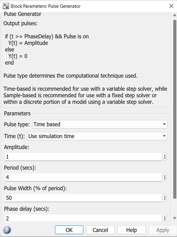
The Pulse Generator block generates square wave pulses at regular intervals. The block waveform parameters, Amplitude, Pulse Width, Period, and Phase delay, determine the shape of the output waveform. The following diagram shows how each parameter affects the waveform.

The Pulse Generator block can emit scalar, vector, or matrix signals of any real data type. To emit a scalar signal, use scalars to specify the waveform parameters. To emit a vector or matrix signal, use vectors or matrices, respectively, to specify the waveform parameters. Each element of the waveform parameters affects the corresponding element of the output signal. For example, the first element of a vector amplitude parameter determines the amplitude of the first element of a vector output pulse. All the waveform parameters must have the same dimensions after scalar expansion. The data type of the output is the same as the data type of the Amplitude parameter.
The block output can be generated in time-based or sample-based modes, determined by the Pulse type parameter.
Time-Based Mode
In time-based mode, Simulink® computes the block output only at times when the output actually changes. This approach results in fewer computations for the block output over the simulation time period. Activate this mode by setting the Pulse type parameter to Time based.
The block does not support a time-based configuration that results in a constant output signal. Simulink returns an error if the parameters Pulse Width and Period satisfy either of these conditions:
Depending on the pulse waveform characteristics, the intervals between changes in the block output can vary. For this reason, a time-based Pulse Generator block has a variable sample time. The sample time color of such blocks is brown
Simulink cannot use a fixed-step solver to compute the output of a time-based pulse generator. If you specify a fixed-step solver for models that contain time-based pulse generators, Simulink computes a fixed sample time for the time-based pulse generators. Then the time-based pulse generators simulate as sample based.
If you use a fixed-step solver and the Pulse type is Time based, choose the step size such that the period, phase delay, and pulse width (in seconds) are integer multiples of the solver step size. For example, suppose that the period is 4 seconds, the pulse width is 75% (that is, 3 s), and the phase delay is 1 s. In this case, the computed sample time is 1 s. Therefore, choose a fixed-step size of 1 or a number that divides 1 exactly (for example, 0.25). To ensure this setting, select auto on the Solver pane of the Configuration Parameters dialog box.
Sample-Based Mode
In sample-based mode, the block computes its outputs at fixed intervals that you specify. Activate this mode by setting the Pulse type parameter to Sample based.
An important difference between the time-based and sample-based modes is that in time-based mode, the block output is based on simulation time, and in sample-based mode, the block output depends only on the simulation start, regardless of elapsed simulation time
PS Switch block
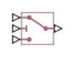
The PS Switch block compares the value of the physical signal presented at the second (middle) input port to the threshold value:
- If the control input value is greater than or equal to the threshold, the output is connected to the first input. This is the default connection shown in the block icon.
- If the control input value is less than the threshold, the output is connected to the third input.
The second (middle) input port is the control port and it never connects to the output.
All the inputs and the output are physical signals. Untyped physical ports facilitate unit propagation. Physical signals at the first and third input ports must have commensurate units. The unit at the output port is determined by unit propagation rules. For more information,
Input signal:
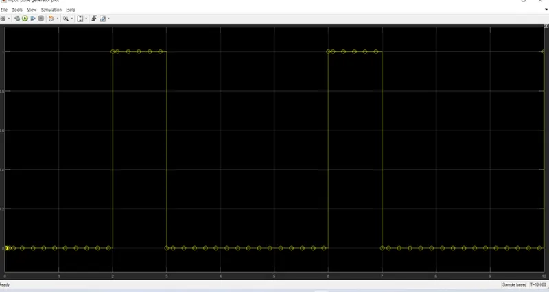
Pulse generator is produced input pulse should be zero for every 2 sec which represents an off condition so we create a pulse by changing the period to 4 which includes both on and off condition and pulse width is 50and phase delay of 2sec.output of pulse generator is connected to scope.
Output results:
The below plots are showing position of plunger and displacement of the motion sensor, and angular position. This is because of damping parameter will take the default values as one which is not critical for damping values and it is calculated by the formula 2
Where k is stiffness of the spring and m is mass of the plunger
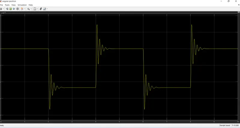
The plots shows the position of plunger for initial 2sec in which the switch is off condition the plot is constant, which indicates there is no deflection in the plunger and from 2-4 sec the plunger is in more negative position which indicates the plunger is move towards the bell.
- Use a thermistor to sense the temperature of a heater & turn on or turn off the fan as per the below conditions:
1.Temperature source: 20 °C from 0 to 10 seconds, 27 °C from 10 to 30 seconds, 23 °C from 30 to 50 seconds
- Fan conditions: ON if the temperature above 25 °C, OFF otherwis
Thermistor:
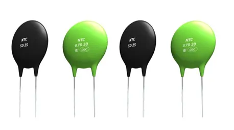
Thermistors, derived from the term thermal sensitive resistors, are a very accurate and cost- effective sensor for measuring temperature. Available in 2 types, NTC (negative temperature coefficient) and PTC (positive temperature coefficient), it is the NTC thermistor that is commonly used to measure temperature.
Signal builder:
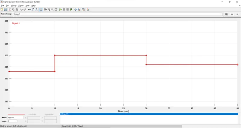
Signal builder block is used to set temperature for the controlled temperature
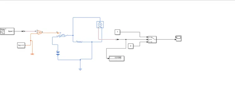
For 0-15 sec the temperature value is 293k(20 deg) and for 10-30 sec the temperature value is 300k(27 deg) and for 30-50 sec the value of temperature is 296k(23 deg) as per the problem statement.
This signal is provided to our heater through port S and port is linked with thermal reference.
Block diagram:
Explanation:
The temperature of heater is supplied to thermistor to sense it now in order to run the fan. When the temperature reaches the values of 25 deg(298 k) we have to trigger the circuit with some external supply of battery and as there is no device to calculated the resistance value from the thermistor for that another resistor is in series across thermistors
The voltage sensor is attached across the resistor to calculate the voltage drop into it and this voltage drop value is in putted as a threshold value to switch to start the fan. The fan will get on when the value is greater than 0.109
Output result:
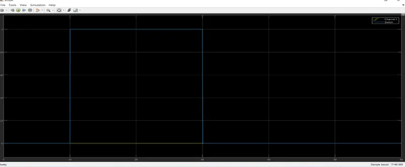
From the graph we can say that when the temperature is 20deg (293k) the fan is in off, and from it decrease to temperature more than 27 deg(300k) fan get on and again with temperature condition values to 23 deg(296k) fan gets switch off.
Conclusion: The doorbell and solenoid physical movements of plunger for t=2sec are obtained and plots the results using Simulink and MATLAB.
From the graph we can say that when the temperature is 20deg (293k) the fan is in off, and from it decrease to temperature more than 27 deg(300k) fan get on and again with temperature condition values to 23 deg(296k) fan gets switch off by using Simulink and MATLAB.