Week - 4
Aim : Implement control logic of a “washing machine” using Stateflow as per given sequence
CONTROL LOGIC OF WASHING MACHINE AND EXPLANATION:
- To create this control system in Simulink, insert the chart and create the logic system using state flow. The state flow executes the flow of inputs "if" the condition is accepted. In this control logic the input power is applied to ON the washing machine and the power supply is flow in other system. The conditions are applied to move other sequence of operation in state flow.
- Water supply is executed when power is ON, so entry and exit are assigned as value of 0 to 1. While the condition is not ok water supply stops and it will come back to its constant state.
This process is applied for each flow and time of working in each operation are initiate by sec that are given.
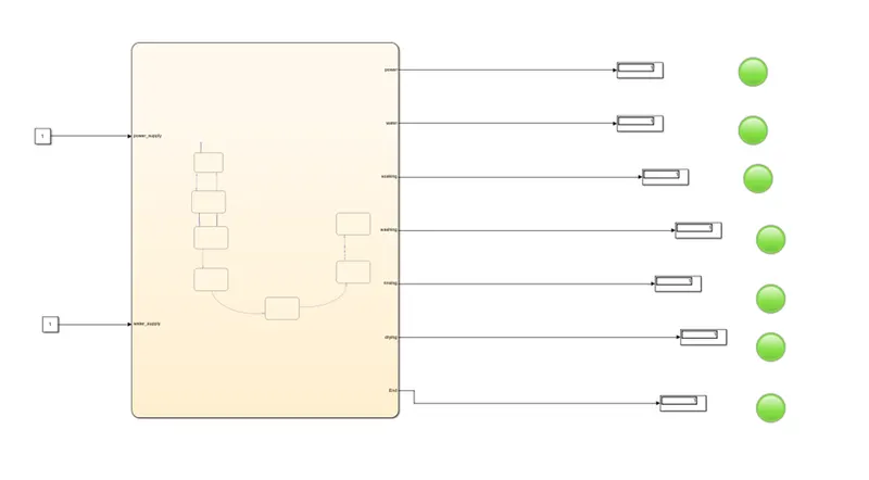
- State flow of washing machine are created and they are shown below
RESULT:
STUDY-1:
Simulink Model are created and inputs are generated to power supply and water supply
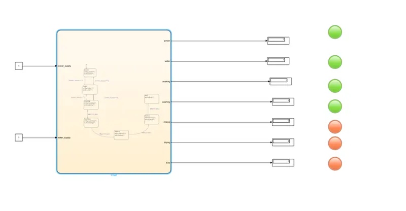
- If the power supply and water supply are assigned as 0 value the output value of all operations become zero because no inputs are generated and conditions are not applied. Lamp is in red colour due to 'OFF' of operation system. That are shown as below,
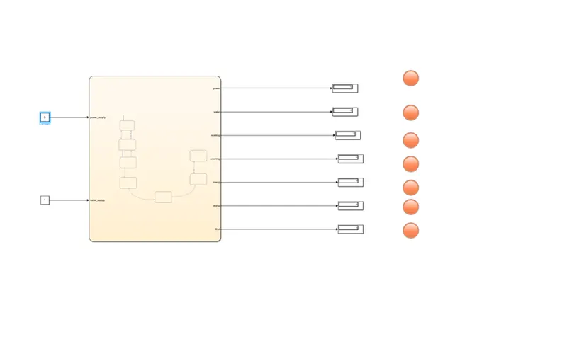
- In this state power supply is assigned as value I and water supply remain 0. The power is generated and that indicates as in display value I lamp is in green light. But the water supply is 0 so other operations are not proceeding that value as 0 and lamp is in red light.
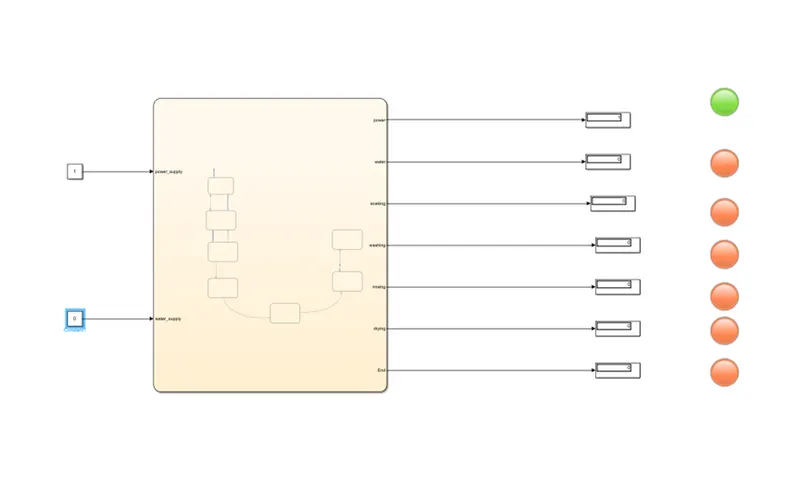
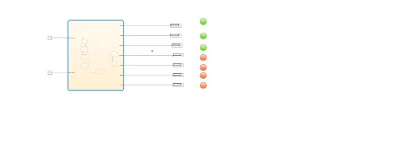
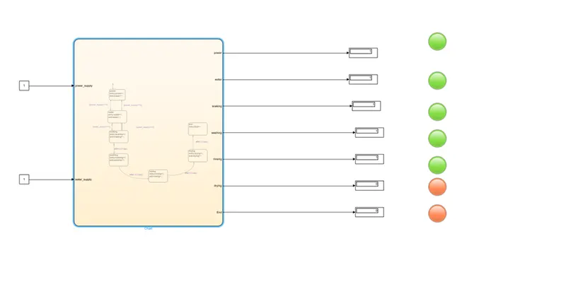
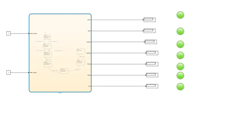
Now the power supply and water supply value are assigned as 1. Power is generated from input operation starts, water supply also done by initiate the value of 1 and the Sequence of operation in state flow starts when the condition is getting satisfied. Water supply is generated and other operations are followed by duration of time that we give in state flow. Each operation is run and results are obtained by display block. Lamp is turned "ON" and it indicates green colour as result.
Soaking:
Washing:
Rinsing:
Drying:
2.Draw Simulink chart for the "Gear shift" logic as per the given conditions:
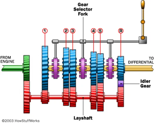
when we push the shifter towards the desired gear the gear looks into the man shaft and rotates it, thus the men shaft rotates at the speed of engaged gear and provides the output as per the gear's ratio. shifting of gears going from one gear to another by sliding or clicking the shifter. Downshifting means going to lower gears and decreasing the speed and upshifting means going to a higher gear and increase the speed
Blocks used in the model:
constant - To multiply with the slider gain. slider gain-It acts as a throttle to increase or decrease the speed.
state flow-control logic of gear shifting
Scope-To plot the graph of the speed vs gear shift.
Given data:
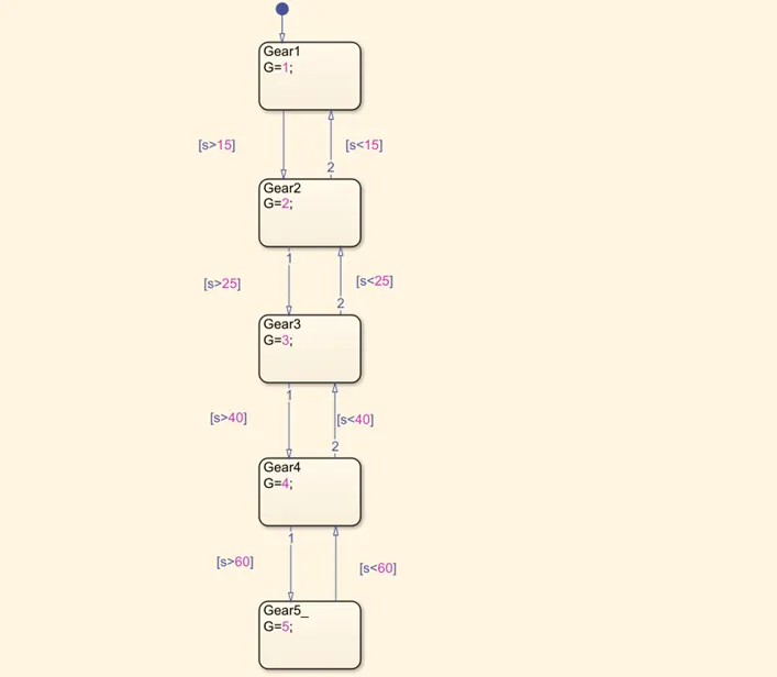
1st Gear (0-15 kmph)
2nd Gear (15-25 kmph
3rd Gear (25-40 kmph)
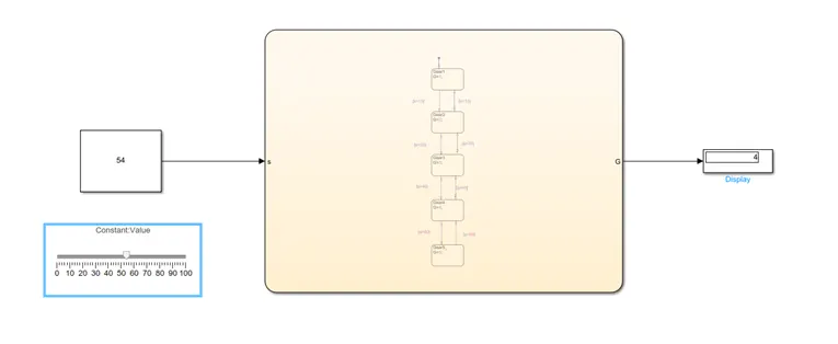
4th gear (40-60kmph)
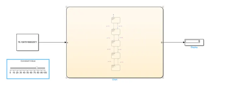
5th gear is above 60kmph.
Flow chart of gear system:
Output results:
1st Gear:
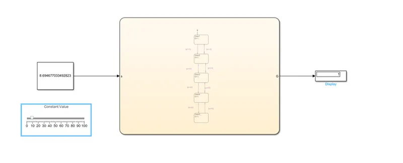
2nd Gear:
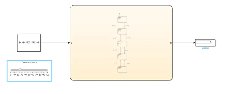
3rd Gear:
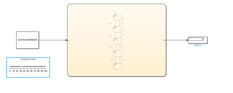
4th Gear:
5th Gear:
Conclusion:
For washing machine using data and condition design, the flow chart and run in different steps and obtain desire outputs by using Simulink and MATLAB.
By using given data design, the state flow chart operated in different speed and obtained desired output results by using Simulink and MATLAB.