Week-6 Challenge: EV Drivetrain
1) Which type of power converter circuits are employed in an electric and hybrid electric vehicle.
Power Converters:
A power converter is an electrical circuit that changes the electric energy from one form into the desired form optimized for the specific load. A converter may do one or more functions and give an output that differs from the input. It is used to increase or decrease the magnitude of the input voltage, invert polarity, or produce several output voltages of either the same polarity with the input, different polarity, or mixed polarities such as in the computer power supply unit.
Types of Power Converters used in EV or HEV
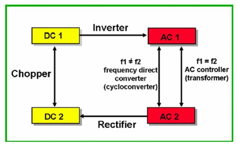
- AC – DC converter (Rectifier)
- DC – AC converter (Inverter)
- DC – DC converter (Chopper
AC – DC Converter (Rectifier)
The basic p-n junction diode that is used for the conversion of AC to DC can be referred to as a rectifier. This process is known as rectification. Based on its efficiency of converting AC to DC these rectifiers are chosen so that it can satisfy the essential requirements of the power supply unit in the electronic systems. Various basic electrical or electronic components are preferred in order to design rectifiers it can be diodes, MOSFET’S, etc. Considering the suitable application essential components are used and rectifiers are designed. A rectifier consists of single or multiple diodes as the basic necessity of the electronic components.
Application of AC-DC Converters (Rectifier) in EV or HEV
These rectifiers are used in the charging circuits of EV or HEV vehicles. The AC power supply from the grid or the charging station is converted to DC source to charge the battery by using the rectifier circuit.
DC – AC Converter (Inverter)
DC-AC converters convert the input DC power into AC power. These converters are also known as inverters. There are a lot of different types of inverters; however, a typical Inverter uses four switches or thyristors. The four switches make 2 pairs, individually controlled by a switching circuit where each pair is switched on at one interval of time. This alternating switching of the thyristors provides an alternating current through the load. This rhythm of turning the switches ON and OFF changes the DC voltage into AC across the load. The output voltage of the circuit can be directly controlled by changing the conduction time of the switch using the switching circuit.
Application of DC-AC Converters (Inverter) in EV or HEV
After charging the battery with the help of AC-DC converter to supply the AC motor we use DC-AC converter to convert DC supply from battery to AC to give supply to AC motor.
DC – DC Converter (Chopper)
DC-DC converters convert or change the voltage level of applied DC input into a desired level of DC output. These converters are also known as choppers, or a transistor chopper, or switching regulator.
The average output voltage of the converter circuit can be directly controlled by changing the conduction time of the controlled switch. The conduction time t of the switch is the product of the duty cycle and chopping period.
t = DT
where D is the duty cycle of the chopper and T is the chopping time.
Application of DC-DC Converters (Chopper) in EV or HEV
The DC-DC converter circuit is used in EV or HEV to step down the batter voltage to lower levels to supply for auxiliary components such as HVAC system, Infotainment system, Power windows, Lights etc.
2) An Electric Vehicle’s vehicles powertrain with 72V battery pack is shown in the diagram below. The duty ratio for acceleration operation is ‘d1’ and for braking operation the duty cycle is ‘d2’.
GIVEN PARAMETERS:
Rated Armature voltage (Va) = 72V
Armature current = 400A
Armature Resistance (Ra) = 0.5Ω
Motor Constant (k∅) = 0.7 Volt Second
Chopper switching frequency = 400 Hz
Vehicle speed - torque characteristics equation
Tϑ = 24.7+(0.0051) ω2
Duty Cycle = 70%
From the above given parameters
Vo = Va * Duty Cycle (The average voltage at the motor is given by the product of Rated voltage with the Duty cycle).
Vo = 72 * 0.7 = 50.4 V
From the given vehicle speed-torque characteristics
Tϑ = 24.7+(0.0051) ω2 - - - - - - - - -Equ (1)
We know that from speed-torque characteristics of the motor
ω = V/k∅ - (Ra/ k∅2) * T
from the above equation we can derive that
T = V(k∅/Ra)– ((k∅)2/ Ra) * ω
By substituting the values of the given parameters in the above equation
T = 50.4*(0.7/0.5) – (0.72/0.5) * ω
T = 70.56 – 0.98 ω- - - - - - - - -Equ (2)
As both the equations 1 & 2 are torque equations we can compare the equations
By comparing equ-1 & equ-2
24.7+(0.0051) ω2 = 70.56 – 0.98 ω
0.0051 ω2 + 0.98 ω + (24.7-70.56) = 0
0.0051 ω2 + 0.98 ω + (24.7-70.56) = 0
0.0051 ω2 + 0.98 ω – 45.86 = 0
By using the formula
`x= -b±(√(b^2-4ac))/(2a)`
ω`ω=-0.98±(√((0.98)^2-4*0.0051*-45.86))/(2*0.0051)`
ω1 = 38.91498
ω2 = -231.07185
as we can consider only the positive value
The steady state speed of the vehicle = 38.91 rad/sec.
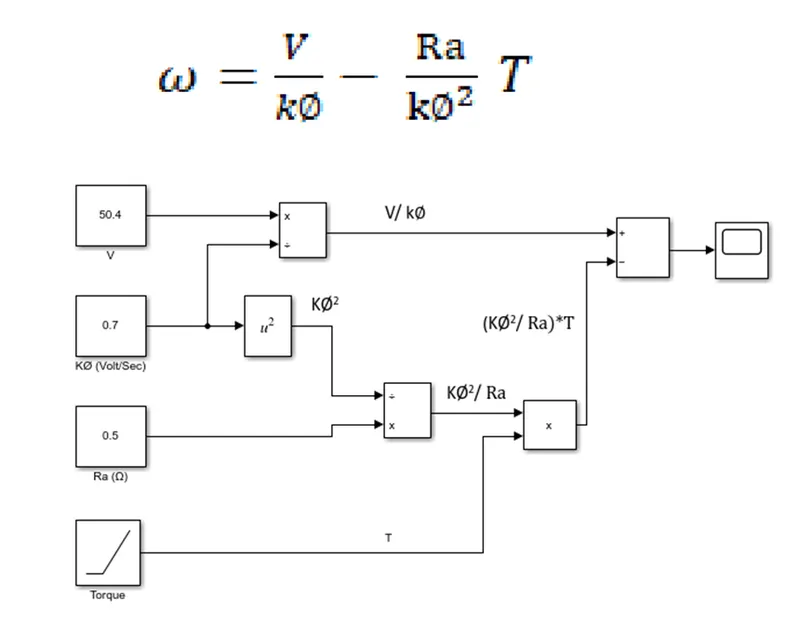
3) Develop a mathematical model of a DC motor for the below equation using Simulink.
`ω=V/(k∅)- (Ra)/(k∅^2) T`
Objective:
To develop a mathematical model of a DC motor for the equation `ω=V/(k∅)- (Ra)/(k∅^2) T` using Simulink.
Model:
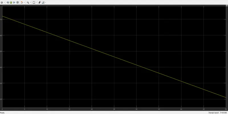
Result:
4) Refer to the blog on below topic.
Induction Versus DC brushless motors by Wally Rippel, Tesla
Explain in brief about author’s perspective.
Wally Rippel is a long-time proponent of electric vehicles. According to this blog wall rippel states that in the world of gas-powered vehicles all the engines are not same, there are flat heads, Hemis, Straight, opposed and V configurations and different engine models are suitable for different types of vehicles based up on the user requirements such as price and performance. He also states that the above statement is also applicable for electrical drives.
According to him at his time when he had hair on his head and used to carry a slider rule, there used to be lead acid batteries, DC brush motors, and contactor controllers. But today that is at the time when he was writing this blog Lead acid batteries have been replaced by Lithium-ion batteries and DC brush motors were replaced either by DC brushless or Induction motors, Contactors were replaced by Power Converters. He thinks that each of these elements also may become obsolete in near future or there may be a certain stability for these elements. He guesses that both Dc brushless and Induction machines last for many years and each will have its loyal proponents and religious detractors.
He describes the technologies involved in the DC Brushless and Induction Machines, how do they work, differences between them and the commons in between them.
DC Brushless Machine
With brushless machines, the rotor includes two or more permanent magnets that generate a DC magnetic field (as seen from the vantage point of the rotor). In turn, this magnetic field enters the stator core (a core made up of thin, stacked laminations) and interacts with currents flowing within the windings to produce a torque interaction between the rotor and stator. As the rotor rotates, it is necessary that the magnitude and polarity of the stator currents be continuously varied – and in just the right way - such that the torque remains constant and the conversion of electrical to mechanical energy is optimally efficient. The device that provides this current control is called an inverter. Without it, brushless motors are useless motors.
Author also describes that a brushless DC motor produces no starting torque when directly connected to fixed frequency utility power. They really need the aid of an inverter whose “phase” is maintained in step with the angular position of the rotor.
DC Brushless Machine
Unlike the DC brushless rotor, the induction rotor has no magnets – just stacked steel laminations with buried peripheral conductors that form a “shorted structure.” Currents flowing in the stator windings produce a rotating magnetic field that enters the rotor. In turn, the frequency of this magnetic field as “seen” by the rotor is equal to the difference between the applied electrical frequency and the rotational “frequency” of the rotor itself. Accordingly, an induced voltage exists across the shorted structure that is proportionate to this speed difference between the rotor and electrical frequency. In response to this voltage, currents are produced within the rotor conductors that are approximately proportionate to the voltage, hence the speed difference. Finally, these currents interact with the original magnetic field to produce forces – a component of which is the desired rotor torque.
Differences
|
DC Brushless Machine |
Induction Machine |
|
Rotor includes two or more permanent magnets |
Induction rotor has no magnets |
|
DC brushless drives require an absolute position sensor |
Induction drives require only a speed sensor |
|
Less rotor heat is generated |
Rotor heat generated is greater than DC brushless drive |
|
Peak point energy efficiency is generally higher |
Induction drive will typically be a few percentage points lesser than DC Brushless |
|
Can also operate at unity power factor |
The best power factor for induction drive is about 85% |
|
As the size of the machine increases the magnetic losses increase proportionately and part load efficiency drops |
As the size of the machine increases the losses do not necessarily grow |
Commons
- The stators for the 3-phase induction motor and the DC brushless motor are virtually identical. Both have three sets of “distributed windings” that are inserted within the stator core,
- Both drives use 3-phase modulating inverters.
Conclusion
The Author gave his conclusion that DC brushless drives will likely continue to dominate in the hybrid and coming plug-in hybrid markets, and that induction drives will likely maintain dominance for the high-performance pure electrics. The question is what will happen as hybrids become more electrically intensive and as their performance levels increase? The fact that so much of the hardware is common for both drives could mean that we will see induction and DC brushless live and work side by side during the coming golden era of hybrid and electric vehicles.