Simulation of EV powertrain and DC Motor modelling using Simulink
1. Which types of power converter circuits are employed in electric and hybrid electric vehicle?
There are different types of power converters employed in both the electric and hybrid electric vehicles. A following diagram indicates the different types of power converters used.
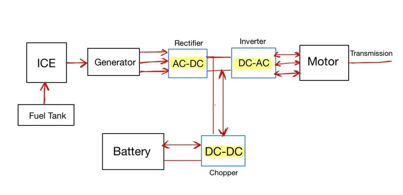
The various power converters are as follows :
DC-AC converter(inverter) : The inverters are used to convert the DC into AC. In an electric vehicle they are required because in most cases the motors are 3-phase induction motors which require AC supply, while the battery gives out supply in the form of DC. Hence, a power converter is used to convert the DC power from the battery into AC power required for the Motor. It can be seen in the above diagram, that before the motor, there is a DC-AC converter.
DC-DC converter (Chopper) : The DC-DC power converters are usually refferred to as choppers. These convert the DC voltage from one level to another. The vehicle requires the motor to operate in different speeds and since the voltage is proportional to the voltage, the voltage given to the motor must be variable, inorder for the speed to be variable. The battery output is always a constant DC voltage depending on the SOC. Hence, in order to obtain a different DC voltages from a constant DC value, a DC-DC converter is used, which can increase or decrease the DC voltage level depending on the requirement. These choppers can also be used to supply the battery power to the low voltage auxillary loads in the vehicle. In an electric vehicle or hybrid electric vehicle, the connection between the battery and the motor includes both a DC-DC converter and a DC-AC converter, as indicated in the diagram above.
AC-DC converter (Rectifier) : The rectifier is used to convert the AC supply into a DC supply. These are requried in electric vehicles for charging of the battery (either from the power grid or recharging from the engine and generator set in case of HEVs). Since transmission of AC power is highly efficient, the transmission of the power happens in AC, and hence the charging power grids have AC supply. In order to used them to recharge the battery, they have to be converted to a DC power supply, which is done using a rectifier. In HEVs, the engine runs the motor/generator (electric machine), which generates the electric power in AC, and inorder to store this energy into the battery, it is converted into DC supply by using a rectifier.
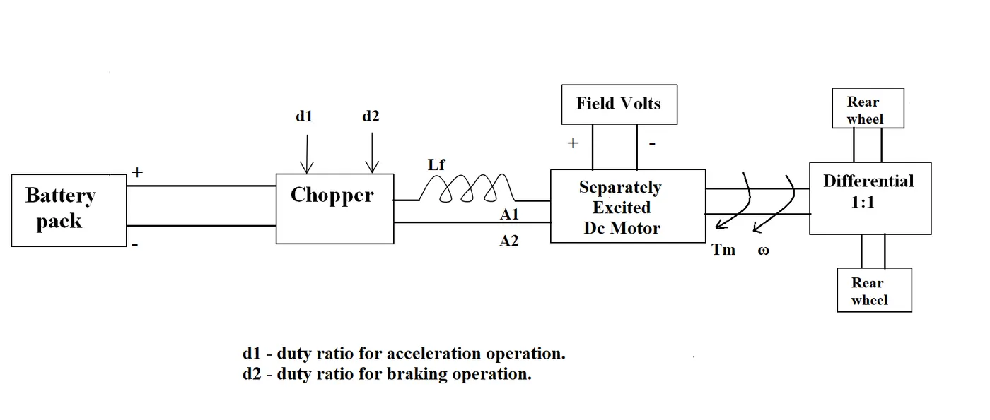
2. An Electric Vehicle's powertrain with 72V battery pack in shown in the diagram below. The duty ratio for acceleration operation is 'd1' and for the braking operation the duty ratio is 'd2'.
The vehicle speed-torque characteristics are given by the below equation

What is EV steady state speed if duty cycle is 70%?
Motor and Controller Parameters are as follows :
Rated Armature voltage= 72 V
Rated armature current= 400 A
Ra= 0.5Ω, KΦ= 0.7 Volt second
Chopper Switching frequency= 400 Hz
The differential ratio is 1:1, which indicates that the speed of the wheels and the speed of the motor is the same.
The motor being used is a seperately excited DC motor, the equation of the DC motor is :
`omega_m = V_(i n)/(K*phi) - R_a/(K*phi)^2*T_m`
`omega = 50.4/0.7 - 0.5/(0.7)^2*T = 72-1.02T`
Subtituting this in the given equation of vehicle speed-torque characteristics :
`T = 24.7 + (0.0051)*(72-1.02T)^2`
`T = 24.7 + 26.438 + 0.0053T^2 - 0.749T`
Hence, the equation to be solved is :
`T^2 -330T + 9648.68 = 0`
`T= 297.5757 Nm or 32.4243 Nm`
Calculating the speed using the equation : `omega = 72-1.02T`
we get `omega = 38.92`rad/s. or `omega = -231.527`rad/s.
Since the speed of the vehicle cannot be negative (assuming forward motion of the vehicle), the electric vehicle's steady state speed at 70% duty cycle is 38.92 rad/s .
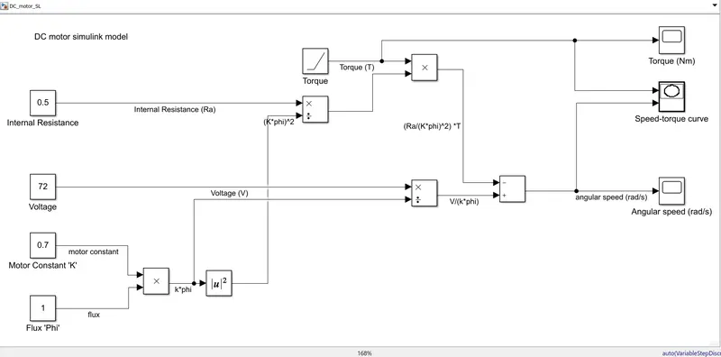
3. Develop a mathematical model of a DC Motor for the below equation using Simulink.
`omega_m = V_(i n)/(K*phi) - R_a/(K*phi)^2*T_m`
The simulink model developed is as follows :
Google drive link : https://drive.google.com/file/d/1M9eDEIsCdypQQUxWvtsID5WIuh_Vg5lt/view?usp=sharing
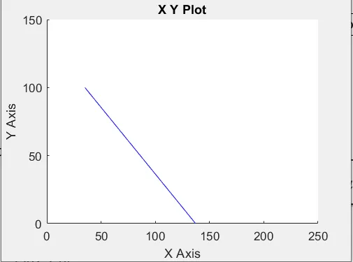
The model was simulated for 100 seconds. The torque is varied using a ramp signal from 0Nm with a slope of 1. The k*phi is kept at 0.7 units, internal resistance is kept at 0.5ohm, and the voltage is set at 96V, the speed-torque characteristics is plotted as follows. The speed is plotted in the X-axis, and torque in the Y-axis.
4. Refer to the blog on below topic on Induction vs DC brushless motors by Wally Rippel, Tesla, and Explain in brief about author’s perspective.
The authors explains about the two types of motors - DC brushless motors and Induction motors, and tries to determine which is better.
The author explores the two types - Induction motor and DC brushless motor, by explaining how the motors work in principle and states that on a broader level, both have similar stators and both use inverters, and the difference lies only in the rotors and inverter controls, and with the digital controllers, the difference are very small like the control code and sensors. The other difference is that induction motor rotors have no magnets.
Further the author explains the advantages and disadvantages of the two types, indicating that the in 3-phase induction motors torque is readily produced at the outset, and that they are directly compatible with the conventional utility. The disadvantages of the induction motors is that they need AC to operate, and have limited starting torque and limited running peak torque capabilities when compared to the DC type machines. They additionally require an inverter and feedback loops inorder to power the induction motor from DC and improve its performance. The DC brushless machines produce less rotor heat, and also operate at unity power factor. While in induction motors the magnetic losses are very less due to absence of magnets.
One main disadvantage of the DC brushless machines is that the losses increases as the motor size increases, while in induction motor the losses does increase with increasing motor size. Thus induction motor is favoured where higher performance is desired, wherein the peak effiiciency is less but the average efficiency is more. Added to this the Induction motors are also less costly, but they are very difficult to control. Hence, the author concludes that DC brushless motors will be dominant in the hybrid and plug-in hybrid markets, while induction motors will be favoured when higher performance pure electrics.
Both the types has its own advantage and disadvantage and hence the author believes that there is no clear winner. The author indicates that similar to different type of engine configurations (flat heads, V-configurations, striaght and others) still there in the market inorder to suit different personal requirements of price and performance, in the future both the types- Induction motors and DC brushless motors will be there competing in the electric vehicle market. With hybrid becoming more electrically intensive and higher performances required in the future, the author believes that the induction and DC brushless motors will work side by side.