Modelling and explanation of Electric Vehicle Powertrain and Drivetrain
Aim:
To explain about types of power converters used in hybrid and electric vehicles.
To derive the equation for EV steady-state speed if the duty cycle is 70%.
To develop a mathematical model of a DC Motor for the below equation using Simulink.
Explain in brief about Induction versus DC brushless motor by Walley ripple.
Introduction:
Due to the high power handling with higher efficiencies, these converters become an integral part of industrial electric drives, high electric power supplies, electric traction systems and automobile control equipment.
Introduction to Power Electronic Converters
Power electronic technology deals with processing and controlling the flow of electrical energy in order to supply voltages and currents in a form that is optimally suited for the end users’ requirements.
A power electronic converter uses power electronic components such as SCRs, TRIACs, IGBTs, etc. to control and convert the electric power. The main aim of the converter is to produce conditioning power with respect to a certain application.
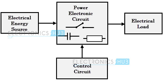
The function of power converters:
More properly called a voltage converter, this electrical device actually changes the voltage (either AC or DC) of an electrical power source.2 There are two types of voltage converters: step-up converters (which increase voltage) and step-down converters (which decrease voltage). The most common use of a converter is to take a relatively low voltage source and step it up to high voltage for heavy-duty work in a high power consumption load, but they can also be used in reverse to reduce voltage for a light load source.
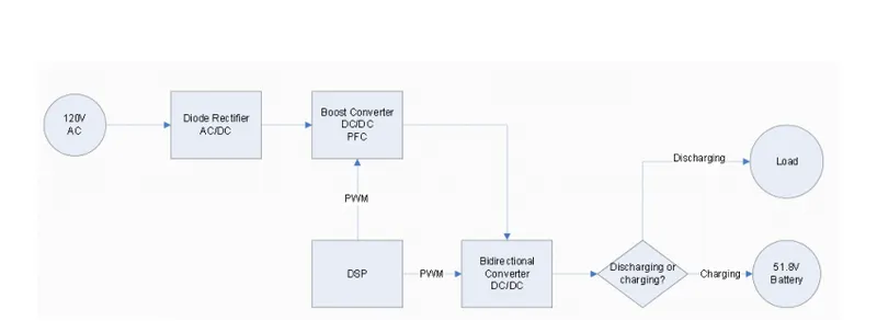
Depending on the type of function performed, power electronic converters are categorized into following types.
- AC to DC = Rectifier: It converts AC to unipolar (DC) current
- DC to AC = Inverter: It converts DC to AC of desired frequency and voltage
- DC to DC = Chopper: It converts constant to variable DC or variable DC to constant DC
- AC to AC = Cycloconverter, Matrix converter: It converts AC of the desired frequency and/or desired voltage magnitude from a line AC supply.
These types of power electronic converters may be found in a wide variety of applications such as switch-mode power supplies (SMPS), electrical machine control, energy storage systems, lighting drives, active power filters power generation and distribution, and renewable energy conversion, flexible AC transmission, and embedded technology. Let us go into detail about each converter.
AC to DC Converters or Rectifiers
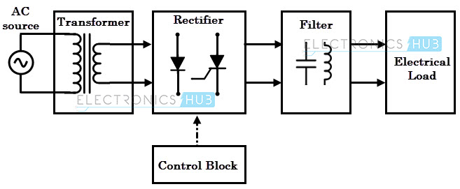
An AC to DC converter is also called a rectifier, which converts AC supply from main lines to DC supply for the load. The block diagram of an AC to DC converter is shown in figure below.
The essential components in this rectifier include a transformer, switching unit, filter and a control block.
DC to DC Converters
Many DC-operated applications need different levels of DC voltage from a fixed DC source.
Some of these applications include subway cars, DC traction systems, control of large DC motors, battery operated vehicles, trolley buses, etc. They require variable DC to produce variable speed, so a power conversion device is needed.
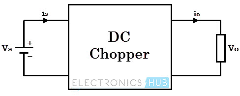
A DC chopper is a static device that converts a fixed input DC voltage to variable DC output or a fixed DC output of different magnitude (which can be lower or higher) than input value. The block diagram of a DC chopper is shown in figure below.
DC to AC Converters or Inverters
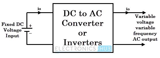
These converters are connected between DC source of fixed input, and variable AC load. Most commonly, these DC to AC conductor are called as inverters. An inverter is a static device that converts fixed DC supply voltage to variable AC voltage.
AC to AC Converters
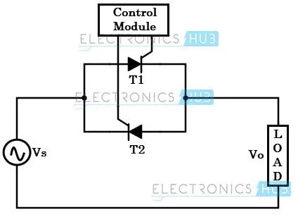
AC/AC converters connect an AC source to AC loads by controlling the amount of power supplied to the load. This converter converts the AC voltage from one level to the other by varying its magnitude as well as frequency of the supply voltage.
These are used in different types of applications including uninterrupted power supplies, high power AC to AC transmission, adjustable speed drives, renewable energy conversion systems, and aircraft converter systems.
Question-2
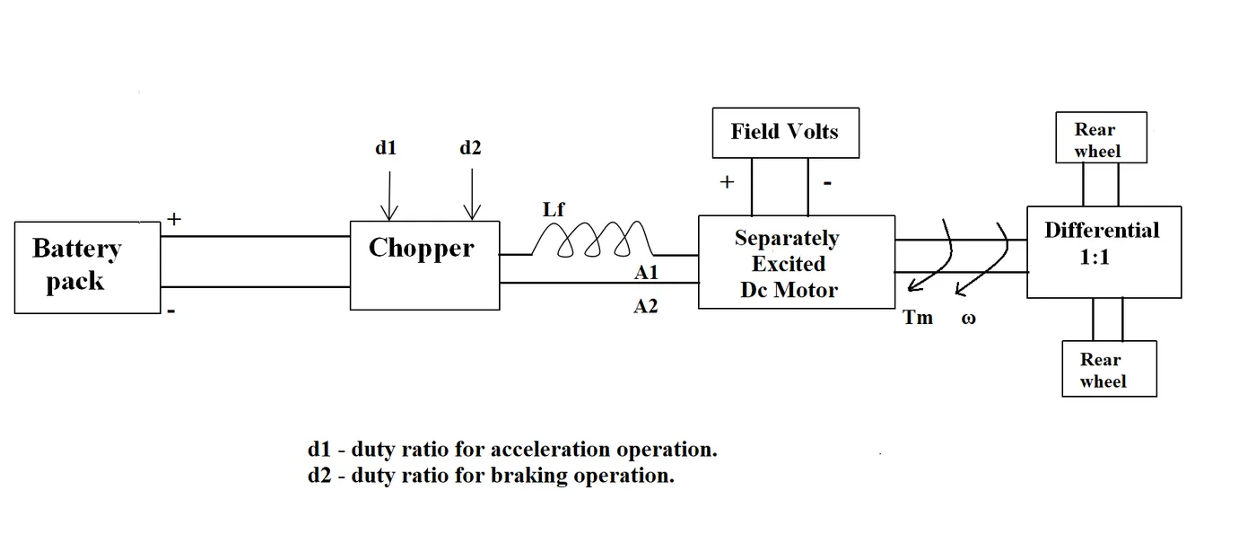
An Electric Vehicle's powertrain with a 72V battery pack in shown in the diagram below. The duty ratio for acceleration operation is 'd1' and for the braking operation the duty ratio is 'd2'.
The other parameters of the electric vehicle are given below,
Motor and Controller Parameters:
Rated Armature voltage= 72 V
Rated armature current= 400 A
Ra= 0.5Ω, Kϕ">ϕ = 0.7 Volt second
Chopper Switching frequency= 400 Hz
The vehicle speed-torque characteristics are given by the below equation
Tv=24.7+(0.0051)w^2 ----(1)
What is EV steady-state speed if the duty cycle is 70%
solution
Duty cycle=70%=70/100=0.7
actual voltage V=72*0.7=50.4V
V=50.4 volts
We have the torque equation for motor:
T=((V-(ω">ω*Kt))./Ra).*Kt ------(2)
Now we have 2 equations for torque (T), by equating that two-equation the unknown variable of w(speed) can be found.
By subsistuting the given data:
24.7+(0.0051)ω">ω^2 = (50.4-0.7*ω">ω)/0.5)*0.7
24.7+(0.0051)ω">ω^2 = (50.4 - 0.7ω">ω)*1.4
24.7+(0.0051)ω">ω^2 = 70.56 - 0.98ω">ω
By simplify the two equation
(70.56-24.7)+((0.0051)ω">ω^2)+0.98ω">ω)=0
45.86+(((0.0051)W^2))+0.98w)
By solving the above equation W is taken as positive
ω">ω=38.915 rad/sec
To convert was (rad/sec) to rpm N
N(rpm)=60*w/2*pi
N=60*38.9154/2*3.14
N=371.914 rpm
So, the E.V steady-state speed if the duty cycle at 70% is 371.914 RPM.
Objective.3
Develop a mathematical model of a DC Motor for the below equation using Simulink.
ω">ω= V/Kϕ">ϕ -Ra/Kϕ">ϕ^2 .T
Given
By using the above equation and formula we can find the torque value
T=24.7+(0.0051)38.914^2
T=32.4229
v=50.54 volts
Kϕ">ϕ =0.7
Ra= 0.5Ω
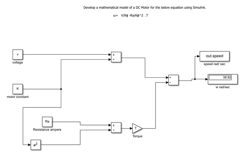
simulink model
matlab model
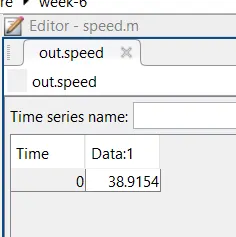
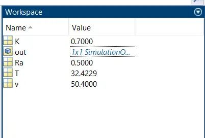
From the Simulink model, I can find out the output w and saved in the Matlab workspace.
objective -4
The blog is about the walley respected about Brushless D.C motor and induction motor. Walles is a proponent of E.V.He was an engineer
Induction versus DC brushless motor by walley ripple
According to the author's perspective, Firstly he gave the description of the DC brushless motor its parts and
specifications and what is called and the next description of the Induction motor is the components and working of the induction motor. Then he compared the DC brushless and induction which he mentioned that 3- a phase induction motor can produce the output torque produce output torque and also have an ability to start under the load without any inverter, as of DC brushless motor produces no starting torque when directly connected to fixed frequency utility power and also inverter is needed to start under load. Then he discussed the limitations of the 3- Phase induction motor they cannot operate from DC; AC is a must. Shaft speed is proportionate to line frequency. Hence, when used with utility power, they are constant speed machines. Finally, when operated from utility power, they have limited starting torque, and some ew ha t limited running peak torque cap abilities when compared to DC type machines. The inverter can be added to 3 - Phase induction so that we can supply power from a DC source or Battery and also we can get the variable speed and can adjust the frequencies.
Then he discussed as the only main difference between DC brushless and Induction motor is of control code and also the rotor of DC brushless gets less heated at peak torque than that of Induction motor rotor.
Then he discussed the losses when the motor runs which is the induction machine when operated with a sum art inverter has an advantage over a DC brushless machine - magnetic and conduction n losses can be traded with the efficiency increases proportionally and This advantage becomes increasingly important as performance is increased. With DCbrushless, as machine size grows, the magnetic loss part-load efficiency drops. With induction n, as machine size grows, losses do not grow, Thus., induction drives may be the favored approach h where high - performance is desired; peak efficiency will be a little less than with DC brushless, but average efficiency may be better He concluded with that DC brushless drives will likely continue to dominate in the hybrid and coming plug-in hybrid markets, and that induction drives will likely maintain dominance for the high-performance pure electrics.