Week-6 Challenge: EV Drivetrain
1. Which types of power converter circuits are employed in electric and hybrid electric vehicle?
Solution: The demand of electrical power in vehicular application is growing rapidly as the mechanical components are being replaced by the elctrical and electronic components. it is expected that the power demand. In order to accomplish the growing poweer demands of EVs in desired manner, integration of power electronic components with electrical and mechanical loads of vehicle becomes crucial. The integration of power electronic converter not only improves the overall performance and fuel economy but also reduces the emission as well as weight and size of the vehicle. For electrical vehicular system, there is a need of highly reliable, flexible and fault tolerant electrical power processing system on board to deliver high quality of power based on vehicle demands. At present, this responsibility have been taken care by the available power electronic converter that includes DC/DC converters, rectifiers DC/AC, inverters AC/DC. Individually or combination of these converters can be taken to serve the purpose, however operation of each Power electronic converter is entirely different from the other. Power electronic converter perform some of the critical tasks like ON/OFF switching of various loads, Power conditioining and voltage/current modulation to create compatibility among the energy source system, traction motors and auxilary loads. Power electronic converters not only serve the purpose of converting electrical power from one form to another (DC/DC, DC/AC and AC/DC) but also help to step up and step down the system voltage level. The following figure shows the classification of Power Electronic converters
In this the major conerters are explained below.
DC to DC Converter: In electrical engineering, a DC to DC converter is a category of power converters and it converts unregulated DC input voltage at a certain level to a regulated DC output voltage at a different level with very high conversion efficiency i.e. >90%. And in other terms it is an electric circuit which converts a source of direct current DC from one voltage to another by storing the input energy temporarily and then releasing the energy to the output at a different voltage. The storage may be in either magnetic field storage components(inductors, transformers) or electric field storage components (capacitors). DC/DC converters can be designed to transfer power in only one direction, from the inout to output. However, almost all DC/DC converter topologies can be made bi-directional. A bi-directional converter can move power in either direction, which is useful in applications requiring regenrative braking. The amount of power flow between the input and the output can be controlled by adjusting the duty cycle(ratio of ON/OFF time of the switch). Usually this is done to control the output voltage, the input current, the output current, or to maintain a constant power. Modern day DC/DC converters are operated at high frequencies (10khz - 1Mhz). The size of the components such as inductors, transformers and capacitors are reduced at high frequency operation. Transistors such as MOSFETs and IGBTs are used as switches. The former is preffered in high frequency, low and medium power applications, whereas the latter is preffered in low frequency high power applications. The switches are turned ON/OFF by Pulse Width Modulation (PWM) technique. In addition, the role of DC/DC converter is very significant especially in terms of better utilization of energy sources, power management, dynamic performance, flexibility, system optimization and reduction of weight and cost. In previous days, the voltage was raised from its earlier 6V level to the present day 12V level and, now with a ever increasing demand forecasted into the future, there is a need to switch over to much higher voltage levels of 42V,300V or higher due to high voltage levels being produced in HEVs, it becomes essential to have DC/DC converters to supply all the auxilary loads to the vehicle. The following figure shows the DC/DC converter location in an EV.
DC to AC Converters: A suitable DC/AC inverter draws the DC power from the batteries to drive the electric traction motor, which in turn provides power to the wheels. The DC/AC inverter also performs the function of recharging the batteries during regenerative braking in HEVs. Also inverters are used for suppluing utility loads such as air conditioning and power outlets. Inverters are generally classified into voltage-fed and current-fed types. Because of the need of a large series inductance to emulate a current source, current-fed inverters are seldom used for EV propulsion. In fact, voltage-fed inverters are almost exclusively used because they are simple and can have power flow in either direction. The following diagram shows the basic architecture of the converters used.
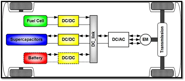
AC to DC Converters: AC/DC converters are are electrical circuits that transform alternating current AC input into direct current DC output. AC/DC converters are also called as rectifiers they convert the AC voltage to variable DC voltage, then optimize it through a filter to obtain an unregulated DC voltage. These converters are most commonly used in Plug in Hybrid Electric Vehicle (PHEV) and Plug in Electric Vehicle (PEV). These vehicles get their propulsion power from an external energy source(charging stations) which is in the form of AC and battery needs to be charged by using a DC source. AC/DC converter supplies electric power from a commercial power system to an Onboard high-voltage bettery. The AC/DC converter is required to work more eficiently to shorten the charging time and also to be downsized so as to be fitted in a restricted space. The problems lie in large and heavy coil parts and large power loss accompanied with high frequency switching. The following figure shows the detailed view of Power electronic converters.
2. An Electric Vehicle's powertrain with 72V battery pack in shown in the diagram below. The duty ratio for acceleration operation is 'd1' and for the braking operation the duty ratio is 'd2'.
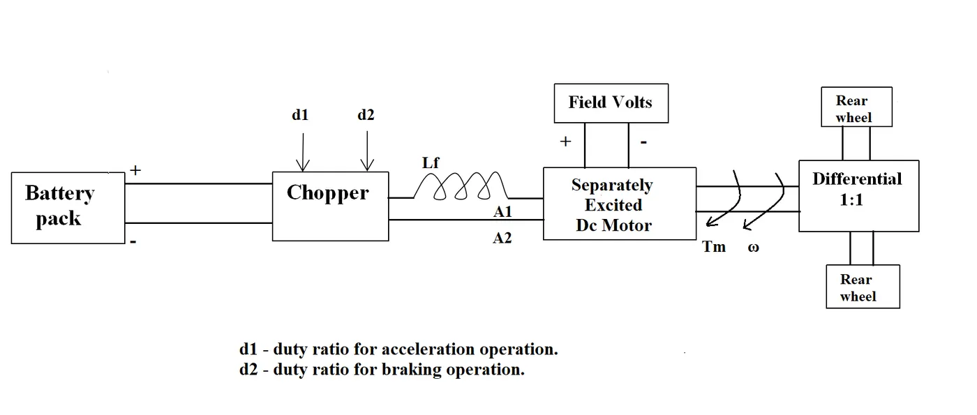
The other parameters of the electric vehicle is given below,
Motor and Controller Parameters:
Rated Armature voltage= 72 V
Rated armature current= 400 A
Ra= 0.5Ω, KΦ= 0.7 Volt second
Chopper Switching frequency= 400 Hz
The vehicle speed-torque characteristics are given by the below equation

What is EV steady state speed if duty cycle is 70%?
Solution: Given data is,
Batter pack voltage (V) = 72V
Rated armature current = 400A
Armature resistance Ra = 0.5Ω
Motor constant KΦ = 0.7 v.s
Chopper switching frequency = 400HZ
Speed Torque Characteristic equation is Tv = 24.7+(0.0051)w²
Duty cycle = 70% = 0.7
we have to calculate the EV steady state speed at 70% duty cycle = ?
Considering the Torque-speed equation,
Tv = (Vv×kΦ)/Ra - ((kΦ)²/Ra)×w
where,
Vv = Vechile voltage = Battery voltage × Duty cycle = 72 × 0.7 = 50.4V
Vv = 50.4V
kΦ = Motor constant
Tv = Vehicle torque in Nm
Ra = Armature resistance in ohms
w = Steady state speed in Rad/sec
now substituting all the values in the equation,
Tv = (Vv×kΦ)/Ra - ((kΦ)²/Ra)×w
Tv = (50.4 × 0.7)/0.5 - ((0.7)²/0.5)×w
Tv = 70.56 - 0.98w
By comparing it with the given characteristic equation Tv = 24.7+(0.0051)w²
we can write as,
70.56 - 0.98w = 24.7+(0.0051)w²
0.0051w² + 0.98w - 45.86 = 0
This equation is in the form of a quadratic equation, ax²+bx+c=0
so we can solve the equation by using a quadratic formula x = (-b ±(√b²-4ac))/2a
Here x=w, a=0.0051, b=0.98, c=-45.86
so by solving the above quadratic equation by using the formula will get values as
w = 38.92 rad/sec and w = -231.07 rad/sec
will always consider the speed value in positive so,
Steady state speed of an Ev at 70% duty cycle w is 38.92 rad/sec or 368.15 RPM.
3. Develop a mathematical model of a DC Motor for the below equation using Simulink.
ω">ωω= V/Kϕ">ϕϕ -Ra/Kϕ">ϕϕ^2 .T
Solution:
Here we are developing a mathematical model of Dc motor using simulink,
The equation to develop the model is
ω">ω = V/Kϕ">ϕϕ -Ra/Kϕ">ϕϕ^2 .T
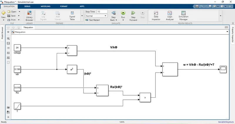
So for this equation we have a model which is shown in the following figure.
here we have taken the values as,
V = 24V
kΦ = 0.136
Ra = 0.016Ω
in the place of T we have taken a ramp block.
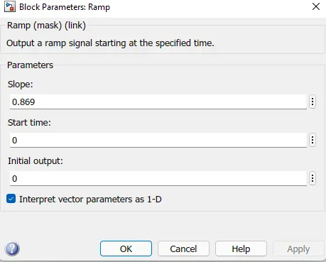
we have given a slope value as 0.869,
because as we have discussed in the class the slope is represented by Ra/(kΦ)²
so by substituting the values 0.016/0.136² = 0.869.
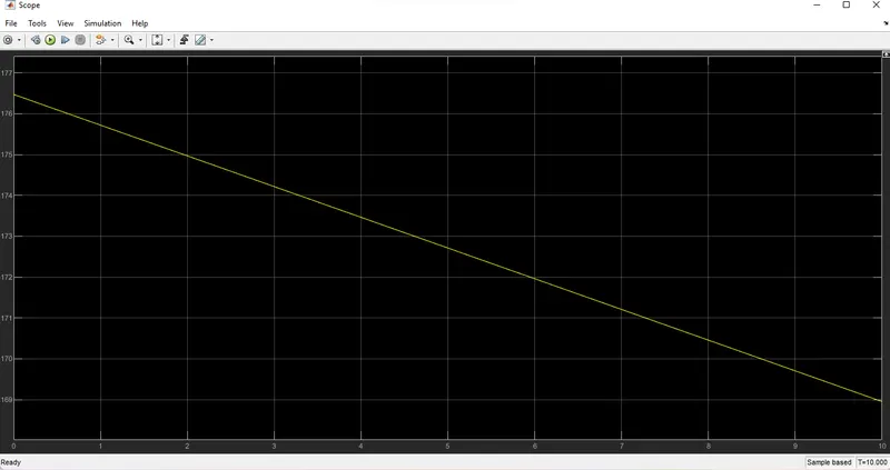
By giving all the values i have run the program. And following plot has been observed from the scope block as a result. Here on x-axis we are taking the time values in sec and on y-axis w values are taken in terms of rps.
4. Refer to the blog on below topic:
Induction Versus DC brushless motors by Wally Rippel, Tesla
Explain in brief about author’s perspective?
Solution: The author Wally Ripple who worked as an engineer at AeroVironment and helped to develop the EV1 for general motors. Wally has also worked for the Jet propulsion laboratary on electric vehicle battery research. In this blog he explains about the differences, advantages and limitations of Induction and Dc brushless motor. And compared the previous era and upcomin era based on his experience.
First of all he want to clear us a point that not only one particular engine is best. There are many engines and every engine has its own specifications and requirements. Engines are useful depending upon the personal requirements such as price and performance. And he said a point based on his experience that in the previous days Lead acid batteries are used and now they are replaced by Lithium and in the same way DC brush motors are replaced by DC Brushless and induction motors. And as per his guess there will be a stability in the use of two motors because of its proponents and religious detractors.
Next he discussed about the working, differences and similarities of both DC Brushless and Induction motor.There are 2 or more permanent magnets in the DC Brushless. whereas Induction motor(IM) has no magnets its just stacked steel laminations with buried peripheral conductors that form a shorted structure. In case of DC Brushless it is necessary to vary magnitude and polarities of the stator currents continuously, such that the torque will remains constant. and conversion of electrical energy to mechanical energy is efficient. Inverter provides the current control in this case. But without it Brushless motors are useless. In induction motors there is no such devices are required.
Coming to 3-Φ IMs, the startor for the 3-Φ IM and Brushless motors are identical. Bith have 3 sets of distributing windings that are inserted within the stator core. The essensial difference between the 2 machines is with the rotor. The 3-Φ IM have great utility but still they also have some severe limitations like they cannot work from DC, AC is must to operate. Basically these are constant speed machines and have limited starting torque and limid running peak capabilities. By adding an inverter it is possible that IM can operate from a battery or other Dc source. Variable speed is also possible with it, but torque performance is still low compared to DC Brushless machine.
He said that in 1990's all the EVs except one were powered by DC Brushless but today all the hybrids are powered by DC Brushless drives. One of the main difference is less rotor heat is generated with the DC Brushlessdrive. Rotor cooling is also easier and peak point efficiency is also higher. And coming to power factor, DC Brushless moor can also operated at unity power factor but in case of IMs the best operating power factor is about 85%.
Later he discussed about the limitations, In ideal Brushless drives, strength of magnetic field(B) produced by permanent magnets would be adjustable, such that the sum of eddy,hysteris and i² losses are minimized. But there is no easy way to change B with permanent magnets. In case of IMs there is no magnets so the B value can be adjustable so losses can be reduced and efficiency can be maximized. This advantage becomes increasily important as performance is inreased. So when high performance is required IMs are favoured. Coming to permanent magnets they are expensive, due to there is no magnets IMs will retains a cost advantage. But he also said that controlling of IM is more difficult i.e. achieving stability over the entire torque-speed range and over the temperature is more difficult so which added the developments costs, but likely little or no recurring costs.
Coming to his conclusion about both motors, DC Brushlesss drives will continue to dominate in Hybrid and coming Plug in Hybrid models. Whreas Induction Motors will dominate in high performance pure Electric Vehicles. As he said that the hardware is common for both drives. It means that may will see both the drives works side by side in the upcoming era of Hybrid and Electric Vehicles.