Week-6 Challenge: EV Drivetrain
1)AIM : Which types of power converter circuits are employed in electric and hybrid electric vehicle?
introduction:
Power electronic circuts are also called as power converters.
A converter use semiconductor switches to convert electrical power at high efficiency.switches used are diodes,transistors or thyristors.
converters/controllers are classified into main categories:
1) Diode rectifiers: Rectifier circuit converts ac input voltage into a fixed dc voltage. these are uncontrolled rectifiers.
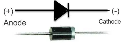
2) Phase controlled rectifiers (AC to DC Converter): AC to DC converters are used to obtain fixed DC supply from the AC supply of fixed voltage.
The very basic diagram of AC to DC converters is like.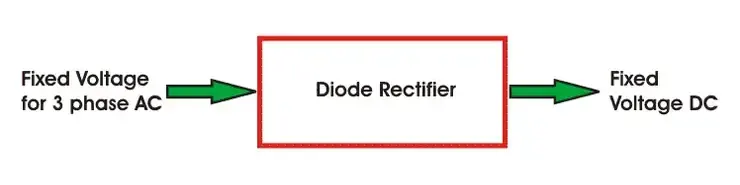
3) Choppers (DC to DC Converter): Choppers or DC-DC converters are used to get a variable DC voltage.
Power transistors,IGBT's GPO’s,power MOSFET's are mainly used for this purpose.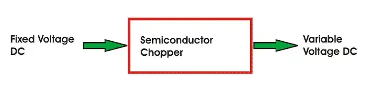
4) Invertes (DC to AC converter): Inverters are used to get AC from DC, the operation is just opposite to that of AC to DC converters.
PWM semiconductors are used to invert the current.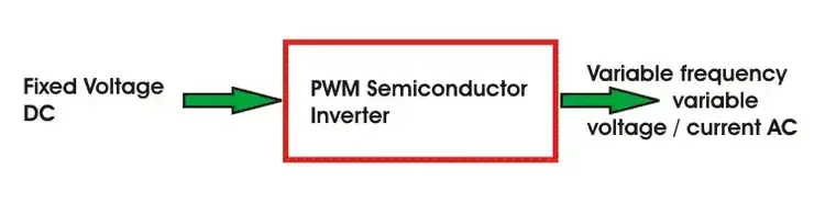
5) AC converters cycloconverters (AC to AC converters): Cycloconverters are used to convert the fixed frequency and fixed voltage AC into variable frequency and variable voltage AC.
Thyristors are used in these converters to control the firing signals.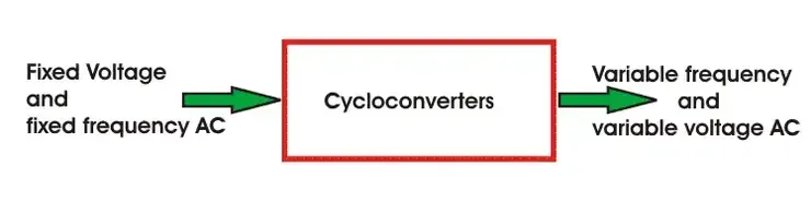
6) AC voltage controllers (AC regulators): AC Regulators are used to obtain the regulated AC voltage, mainly autotransformers or tap changer transformers are used in this regulators.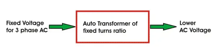
2) AIM: An Electric Vehicle's powertrain with 72V battery pack in shown in the diagram below. The duty ratio for acceleration operation is 'd1' and for the braking operation the duty ratio is 'd2'.
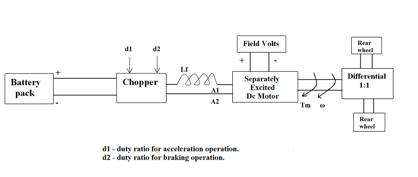
The other parameters of the electric vehicle is given below,
Motor and Controller Parameters:
Rated Armature voltage= 72 V
Rated armature current= 400 A
Ra= 0.5Ω, KΦ= 0.7 Volt second
Chopper Switching frequency= 400 Hz
The vehicle speed-torque characteristics are given by the below equation

What is EV steady state speed if duty cycle is 70%?
Solution:
The parameters of the electric vehicle is given motor and controller parameters
rated armature voltage=72v
rated armature current=400a
armature resistance =0.5ohm's
KΦ= 0.7 Volt second
Chopper Switching frequency= 400 Hz
The vehicle speed-torque characteristics are given by the below equation
The duty cycle is given as 70%.
The average voltage is given by
Vo =supplied voltage × duty cycle
Vo =72×70/100
Vo =50.4v
The dc motor torque- speed eq
Tm=vo-kϕ/ra -(k ϕ)^2*w/ra
Tm=50.4*0.7/0.5-(0.7)^2*w/0.5
Tm=70.56-0.98w
vehicle speed-torque and motor torque speed
Tv=Tm
24.7+(0.0051)w^2=70.56-0.98w
0.0051w^2+0.98w-45.86=0
solving quadratic equation using the formula
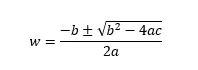
substituing the valuse.
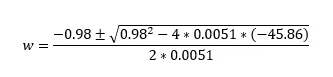
solving the eq we get two different values
w=38.914
w=-231.071
vehicle steady state speed is
w=38.914 rad/sce.
3) AIM Develop a mathematical model of a DC Motor for the below equation using Simulink.
DC motor equation using simulink blocks:
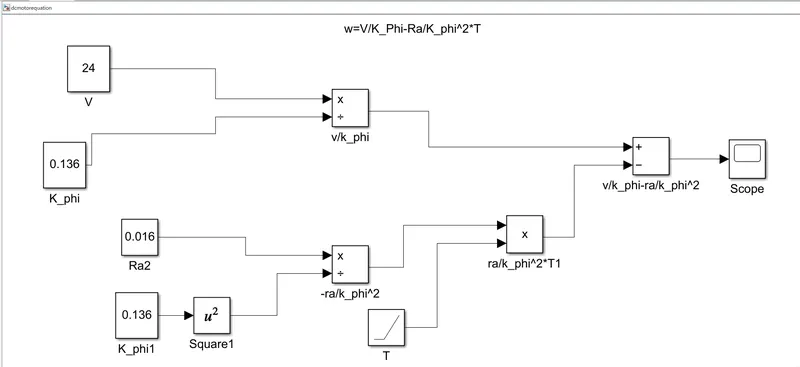
- the using 4 constant blocks for give it names v,k_phi,ra,k_phi.
- using the square block the value of k_phi^2.
- using the two divie blocks connected with the two values. and the output of the divie blocks are connected subtract block.
- one ram block are using value of the T. the subtracte block output are connected to the scope.
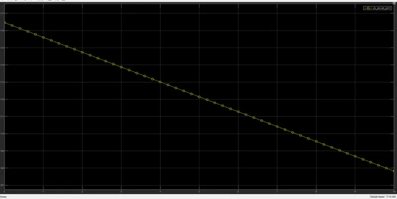
- scope get the output result.
output:
4) AIM Refer to the blog on below topic:
Induction Versus DC brushless motors by Wally Rippel, Tesla
Explain in brief about author’s perspective.
Dc brushless motor:
With brushless machines, the rotor includes two or more permanent magnets that generate a DC magnetic field .
In turn, this magnetic field enters the stator core and interacts with currents flowing within the windings to produce a torque interaction between the rotor and stator.
As the rotor rotates, it is necessary that the magnitude and polarity of the stator currents be continuously varied – and in just the right way - such that the torque remains constant and the conversion of electrical to mechanical energy is optimally efficient.
The device that provides this current control is called an inverter.
Without it, brushless motors are useless motors.
Unlike the DC brushless rotor, the induction rotor has no magnets.
Currents flowing in the stator windings produce a rotating magnetic field that enters the rotor.
In turn, the frequency of this magnetic field as “seen” by the rotor is equal to the difference between the applied electrical frequency and the rotational “frequency” of the rotor itself.
Accordingly, an induced voltage exists across the shorted structure that is proportionate to this speed difference between the rotor and electrical frequency.
In response to this voltage, currents are produced within the rotor conductors that are approximately proportionate to the voltage, hence the speed difference.
Finally, these currents interact with the original magnetic field to produce forces – a component of which is the desired rotor torque.
Induction motor:
induction motor drives. A forerunner of the 3-phase induction motor was invented by nikola tesla sometime before 1889.
Curiously, the stators for the 3-phase induction motor and the DC brushless motor are virtually identical.
Both have three sets of “distributed windings” that are inserted within the stator core. The essential difference between the two machines is with the rotor.
When a 3-phase induction motor is connected to utility type 3-phase power, torque is produced at the outset.
the motor has the ability to start under load.
No inverter is needed.
The fact that induction motors are directly compatible with conventional utility power is the main reason for their success.
In contrast, a brushless DC motor produces no starting torque when directly connected to fixed frequency utility power.
They really need the aid of an inverter whose “phase” is maintained in step with the angular position of the rotor.
While 3-phase induction motors have great utility, they also have some severe limitations.
They cannot operate from DC; AC is a must. Shaft speed is proportionate to line frequency.
Hence, when used with utility power, they are constant speed machines.
Finally, when operated from utility power, they have limited starting torque and somewhat limited running peak torque capabilities,when compared to DC type machines.