Project
AIM: Carry out a system-level simulation of an all-terrain BAJA vehicle.
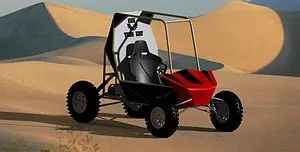
All Terraiin Vehicle:
A small open motor vehicle with one seat and three or more wheels fitted with tyres, designed for use on rough grounds.
ATVs are motorized vehicles that are meant to be used off-road or on drit roads, not on paved roads or highways.
they usually have four large balloon-style tries,with a seat in the middle that a rider straddles while steering by the handlebars.
Continous Variable Tranmission(CVT):
A Continously Variable Transmission (CVT) is an automatic tranmission system that can change seamlessly thtough a continuous range of gear ratios.
This contrasts with other transmissions that provide a limited number of gear ratios in fixecd steps.
The flexibillity of a CVT with suitable control may allow the engine to operate at a constant RPM while the vehicle moves at varying speeds.
CVTs are used in automobils,tractors,motor,scooters.
the most common type of CVT uses two pulleys connected by a belt or chain, however,several other designs have also been used at times.
SIMULINK MODE:
Model without Dashboard:
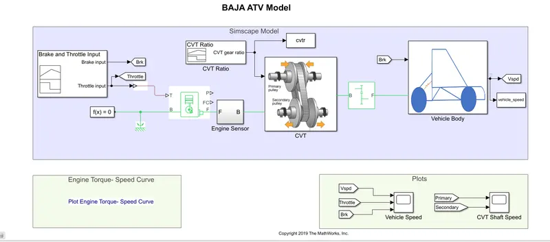
This is the proposed model of an All Terrain Vehicle (ATV)designed for BAJA with a continous variable transmission(CVT).
There are 3 subsystems in the model for Enigne,CVT and for the Vehicle body.
outputs from different blocks are collected and are plotted and the performances are analysed.
ENGINE:
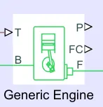
A Generic Engine is used which is the most simple type of spark lgnition Engine in simulink and can be categorised into petrol and diesel variants.
a subsystem is present which has the sensors to capture the movement of the engine. the engine is parametrised on tabulated torque data.
Represents a system-level model of spark-ignition and diesel engines suitable for use at initial stages of modeling when only the basic parameters are available.
Optional idle speed and red line controllers are included.
ENGINE SENSOR:
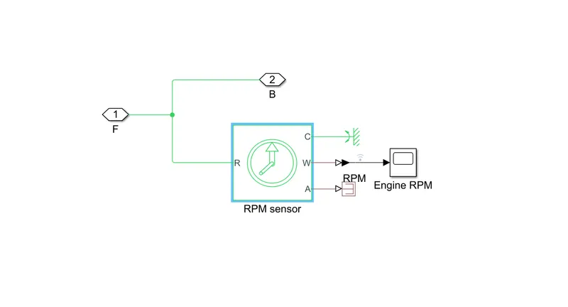
This sub-system consist of an Ideal Rotational Motion Sensor block which receives the input from the crank shaft port.
This block was used to measure the angular velocity of the engine.
CVT :
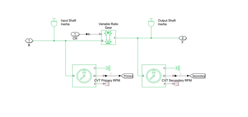
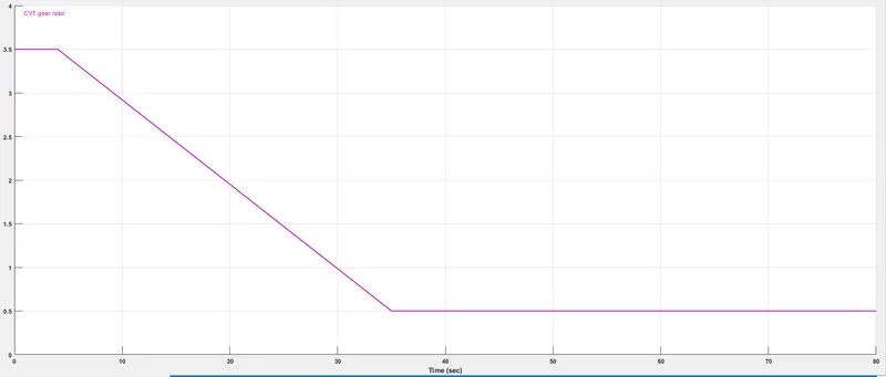
This sub system consist of a variable gear system.
A CVT is used for transmission which is degined using a variable gear inside a subsystem and the gear ratio is changed using the torque output that is achieved in a closed loop system.
VEHICLE BODY:
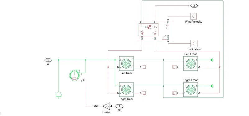
The vehicle body is designed with the basic blocks of brakes and wheels, no parameters are changed and are kept to default that can be changes according to the user.
basic blocks of wheels are used and are conected to the variable torque provided by the CVT.
the output velocity is obtained and the results.
SIGNAL BUILDER:
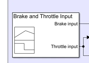
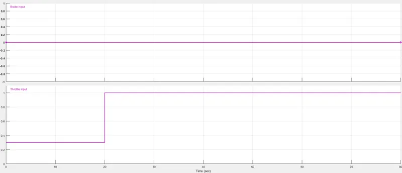
Initially a signal builder block was used to generate the input signals.
These two signals include brake and throttle inputs.
The signal builder briefing was attached below.
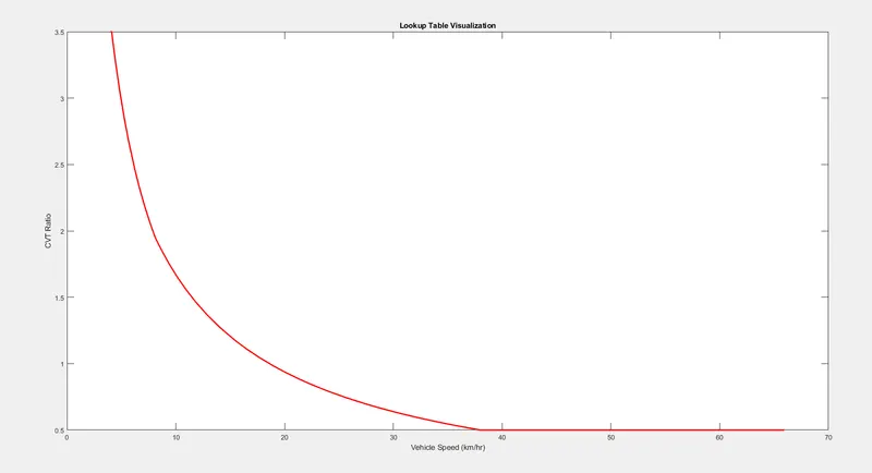
CVT Ratio :
RESULTS:
The simulation had a runtime of 200s.
The plot obtained from the primary scope block containig velocity, brake and throttle inputs was attached below.
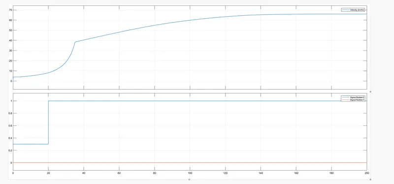
this plot clearly depicts that the vehicle speed increases as the throttle increases.
initially when the throttle was constant, the speed was rising slowly and once the throttle attains the maximum value the speed was also increased and the continued at constant speed.
the plot obtained from the secondary scope block containig primary and secondat RPM input was attached below.
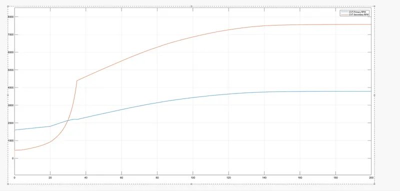
This plot was actually obtained from the RPM results from the ctv sub system.
the blue curve represents the primary RPM and the red curve represents the secondary RPM.
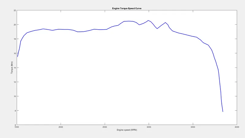
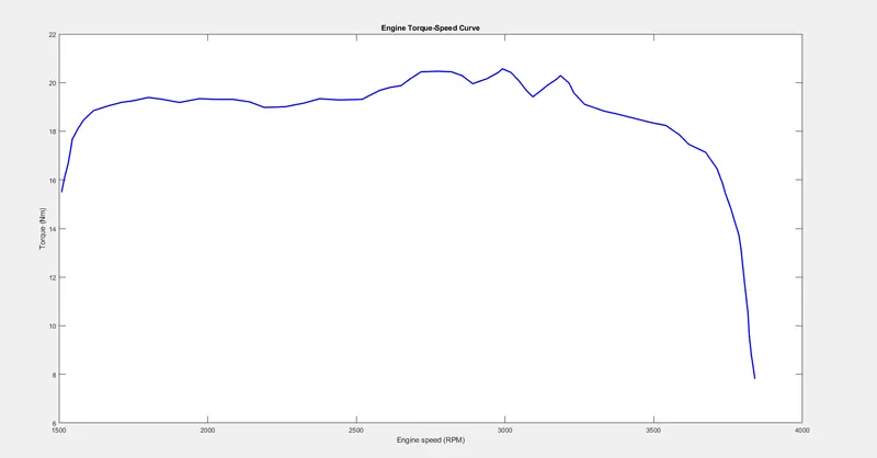
this plot below was obtained by clicking on the plot link in the model.
it depicts the relation b/w the torque and speed of the engine.
it was observed that at initial speed the torque was more. as the speed increases,the torque also increases upto certain speed.
torque is inversely propotional to the speed and thus at high speeds the torque was very less.
at high speeds there is no need for torque to move the vehicle.
MODEL WITH DASHBOARD:
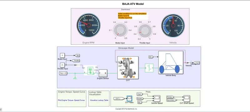
In this model we have a dashboard which contains knobs to control the inputs.
in this case,the inputs Throttle and Brake are not provided using signal builder. A knob is provided to control both the parameters in real-time for the user.
VEHICLE SPEED OUTPUT:
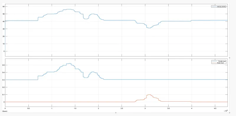
It can be observed from the graph that the velocity of the vehicle increases from 0 to 56kmph when throttle value is 0.5 and brake input is 0.
once the braking value increases from 0 to 0.1 the velocity of vehicle decreases to constant throttle value and velocity value.
CVT SHAFT RPM:
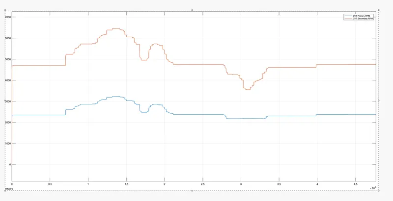
This graph indicates the CVTprimary RPM AND CVT secondary RPM.
the primary RPM is the input and secondary RPM is the output.
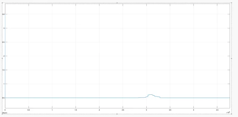
CVT RATIO:
LOOKUP TABLE VISUALISATION:
ENGINE TORQUE-SPEED CURVE:
CONCLUSION:
The successfully analysed different models of BAJA AVT WITH CVT outputs.