Week-6 Challenge: EV Drivetrain
EV DRIVETRAIN
1. Types of Power Converters that are employed in electric and hybrid electric vehicles.
Ans.: EVs use electrical energy to drive the vehicle and for the electrical appliances in the vehicle to function. According to International Electro-Technical Commission's Technical Committee (IETCTC), if the vehicle uses 2 or more energy sources, a storage device and a converter to drive the vehicle, then it's called Hybrid Electric Vehicle (HEV) as long as at least one source is providing electrical energy.
EVs are classified into different types according to the combination of sources -
-
Battery Electric Vehicle (BEV) (Battery alone works as a source.)
-
Fuel Cell Electric Vehicle (FCEV) (Fuel Cell and Battery works as source)
-
Hybrid Electric Vehicle (HEV) (Battery and ICE works as source)
Battery Electric Vehicle (BEV):
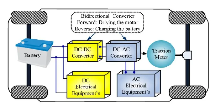
In BEV, the unidirectional Step-up DC-DC Converter is adopted to boost the voltage as per the demand of the propelling system and the electrical load. The low voltage/power rated equipment, such as the mobile charger receives supply from the battery.
The DC Voltage of the battery is transferred to a high voltage DC Bus through Step-up DC-DC Converter. The high voltage DC Bus supply power to higher voltage rated equipment such as Projector Lamps.
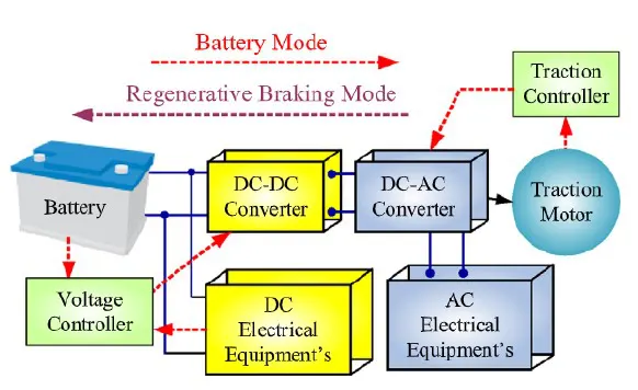
The function of the DC-AC Inverter is to convert the DC into a variable (voltage and frequency) 3-phase AC to drive the AC Motor. To drive the vehicle and other electronic equipment, the DC power supply from the battery is used as fuel. The voltage controller controls the DC-DC converter to maintain the charging level of the battery at its maximum and minimum limit.
a) Typical Structure of BEV.
b) Control Scheme Operating Modes of BEV.
Fuel Cell Electric Vehicle (FCEV):
In FCEV, the electric energy is generated from the battery and fuel cell. The main goal of FCEVs is to convert electrical energy from fuel cells to usable power for various loads of the vehicle by using an efficient method to improve the efficiency and performance of the vehicle.
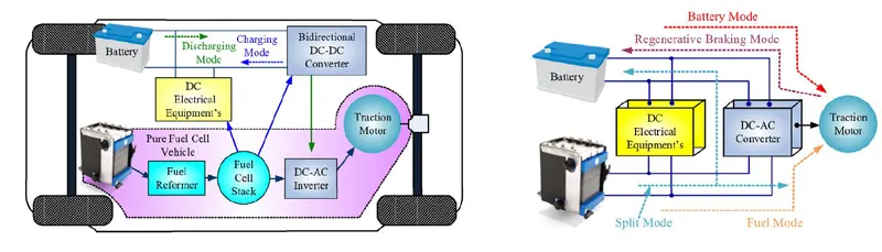
Low voltage DC requirements, such as mobile chargers, auto starters receive power directly from a battery or fuel cell. For motor drive and high voltage applications, the low voltage is stepped-up to 300 V using a Step-ep DC-DC Converter.
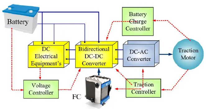
In FCEV electrical system, a Bi-Directional DC-DC Power Converter plays a key role in controlling the energy flow from the fuel cell to a traction motor during motor mode and from the motor to the battery during regenerative braking mode in Hybrid FCEV. It controls the energy flow with the help of traction and voltage controllers.
The function of the DC-AC Inverter is to convert the DC into a variable (voltage and frequency) 3-phase AC to drive the AC Motor.
a) Structure and Operating Modes of FCEV
b) Control Scheme of FCEV
Hybrid Electric Vehicle (HEV):
The hybrid electric vehicle is a combination of an ICE vehicle and a BEV. The ICE provides the necessary propelling power to drive the train of vehicles. By regenerative mechanism, the lost energy during the braking mechanism is stored in the battery to increase the efficiency and economy of the vehicle.
There are 2 types of hybrid electric vehicles, namely
-
Series Hybrid Electric Vehicles (SHEV)
-
Parallel Hybrid Electric Vehicles (PHEV).
And to improve power, performance and fuel economy, a 3rd
-
Series-Parallel Hybrid Electric Vehicle (SPHEV) was introduced by combining the features of SHEV and PHEV.
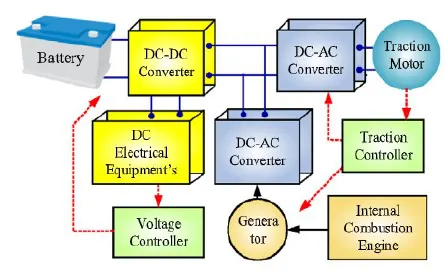
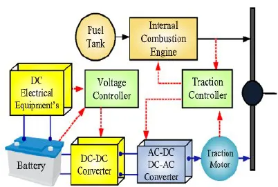
The power electronic converters maintain and control the flow of energy from the battery or ICE to the traction motor and the traction motor to the battery with the help of a voltage and traction controller. The low voltage from the battery is supplied to the low voltage rated DC equipment such as mobile chargers and auto start-up.
The DC-DC Rectifier adopted converts the variable AC to a constant DC voltage during the regenerative mode. In battery mode, high DC voltage is converted into variable AC quantities to maintain the required torque and speed.
-
Series Hybrid Electric Vehicles (SHEV):
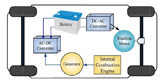
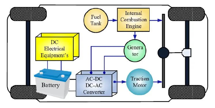
The mechanical energy is converted from ICE to electrical form by using a Generator. The generated AC power is converted into the DC form to charge the battery by using an AC-DC Rectifier.
In SHEV, the ICE is not directly connected to the traction motor to drive the train. In between the ICE and the traction motor, the battery is the intermediate unit and the primary source of power to drive the train.
The ICE runs at the optimal speed to drive the generator and charge the battery. When the State of Charge (SOC) of the battery is minimized, the ICE starts to charge the battery. As the SOC reached its maximum level of around 65% - 70%, the ICE stops charging the battery.
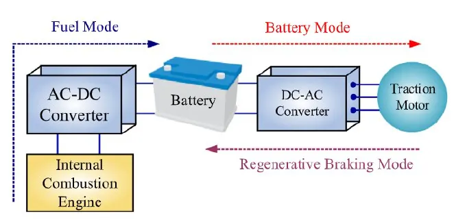
Three operating modes are observed in SHEV -
-
In Fuel mode, ICE is utilized to charge the battery according to the SOC of the battery.
-
In Battery mode, the propelling power is gained from the battery.
-
In Regenerative mode, the traction motor acts as a source during the braking operations to charge the battery.
a) Typical Structure of SHEV
b) Operating Modes of SHEV
-
Parallel Hybrid Electric Vehicles (PHEV):
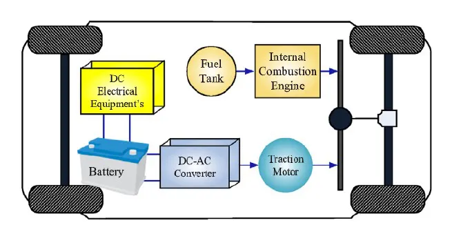
In PHEV, both the ICE and the electrical motor are coupled to the driving shaft via two clutches. The ICE is directly connected to the mechanical shaft of the drive train to propel the vehicle. As there are no intermediate conversion stages between ICE and the drive train, the efficiency of PHEV is greater when compared to SHEV. PHEV is a more viable solution for the long-distance range due to no intermediate conversion stages. Hence, it's more fuel-efficient.
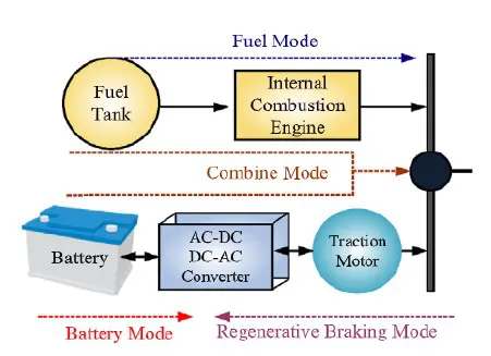
There are 3 different ways to utilize the ICE and Battery in PHEV -
-
Motor mode – Battery is utilized to power the train, which is a viable solution for lower speeds.
-
Fuel mode – The ICE runs at an optimal speed to drive the train at high speed.
-
Regenerative mode – During braking or deceleration operations, the traction motor acts as a generator to charge the battery in regenerative mode.
In PHEV, the lowest DC Voltage is boosted by a bi-directional DC-DC Converter to feed the high voltage DC bus. The function of the 3-phase inverter is to convert the constant DC voltage into variable AC voltage and frequency to maintain the torque and speed of the traction motor.
a) Typical structure of PHEV
b) Operating mode of PHEV
Series-Parallel Hybrid Electric Vehicle (SPHEV):
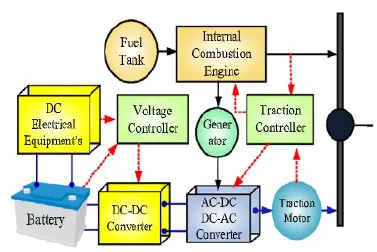
The SPHEV configuration incorporated the features of SHEV and PHEV. IN SPHEV, the generator is introduced in between the ICE and the battery to charge the battery as compared to PHEV and ICE is directly connected to the mechanical shaft to drive the vehicle as compared to SHEV.
There are 5 different ways to utilize the ICE and the Battery to propel the vehicle and other electrical equipment function -
-
Fuel Mode – ICE works to drive the vehicle.
-
Battery Mode – The excess power is utilized to charge the battery.
-
Split Mode – The ICE transfers the power to the traction motor and the excess power is utilized to charge the battery.
-
Combine Mode – Both the ICE and the Battery provides power to the traction motor.
-
Regenerative Mode – During the braking and deceleration operations, the traction motor acts as a generator and supplies the power to the battery.
The most adopted strategy for effective utilization of battery and ICE in SPHEV is that the battery is utilized to start operation and propel at low speed after the ICE works alone to drive at high speed, which increases the vehicle's fuel efficiency. When acceleration is needed the battery mode is in an active state to give extra power along with the ICE.
a) Typical structure of SPHEV
b) Working mode of SPHEV

Control Schemes of SHEV Control Schemes of PHEV
Control Schemes of SPHEV
Plug-in Hybrid Electric Vehicle (P-EV):
The PEV is a type of HEV in which the battery is charged from an external source. The ICE is not sufficient to convert the fuel energy to mechanical energy to drive the shaft. Most of the energy is lost as heat during conversion.
Moreover, the ICE emits greenhouse gases as a by-product. To overcome the drawback of ICE, ICE is replaced by a battery. It works on the electrical supply, where the battery is charged at the battery charging station.
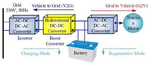
PEV works in 2 operating modes -
-
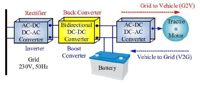
Grid to Vehicle – Battery charges from the grid.
-
Vehicle to Grid – Battery injects power to the grid.
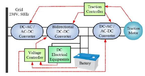
The Rectifier unit is utilized to convert the 3 – phase or single-phase power to constant DC power to charge the battery through a Step-down DC-DC Converter. For maintaining the speed and the torque of the traction motor, traction control is adopted.
The Voltage Controller controls the power flow from the battery in/out directions. In PEV, the Bi-Directional DC-DC Converter plays a vital role in controlling the bi-directional flow of energy. It operates in Step-up mode during the V2G mode and acts as Step-down Converter in G2V mode.
The operating mode is of the bi-directional DC-DC Converter is controlled by the voltage controller.
a) Typical structure of PEV
b) Operating mode of PEV
c) Control Scheme of PEV
2. An Electric Vehicle's powertrain with a 72V battery pack is shown in the diagram below. The duty ratio for acceleration operation is 'd1' and for the braking operation the duty ratio is 'd2'.
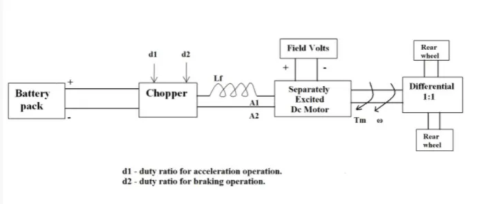
The other parameters of the electric vehicle are given below,
Motor and Controller Parameters:
Rated Armature voltage= 72 V
Rated armature current= 400 A
Ra= 0.5Ω, KΦ= 0.7 Volt second
Chopper Switching frequency= 400 Hz
The vehicle speed-torque characteristics are given by the below equation
Tv = 24.7 + (0.0051).ω2
What is EV steady-state speed if the duty cycle is 70%?
Ans.
Tv = 24.7 + (0.0051).ω2 ... Eq. 1
Duty cycle = 70% = 0.7
Actual voltage = 0.7 * 72
= 50.4 V
Torque eqn. for motor,
T = [V * KΦ / Ra] - [(KΦ)2 / Ra] . ω
= [50.4 * 0.7 / 0.5] – [(0.7)2 / 0.5] . ω
= 70.56 – 0.98.ω ... Eq. 2
Now, comparing the vehicle torque and motor torque, (Eq. 1 and Eq. 2 respectively), we get
=> 24.7 + (0.0051).ω2 = 70.56 – 0.98.ω
=> 0.0051ω2 + 0.98.ω – 45.86 = 0
Solving the quadratic equation, we get
ω = 38.915 rad/sec
& ω = - 231.072 rad/sec
We'll only consider the positive value of ω (Steady state speed).
=> ω = 38.915 rad/sec = 371.6 ~ 370 rpm
Therefore, the steady-state speed of the EV at 70% duty cycle is 38.915 rad/sec or 370 rpm.
MATLAB Code:
%% MATLAB program to find the steady-state speed of EV
clear all
close all
clc

%% Input or given parameters
volt_Arm = 72;          % Given armature voltage in V
curr_Arm = 400;         % Given armature current in Amp
resis_Arm = 0.5;        % Given armature resistance in Ohm
motor_Const = 0.7;      % Given motor constantm, KΦ
duty_cycle = 70;        % Given duty cycle in %.

%% Calculations and Equation - 1 solving
volt_actual = (duty_cycle / 100) * volt_Arm;

% Creating scalar variables for calculating Motor Torque(Tm)
% and Angular speed(w) of the motor.
syms ('motor_torq', 'ang_speed');

% Equating the motor torque value to equation 1 and then calculating it with
% the values of actual voltage, motor constant, angular speed (w), and
% armature resistance.
part1 = (volt_actual * motor_Const)/resis_Arm;
part2 = ((motor_Const^2)/resis_Arm);

equation_1 = motor_torq == part1 - (part2).*ang_speed;

eq1_solution = solve (equation_1);

% Printing the solution of the above equation which was stored in eq1_solution
fprintf ("Equation 1 = %s\n", eq1_solution);

%% Calculations and Equation - 2 solving
equation_2 =  24.7 + (0.0051*(ang_speed.^2));

% Creating scalar variables for calculating Angular speed(w) of the motor.
syms ('ang_speed');

% Equating the solution of eq.1 and eq.2
EQN = eq1_solution == equation_2 ;
eq2_solution = vpasolve (EQN, [ang_speed]);
eq2_solution_2 = solve (EQN, [ang_speed]);

% Printing the solution of the above equation which was stored in eq2_solution
fprintf ("Equation 2 = %s, \n\t\t\t%s \n", eq2_solution, eq2_solution_2);  %
%fprintf ("Equation 2 = %s\n", eq2_solution_2);

% Converting the angular speed from rad/sec to RPM
s2rpm = (eq2_solution(2)*60)./(2*3.14);

% Printing the final result
fprintf ("\nEV steady state speed, if duty cycle is 70 perc");
fprintf ("\n\tin rad/sec -> %0.2f rad/sec", eq2_solution(2));
fprintf ("\n\tin RPM -> %0.2f RPM\n", s2rpm); 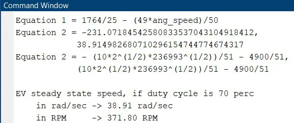
Code Explanation:
-
Initialized given data for armature voltage, armature current, armature resistance, duty cycle and the motor constant.
-
Calculated the actual voltage from duty cycle and armature voltage.
-
Created a scalar variable using “syms” for calculating the motor torque and motor angular speed.
-
Divided this equation T = [V * KΦ / Ra] - [(KΦ)2 / Ra] . ω into 2 parts
-
Part – 1 = [V * KΦ / Ra]
-
Part – 2 = [(KΦ)2 / Ra]
-
-
Solved the equation using “solve” and stored the solution of the equation in eq1_solution and printed the result using fprintf.
-
Initialized the 2nd given equation and again created a scalar variable using “syms”.
-
Now, equated the solution of equation 1 and equation 2 and stored it in EQN.
-
Then, got the solution of the 2nd equation using “vpasolve” and “solve”.
-
Printing the result of the solutions of the equations.
-
Converting the result, which we got in rad/sec, to RPM and printing the final result of the EV Steady State Speed in rad/sec and RPM.
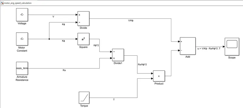
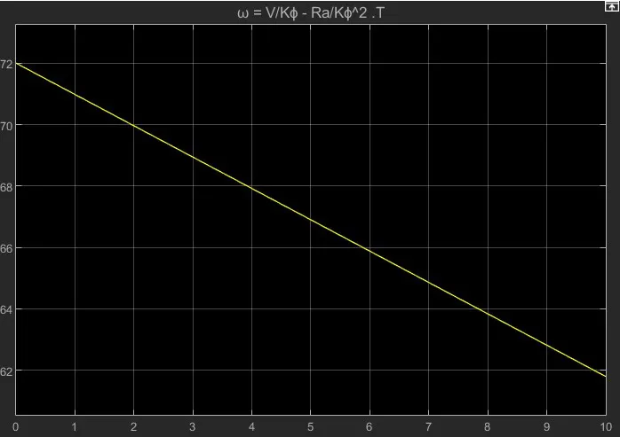
3. Mathematical model of a DC Motor for the below equation using Simulink.
ω = V/Kϕ - Ra/Kϕ^2 .T
Simulink model:
Output:
4. Explain in brief about author’s perspective for Induction Versus DC brushless motors by Wally
Ans.
Wally Rippel has long advocated for electric automobiles. Prior to joining Tesla Motors, he worked as an engineer at AeroVironment, where he assisted in the development of the EV1 for General Motors and was featured in the documentary film Who Killed the Electric Car? Wally has also worked on electric car battery research at the Jet Propulsion Laboratory, among other things. As a Caltech undergraduate student in 1968, he created an electric automobile and defeated MIT in the Great Transcontinental Electric Car Race.
One Size Does Not Fit All:
Engines are not all identical in the dreadful world of gas-powered cars. Flat-heads, Hemis, straight, opposing, and V designs are available. And so forth. Years ago, you'd think someone would have worked out which was better. That would have eliminated all options, leaving just the greatest engine type in production. No, it does not. There is no single optimum engine type; rather, numerous types of engines are available to meet individual needs, such as price and performance. This is also true for driving an electric car.
There were lead-acid batteries, DC brush motors, and contactor controllers back when the author had hair on his head and carried a slide rule. None of those exists now. Lead has been replaced by lithium, and direct current (DC) has been replaced by either DC brushless motor or induction motor. Meanwhile, contactors have given way to modulating inverters. So, will each of these elements become outdated in the near future, or is it feasible that some «stability» is on the horizon? It is difficult to foresee the future without a reliable crystal ball. My expectation is that both induction and brushless motors will continue to "battle it out" for many years to come. Each will have ardent supporters as well as adversaries from the religious community.
So, what are these two technologies? How do they work? What differentiates them? And what do they have in common?
Let’s start with DC brushless motors.
Brushless motors have rotors that contain two or more permanent magnets that create a direct current magnetic field. This magnetic field then enters the stator core and interacts with currents flowing through the windings to generate a torque interaction between the rotor and stator. As the rotor rotates, the amplitude and polarity of the stator currents must be continually adjusted – and in exactly the correct way – so that the torque remains constant and the conversion of electrical to mechanical energy is as efficient as possible. An inverter is a device that controls the current. Brushless motors are ineffective without it.
Let us now turn our attention to induction motor drives. Nikola Tesla created a precursor of the three-phase induction motor before 1889. Surprisingly, the stators for the three-phase induction motors and the DC brushless motors are almost similar. Both feature three sets of "distributed windings" put into the stator core. The rotor is the primary distinction between the two devices.
The induction rotor, unlike the DC brushless rotor, lacks magnets and instead consists of stacked steel laminations with buried peripheral conductors that form a shorted structure. Currents in the stator windings generate a revolving magnetic field that enters the rotor. In turn, the frequency of this magnetic field as «seen» by the rotor is equal to the difference between the applied electrical frequency and the rotor's rotating frequency. As a result, an induced voltage occurs across the shorted structure that is proportional to the rotor speed difference and electrical frequency. In reaction to this voltage, currents inside the rotor conductors are created that are approximately proportional to the voltage, resulting in the speed differential. Finally, these currents interact with the original magnetic field to produce forces – a component of which is the desired rotor torque.
When a three-phase induction motor is connected to utility-type three-phase electricity, torque is generated right away, and the motor may start under load. There is no need for an inverter. The fundamental reason for induction motors' popularity is that they are immediately compatible with regular utility power. When directly connected to fixed frequency utility power, a brushless DC motor provides no starting torque. They truly need the help of an inverter whose «phase» is kept in sync with the rotor's angular location.
While 3-phase induction motors provide a lot of advantages, they also have a lot of drawbacks. They can't run on DC; AC is required. Line frequency is proportional to shaft speed. As a result, they are constant speed machines when powered by utility electricity. Finally, when compared to DC type machines, they have reduced beginning torque and running peak torque capabilities when operated off utility power.
With the addition of an inverter, a motor may be powered by a battery or other DC source, and variable speed can be achieved simply by modifying the inverter frequency. However, as compared to DC motors, torque performance is still lacking. When feedback loops are included to ensure that the inverter delivers the precise frequency that the motor desires, the induction motor may now compete with DC and DC brushless motors in automotive applications.
Brushless or Induction?
Except for one, all-electric cars of the 1990s were powered by DC brushless motors. Without exception, all hybrids nowadays are powered by DC brushless drives. The GM EV-1, the AC Propulsion vehicles, including the zero, and the Tesla Roadster are the only cars that have used induction drives.
Motors with comparable stators are used in both DC brushless and induction drives. Three-phase modulating inverters are used in both drives. The rotors and inverter controls are the only modifications. The only control variations with digital controllers are in the control code.
One of the most significant distinctions is that the DC brushless motor generates significantly less rotor heat. This drive has a simpler rotor cooling system and a greater peak point efficiency. The DC brushless motor can also run at unity power factor, whereas the induction motor's greatest power factor is around 85%. This means that a DC brushless motor's peak point energy efficiency will normally be a few percentage points greater than an induction motor.
The intensity of the magnetic field created by the permanent magnets in an ideal brushless motor would be customizable. When maximal torque is required, particularly at low speeds, the magnetic field strength should be maximised, allowing inverter and motor currents to be kept to a minimum. As a result, I2R losses are minimised, and efficiency is maximised. When torque levels are low, the magnetic field should be lowered as well, reducing eddy and hysteresis losses caused by the magnetic field. The magnetic field should ideally be set so that the total of the eddy, hysteresis, and I2 losses is as small as possible. Unfortunately, permanent magnets make it difficult to change the magnetic field.
Induction machines, on the other hand, have no magnets and their magnetic fields may be adjusted since the magnetic field is proportional to V/f. This implies that during low loads, the inverter may lower the voltage, reducing magnetic losses and increasing efficiency. Thus, when used with a smart inverter, an induction motor has an advantage over a DC brushless motor in that magnetic and conduction losses may be swapped to improve efficiency. As performance improves, this advantage becomes more crucial. When using a DC brushless motor, the magnetic losses rise proportionately as the machine size expands, and part-load efficiency decreases. With induction, losses do not always increase as machine size increases. When high performance is required, induction motors may be the best option; peak efficiency will be somewhat lower than DC brushless, but average efficiency may be higher.
Permanent magnets are costly, costing around $50 per kg. Permanent magnet rotors are extremely difficult to handle since anything ferromagnetic that comes close to them generates enormous forces. As a result, induction motors are expected to maintain a cost advantage over PM motors. Inverter ratings and prices look to be lower, especially for high-performance drives, due to induction motors' field weakening capabilities. When de-excited, spinning induction motors create little or no voltage, making them easier to safeguard.
Induction motors are harder to manage. The laws governing control are more complicated and difficult to comprehend. Induction motor is more difficult to provide stability across the whole torque-speed range and over temperature than DC brushless motor. This indicates that there will be additional development expenditures, but there will be minimal or no recurrent costs.
Still No Winner
Induction motors will likely continue to dominate the high-performance pure electrics market, while DC brushless motors will likely continue to dominate the hybrid and impending plug-in hybrid industries. What will happen when hybrids grow more electrically intensive and their performance levels improve, is the question. Because so much of the technology is shared across the two motor drives, it's possible that induction motor and DC brushless motor may coexist in the future golden age of hybrid and electric automobiles.
References:
Links: