Week-6 Challenge: EV Drivetrain
OBJECTIVE:
- To discuss various types of Power Converter circuits employed in Electric and Hybrid Electric vehicles.
- To calculate the steady state speed at a duty cycle of 70% for the given data:
-
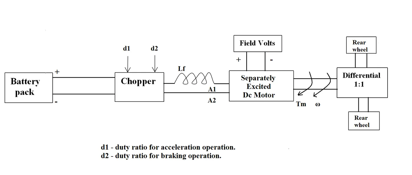
An Electric Vehicle's powertrain with 72V battery pack is shown in the diagram below. The duty ratio for acceleration operation is 'd1' and for the braking operation the duty ratio is 'd2'.
The other parameters of the electric vehicle are given below,
Motor and Controller Parameters:
Rated Armature voltage= 72 V
Rated armature current= 400 A
Ra= 0.5Ω, KΦ= 0.7 Volt second
Chopper Switching frequency= 400 Hz
The vehicle speed-torque characteristics are given by the equation below:

-
- To develop a mathematical model of a DC Motor for the equation below using Simulink.
- `omega = V_t/(Kphi) - (R_a)/(Kphi)^2*T_v`
- To read the blog on the below topic and explain the author's perspective:
SOLUTION:
OBJECTIVE - 1:
DIFFERENT TYPES OF POWER CONVERTERS EMPLOYED IN EVs AND HEVs:
- Power electronic converters are used everywhere in normal daily routines at home, commercial workplaces or in an industrial environment.
- Due to the high-power handling with higher efficiencies, these converters become an integral part of industrial electric drives, high electric power supplies, electric traction systems and automobile control equipment.
- There are different types of power electronic converters used for performing different functions (such as inversion, rectification, etc.) which are rated from a few milliwatts to a few thousand watts. Let us look at these converters in detail.
- Power electronic technology deals with processing and controlling the flow of electrical energy in order to supply voltages and currents in a form that optimally suited for end user’s requirements.
- A power electronic converter uses power electronic components such as SCRs, TRIACs, IGBTs, etc. to control and convert the electric power. The main aim of the converter is to produce conditioning power with respect to a certain application.
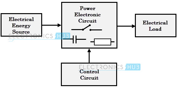
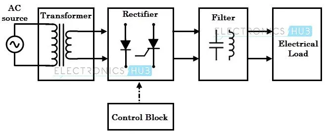
- The block diagram of a power electronic converter is shown in figure above. It consists of an electrical energy source, power electronic circuit, a control circuit and an electric load. This converter changes from one form of electrical energy to another form of electrical energy.
- The power electronic circuit consists of both the power part and the control part. The power part transfers the energy from source to load and it consists of power electronic switches (SCR or TRIAC), transformers, electric choke, capacitors, fuses and sometimes resistors.
- The control circuit or block regulates the elements in the power part of the converter. This block is built with a complex low power electronic circuit that consists of either analog or digital circuit assembly.
- Power electronic converters perform various basic power conversion functions. This converter is a single power conversion stage that can perform any of the functions in AC and DC power conversion systems.
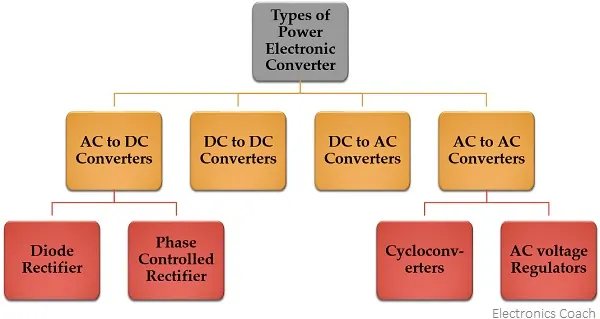
- Depending on the type of function performed, power electronic converters are categorized into the following types.
- AC to DC = Rectifier: It converts AC to unipolar (DC) current
- DC to AC = Inverter: It converts DC to AC of desired frequency and voltage
- DC to DC = Chopper: It converts constant to variable DC or variable DC to constant DC
- AC to AC = Cycloconverter, Matrix converter: It converts AC of desired frequency and/or desired voltage magnitude from a line AC supply.
- These types of power electronic converters may be found in a wide variety of applications such as switch mode power supplies (SMPS), electrical machine control, energy storage systems, lighting drives, active power filters, power generation and distribution, renewable energy conversion, flexible AC transmission and embedded technology.
AC TO DC CONVERTERS:
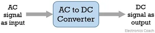
- A type of converter that changes input AC signal into a DC is known as AC to DC converter. We have already learned in basic electronics that the devices that convert the AC signal into DC signal are known as rectifiers.
AC to DC Converter is further classified as:
- Diode Rectifiers: This rectifier circuit changes applied ac input voltage into a fixed dc voltage. Either a single-phase or three-phase ac signal is applied at the input. These are mainly used in electric traction and in electrochemical processes like electroplating along with in battery charging and power supply. These are also used in welding and UPS related services.
- Phase Controlled Rectifiers: Unlike diode rectifiers, phase-controlled rectifiers are designed to convert a fixed value of ac signal voltage into a variable dc voltage. Here line voltage operates the rectifier hence these are sometimes known as line commutated ac to dc converters. Similar to diode rectifiers, here also the applied ac signal can be a single-phase or three-phase ac signal. Its major applications are in dc drives, HVDC systems, compensators, metallurgical and chemical industries as well as in excitation systems for synchronous machines.
DC TO DC CONVERTERS:
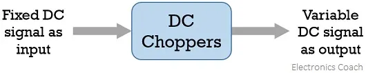
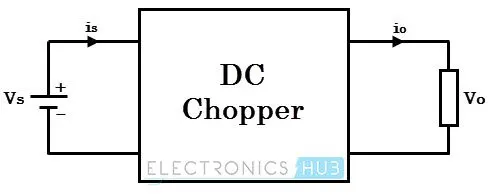
- The converters that convert the dc signal of fixed frequency present at the input into a variable dc signal at the output are also known as choppers. Here the achieved output dc voltage may have a different amplitude than the source voltage. Generally, power transistors, MOSFETs, and thyristors are the semiconductor devices used for their fabrication. The output is controlled by a low power signal that controls these semiconductor devices from a control unit.
- Here forced commutation is required to turn off the semiconductor device. Generally, in low power circuits power transistors are used while in high power circuits thyristors are used.
- Choppers are classified on the basis of the type of commutation applied to them and on the basis of the direction of power flow. Some major uses of choppers are in dc drives, SMPS, subway cars, electric traction, trolley trucks, vehicles powered by battery, etc.
DC TO AC CONVERTERS:
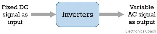
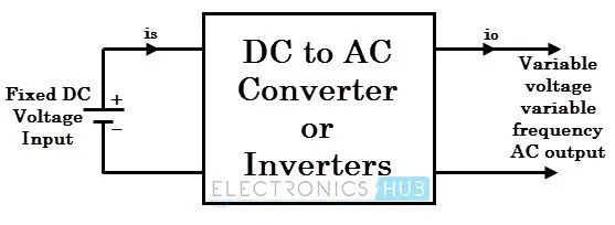
- The devices that are designed to convert the dc signal into ac signal are known as inverters. The applied input is a fixed dc voltage that can be obtained from batteries but the output obtained is variable ac voltage. The voltage and frequency of the signal obtained are of variable nature. Here the semiconductor device i.e., the thyristor is turned off by using either line, load, or forced commutation.
- Thus, it can be said that by the use of inverters, a fixed dc voltage is changed into an ac voltage of variable frequency. Generally, the semiconductor devices used for its fabrication are power transistors, MOSFETs, IGBT, GTO, thyristors, etc.
- Inverters mainly find applications in induction motor and synchronous motor drives along with UPS, aircraft, and space power supplies. In high voltage dc transmission system, induction heating supplies as well as low power systems of mobile nature like flashlight discharge system in photography camera to very high-power industrial system.
- Like choppers, in inverters conventional thyristors are also used in high power applications and power transistors are used in low power applications.
AC TO AC CONVERTERS:
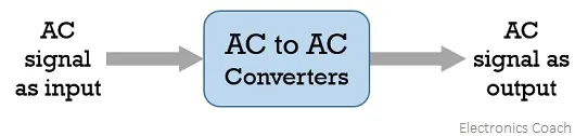
- An ac to ac converter is designed to change the ac signal of fixed frequency into a variable ac output voltage.
There are two classifications of ac to ac converters which are as follows:
- Cycloconverters: A cycloconverter is a device used for changing ac supply of fixed voltage and single frequency into an ac output voltage of variable voltage as well as different frequency. However, here the obtained variable ac signal frequency is lower than the frequency of the applied ac input signal. It adopts single-stage conversion. Generally, line commutation is mostly used in cycloconverters, however forced or load commutated cycloconverters are also used in various applications.
- These mainly find applications in slow-speed large AC traction drives such as a rotary kiln, multi-MW ac motor drives, etc.
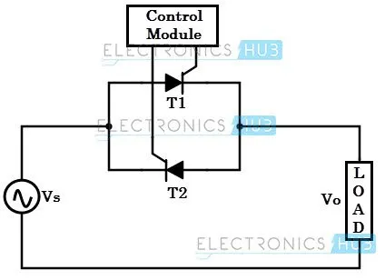
- AC Voltage Controllers (AC voltage regulators): The converters designed to change the applied ac signal of fixed voltage into a variable ac voltage signal of the same frequency as that of input. For the operation of these controllers, two thyristors in an antiparallel arrangement are used. Line commutation is used for turning off both the devices. It offers controlling the output voltage by changing the firing angle delay.
- The major applications of ac voltage controllers are in lighting control, electronic tap changers, speed control of large fans and pumps as well.
OBJECTIVE - 2:
TO CALCULATE STEADY STATE SPEED OF THE EV AT A DUTY CYCLE OF 70%:
- Given data:
- An Electric Vehicle's powertrain with 72V battery pack is shown in the diagram below. The duty ratio for acceleration operation is 'd1' and for the braking operation the duty ratio is 'd2'.
- Rated Armature Voltage = 72 V
- Rated Armature Current = 400 A
- Armature Resistance R_a = 0.5 ohm
- K*Phi = 0.7 Volt Second
- Chopper Switching Frequency = 400 Hz
- Duty Cycle = 70%
-
The vehicle speed-torque characteristics are given by the equation below:
- Let us consider the above Torque equation as equation 1.
- `T_v = 24.7 + (0.0051)omega^2`........................................................ (1)
- The relation between Speed and Torque is:
- `omega = V_t/(Kphi) - (R_a)/(Kphi)^2*T_v`
- Also,
- `T_v = (V_t*Kphi)/(R_a) - (Kphi)^2/(R_a)*omega`
- `V_t = V_s *`Duty Cycle
- V_t = 72 * 0.7 = 50.4 V
- Now Solving the Torque equation:
- `T_v = (50.4*0.7)/0.5 - (0.7)^2/0.5*omega`
- `T_v = 70.56 - 0.98*omega` ...............................................................(2)
- Equating both the equations we get:
- `24.7 + (0.0051)*omega^2 = 70.56 - 0.98*omega`
- `(0.0051)*omega^2 + 0.98*omega - 45.86 = 0` ..................................(3)
- The above equation is a Quadratic Equation and is in the form of ax^2 + by + c = 0.
- To find the solutions:
- D = b^2 - 4*a*c
- D = 0.98^2 - 4*0.0051*(-45.86)
- D = 0.9604 + 0.935544
- D = 1.895944
- `root_D = 1.377`
- `alpha = (-b + root_D)/(2*a)`
- alpha = (-0.98 + 1.377) / (2*0.0051)
- alpha = 38.92
- `beta = (-b - root_D) / (2*a)`
- beta = (-0.98 - 1.377) / (2*0.0051)
- beta = -231.07
- By solving the above equation we got speed as 38.92 rad/sec and -231.07 rad/sec.
- Since we know the duty cycle is 70% which implies that more amount of voltage is supplied to the motor by the battery and the vehicle is in accelerating condition so, we will consider the positive value of the speed that is 38.92.
- Therefore, the steady state speed of the vehicle at 70% duty cycle is 38.92 rad/sec.
OBJECTIVE - 3:
TO DEVELOPE THE MATHEMATICAL MODEL OF SPEED VS TORQUE CHARACTERISTICS OF A DC MOTOR USING SIMULINK:
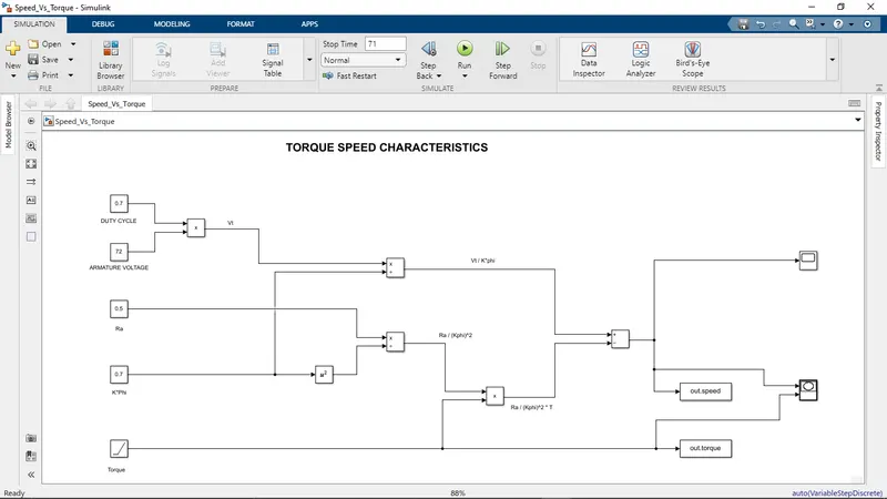
- The relation between Speed and Torque of a DC motor is:
- `omega = V_t/(Kphi) - (R_a)/(Kphi)^2*T_v`
- Creating a Simulink model to evaluate the above equation:
PLOTS:
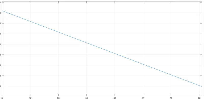
SCOPE: (SPEED VS TIME):
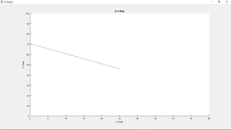
SPEED VS TORQUE GRAPH:
OBJECTIVE - 4:
INDUCTION VS DC BRUSHLESS MOTOR BY WALLY RIPPEL, TESLA
- In his blog he wants to discuss Electric vehicles and the Motors used in it.
- At the beginning he discussed that there is no best engine which will fit all the requirements and demands of all the people, rather there are different types of engines to suit personal requirements, such as price and performance. This is also true for electric vehicle drives.
- Then he discusses how different technologies are getting replaced by the upcoming new technologies like Lead has been replaced by lithium and DC by either DC brushless or induction and starts discussing the brushless DC motor and Induction motor.
- With brushless machines, the rotor includes two or more permanent magnets that generate a DC magnetic field (as seen from the vantage point of the rotor). In turn, this magnetic field enters the stator core (a core made up of thin, stacked laminations) and interacts with currents flowing within the windings to produce a torque interaction between the rotor and stator. As the rotor rotates, it is necessary that the magnitude and polarity of the stator currents be continuously varied – and in just the right way - such that the torque remains constant and the conversion of electrical to mechanical energy is optimally efficient. The device that provides this current control is called an inverter. Without it, brushless motors are useless motors.
- Unlike the DC brushless rotor, the induction rotor has no magnets – just stacked steel laminations with buried peripheral conductors that form a “shorted structure.” Currents flowing in the stator windings produce a rotating magnetic field that enters the rotor. In turn, the frequency of this magnetic field as “seen” by the rotor is equal to the difference between the applied electrical frequency and the rotational “frequency” of the rotor itself. Accordingly, an induced voltage exists across the shorted structure that is proportionate to this speed difference between the rotor and electrical frequency. In response to this voltage, currents are produced within the rotor conductors that are approximately proportionate to the voltage, hence the speed difference. Finally, these currents interact with the original magnetic field to produce forces – a component of which is the desired rotor torque.
- When a 3-phase induction motor is connected to utility type 3-phase power, torque is produced at the outset; the motor has the ability to start under load. No inverter is needed. (Were an inverter needed, Tesla’s invention would have been useless until sometime in the 1960s.) The fact that induction motors are directly compatible with conventional utility power is the main reason for their success. In contrast, a brushless DC motor produces no starting torque when directly connected to fixed frequency utility power. They really need the aid of an inverter whose “phase” is maintained in step with the angular position of the rotor.
- While 3-phase induction motors have great utility, they also have some severe limitations. They cannot operate from DC; AC is a must. Shaft speed is proportionate to line frequency. Hence, when used with utility power, they are constant speed machines. Finally, when operated from utility power, they have limited starting torque and somewhat limited running peak torque capabilities, when compared to DC type machines.
- Add an inverter (without any feedback control) and it becomes possible to power an induction machine from a battery or other DC source; variable speed also becomes possible simply by adjusting the inverter frequency. Still, torque performance is low compared with DC machines. Add some feedback loops such that the inverter produces the exact frequency that the motor “desires,” and the induction motor is now capable of competing with DC and DC brushless for vehicle applications.
- Both DC brushless and induction drives use motors having similar stators. Both drives use 3-phase modulating inverters. The only differences are the rotors and the inverter controls. And with digital controllers, the only control differences are with control code. (DC brushless drives require an absolute position sensor, while induction drives require only a speed sensor; these differences are relatively small.)
- One of the main differences is that much less rotor heat is generated with the DC brushless drive. Rotor cooling is easier and peak point efficiency is generally higher for this drive. The DC brushless drive can also operate at unity power factor, whereas the best power factor for the induction drive is about 85 percent. This means that the peak point energy efficiency for a DC brushless drive will typically be a few percentage points higher than for an induction drive.
- In an ideal brushless drive, the strength of the magnetic field produced by the permanent magnets would be adjustable. When maximum torque is required, especially at low speeds, the magnetic field strength (B) should be maximum – so that inverter and motor currents are maintained at their lowest possible values. This minimizes the I² R (current² resistance) losses and thereby optimizes efficiency. Likewise, when torque levels are low, the B field should be reduced such that eddy and hysteresis losses due to B are also reduced. Ideally, B should be adjusted such that the sum of the eddy, hysteresis, and I² losses is minimized. Unfortunately, there is no easy way of changing B with permanent magnets.
- In contrast, induction machines have no magnets and B fields are “adjustable,” since B is proportionate to V/f (voltage to frequency). This means that at light loads the inverter can reduce voltage such that magnetic losses are reduced and efficiency is maximized. Thus, the induction machine when operated with a smart inverter has an advantage over a DC brushless machine – magnetic and conduction losses can be traded such that efficiency is optimized. This advantage becomes increasingly important as performance is increased. With DC brushless, as machine size grows, the magnetic losses increase proportionately and part load efficiency drops. With induction, as machine size grows, losses do not necessarily grow. Thus, induction drives may be the favored approach where high-performance is desired; peak efficiency will be a little less than with DC brushless, but average efficiency may actually be better.
- Permanent magnets are expensive – something like $50 per kilogram. Permanent magnet (PM) rotors are also difficult to handle due to very large forces that come into play when anything ferromagnetic gets close to them. This means that induction motors will likely retain a cost advantage over PM machines. Also, due to the field weakening capabilities of induction machines, inverter ratings and costs appear to be lower, especially for high performance drives. Since spinning induction machines produce little or no voltage when de-excited, they are easier to protect.
- Induction machines are more difficult to control. The control laws are more complex and difficult to understand. Achieving stability over the entire torque-speed range and over temperature is more difficult with induction than with DC brushless. This means added development costs, but likely little or no recurring costs.
- In his blog he explained about the DC brushless motor and the Induction motor and its advantages and disadvantages over each other.
- The author's perspective was there is no clear winner among them as both of the motors will be used for different purposes.
- DC brushless drives will likely continue to dominate in the hybrid and coming plug-in hybrid markets, and that induction drives will likely maintain dominance for the high-performance pure electrics.
- He has a thought that when the EVs and HEVs become more electrically intensive and as their performance levels increase then as they have a lot of hardware is common in both drives then both the DC and the Induction motor can work side by side in the coming golden era.
CONCLUSION:
- In the above assignment we learnt about different power converters used in Hybrid Electric Vehicles and Electric Vehicles and saw their applications.
- We calculated the steady state speed of the Electric vehicle at a Duty cycle of 70% with the given other parameters.
- We developed a mathematical model in the Simulink to represent the Torque Speed characteristics equation and plotted the speed vs torque graph.
- We also explained in detail about the author's perspective regarding the Brushless DC motor and the Induction motor.