Week-6 Challenge: EV Drivetrain
SOLUTION 1 : Types of power converter circuits which are used in the EV and HEV are :
( i ) AC to DC Converter ( Rectifier ) :
This type of converter is used in converting the AC Voltage received from the AC Main Supply to the DC voltage which can be then given to the load. Rectifiers are mainly used in the battery chargers of an EV . Since the battery used in the EV is of DC , we use a Rectifier to charge the battery with Power coming from the AC Supply.
( ii ) DC to DC Converter ( Chopper ) :
Choppers are used in the Electric Vehicles to step up or step down the voltages according to the requirement of the load and available supply. They are mainly used to convert Variable DC to Constant DC or vice versa. Basically this is used for regulating the voltage . Choppers uses combination of thyristors, diodes , capacitors , inductors and other semiconductor devices to do this conversion .
Mainly there are 3 types off Choppers , there are :
a. Buck converters : Step down the voltage
b. Boost converters : Step up the voltage
c. Buck Boost converters : Both STEP UP AND STEP DOWN .
( iii ) DC - AC Converter ( Inverter ) :
Inverters are employed to convert the DC Voltage to AC Voltage in an EV . It converts fixed DC Voltage into AC voltage ( fixed or variable ) with varying or constant frequency . Mainly 3 phase inverters are used because of the ease of use and wide controlling capabilities .
( iv ) AC to AC Converter ( Cycloconverter ) :
These type of converters are mainly used to convert Fixed AC Voltage into Variable AC Voltage or vice versa. Fan regulator is the main example of an AC to AC Converter . They can be used also to vary the frequency of the voltage .
SOLUTION 2 : The parameters of the electric vehicle is given below,
Motor and Controller Parameters:
Rated Armature voltage= 72 V
Rated armature current= 400 A
Ra= 0.5Ω, KΦ= 0.7 Volt second
Chopper Switching frequency= 400 Hz
T = Torque
w = Angular Velocity
Also given that duty cycle is 70%.
So 'v' will be Rated Armature voltage * Duty cycle i.e 72 * .7 = 50.4 V .
The vehicle speed-torque characteristics are given by the below equation
Eq. i 
Eq .ii w= ( V/kΦ ) - (RT/ (kΦ^2) )
We have all variables known except Torque and Angular velocity,
So Putting all these values into Equation i and ii and on rearranging we get
w = ( 50.4 / 0.7 ) - ( 0.5 * T / (0.7^2) )
w = 72 - 1.02T
T = 70.588 - 0.98W ------ ( iii )
Comparing equation i and ii we get a quadratic equation and on solving we get 2 values .: 38.93 & -231
Here we take the positive value since it is the scalar speed . So we get the Angular velocity as 38.93 rad/s.
SOLUTION 3 :
Develop a mathematical model of a DC Motor for the below equation using Simulink.
w= ( V/kΦ ) - (R*T/ (kΦ^2) )
We use the parameter values we were given in the 2nd question and we create a model as follows :
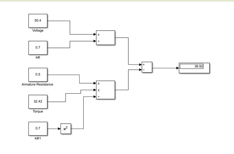
We calculate the value of 'T' from the previous solution which we obtain as 32.42 Nm and on putting that value into the equation we get the currect value of the speed.
We have used some constant blocks to assign the variable values and then using the arithmetic operators and a display block we have made the calculation easily using the simulink and hence the model is created .
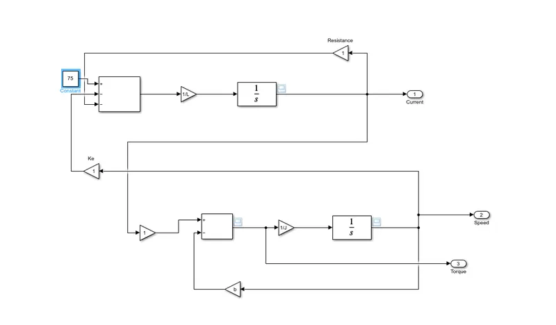
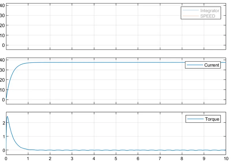
The output of the simulation gives us the following result
SOLUTION 4 :
Wally Rippel, in the given article can be seen discussing about the transformations in the HEVs and EVs since the 1960's. The evolution of the motors used in the EVs and HEVs. He looks deeply into the 2 major types of motors used in the EVs. They are Induction motors and DC Brushless motors .The differences , similarities , working principle and some other things are loooked into in this blog .
Initially he talks about the Brushless DC Motor , DC magnetic field will be gnerated by the permanent magnets present in the rotor of the motor. . This magnetic field enters the stator core and interacts with the current flowing through the windings, which produce a torque interaction between the rotor and stator. While the rotor rotates, the magnitude and polarity of the stator currents should be continuously varied , also the torque will remain constant and the conversion of electrical to mechanical energy is efficient. Inverter plays the role of controlling the current in BLDC Motor, Without it, brushless motors are of no use, emphasises the Tesla Engineer.
Then he explains about the Induction motor DRIVES.Induction motors have a rugged construction unlike the Brushless Motors . They have no magnets in it, just stacked laminations. The rotating magnetic field in this motor will be created by the current flowing through the stator windings . The frequency of the magnetic field from the rotor perspective will be the diffference between the applied frequency and rotor frequency . So there will be a speed difference between the rotor and frequency which will induce a voltage .Hence a current will be produced. This current when reacting with the original magnetic field , produces the torque . Inverter is not required in this model . Induction motors can be used to start under loaded condition too .
Then he discusses about the limitations of the induction motor, where he specified that they can be used only in AC and not with a DC supply. Also when run from utility power it acts like a constant speed machine too. Also the starting torque will also be limited, when compared to the DC competer.( even when an inverter is used to convert DC to AC for the inverter .)
There are many similarities in both the motors, like the stator and the type of inverters used. But the difference are with the type of rotor used and inverter controls . Also with the digital controllers, the only control differences will be the control code. Induction drives require only a speed sensor while the DC brushless drives require an absolute position sensor .
The BLDC Motors can be operated at unity power factor and also they have very less heating problems due to the efficient cooling system in the motor. But an induction motor can operate at a peak power factor of about 0.85 .
Whereas an induction motor when combined with a smart inverter can be more efficient than a BLDC Motor because both the magnetic and conduction losses varies in both . Permanent magnets are costly , so as the size of the motor grows the cost for BLDC Motor increases.
Induction motors are but difficult to control , due to the complex controlling techniques and formulas.
Finallly he adds that with reference to all the above factors , there is no perfect winner . Both the motors are good and it depends on the personal requirements . DC brushless drives will be used better in HEV mainly and can dominate in that segment of vehicles, and that induction drives will be mainly used for the high-performance pure electric vehicles .